EP0990188B1 - Bilddarstellungsvorrichtung für helmanzeige - Google Patents
Bilddarstellungsvorrichtung für helmanzeige Download PDFInfo
- Publication number
- EP0990188B1 EP0990188B1 EP98932242A EP98932242A EP0990188B1 EP 0990188 B1 EP0990188 B1 EP 0990188B1 EP 98932242 A EP98932242 A EP 98932242A EP 98932242 A EP98932242 A EP 98932242A EP 0990188 B1 EP0990188 B1 EP 0990188B1
- Authority
- EP
- European Patent Office
- Prior art keywords
- helmet
- display device
- visor
- light beam
- display system
- Prior art date
- Legal status (The legal status is an assumption and is not a legal conclusion. Google has not performed a legal analysis and makes no representation as to the accuracy of the status listed.)
- Revoked
Links
- 230000003287 optical effect Effects 0.000 claims description 26
- 230000000007 visual effect Effects 0.000 claims description 17
- 201000009310 astigmatism Diseases 0.000 claims description 8
- 239000011521 glass Substances 0.000 claims description 5
- 210000000887 face Anatomy 0.000 claims description 4
- 239000011248 coating agent Substances 0.000 claims 4
- 238000000576 coating method Methods 0.000 claims 4
- 238000012800 visualization Methods 0.000 description 7
- 230000004075 alteration Effects 0.000 description 5
- 230000005540 biological transmission Effects 0.000 description 4
- 238000012937 correction Methods 0.000 description 2
- 230000007547 defect Effects 0.000 description 2
- 239000011159 matrix material Substances 0.000 description 2
- 238000013459 approach Methods 0.000 description 1
- 230000000295 complement effect Effects 0.000 description 1
- 238000013461 design Methods 0.000 description 1
- 230000000694 effects Effects 0.000 description 1
- 238000004381 surface treatment Methods 0.000 description 1
- 238000012549 training Methods 0.000 description 1
- 238000013519 translation Methods 0.000 description 1
- 238000005303 weighing Methods 0.000 description 1
Images



Classifications
-
- B—PERFORMING OPERATIONS; TRANSPORTING
- B64—AIRCRAFT; AVIATION; COSMONAUTICS
- B64D—EQUIPMENT FOR FITTING IN OR TO AIRCRAFT; FLIGHT SUITS; PARACHUTES; ARRANGEMENT OR MOUNTING OF POWER PLANTS OR PROPULSION TRANSMISSIONS IN AIRCRAFT
- B64D10/00—Flight suits
-
- G—PHYSICS
- G02—OPTICS
- G02B—OPTICAL ELEMENTS, SYSTEMS OR APPARATUS
- G02B27/00—Optical systems or apparatus not provided for by any of the groups G02B1/00 - G02B26/00, G02B30/00
- G02B27/01—Head-up displays
- G02B27/017—Head mounted
- G02B27/0172—Head mounted characterised by optical features
-
- G—PHYSICS
- G02—OPTICS
- G02B—OPTICAL ELEMENTS, SYSTEMS OR APPARATUS
- G02B27/00—Optical systems or apparatus not provided for by any of the groups G02B1/00 - G02B26/00, G02B30/00
- G02B27/01—Head-up displays
- G02B27/0101—Head-up displays characterised by optical features
- G02B2027/011—Head-up displays characterised by optical features comprising device for correcting geometrical aberrations, distortion
Definitions
- the subject of the present invention is a device allowing the creation of light weight ergonomic helmet visuals, in which a bright image is observed superimposed on the vision of the exterior landscape.
- This type of helmet visual is used in the field aeronautics, the observer being the pilot of an airplane or a helicopter.
- weapons planes or combat helicopters require the presentation of piloting information, fire control information but also intensified shots concerning the environment of the plane or the helicopter. All this information can be presented on a head-up sight, present in all weapons planes and some helicopters.
- the first type concerns image distortion. Indeed, due to the strong variations of incidence on the visor, due to its inclination according to the field observed, the image projected on a visor is distorted (often called eccentric distortion of the second kind).
- the second type concerns the astigmatism introduced at the level of the image.
- the inclination of the visor has, for a given field, an influence on image quality within the same field: the radius of curvature seen in a given plane, differs from that observed in an orthogonal plane at first. The rays, with regard to these two planes, therefore focus on different places.
- Another solution is to introduce after the objective of taking view, an optical aberration correction device using a CCD circuit then a cathode ray tube to recreate a corrected image.
- an optical aberration correction device using a CCD circuit then a cathode ray tube to recreate a corrected image.
- Such device increases the weight of a pilot helmet and requires generally a high voltage supply, incompatible with a autonomous system capable of being taken on board with the pilot during ejection of the last.
- EP-A-077 193 discloses a helmet visual having a prism designed to compensate for distortion and astigmatism.
- the invention proposes a display device for helmet display using at least one prism optic comprising on one of its faces a selective treatment in angle of incidence and having optical aberrations capable of compensating for the distortion and astigmatism-type aberrations created by the visor at the level images.
- FIG. 1a relates to a matrix of image points not distorted.
- FIG. 1b relates to a matrix of deformed image points by the visor.
- the optical prism has an invariance by translation along a particular plane. Its refraction properties differ so within the same field between this plane and the plane which is its orthogonal, a phenomenon analogous to astigmatism.
- the subject of the invention is a device for display for helmet display according to claim 1.
- the device for visualization includes a single prism, operating in transmission, means for superimposing images and the outdoor scene being integrated into the visor.
- the helmet visual includes a visor 1 which has undergone a local surface treatment 01 of the type dielectric or holographic, to reflect a carrier light beam L1 intensified images, while allowing the transmission of a scene exterior.
- the light beam L1 is created from a device 2 comprising, according to another embodiment of the invention, a shooting objective 3 and a light intensifier 4.
- the light intensifier includes an input photocathode and a output cathode screen. The photons received on the shooting lens are transformed into electrons by the photocathode. The intensifier light accelerates and multiplies these electrons to finally form an image intensified on its CRT screen.
- This intensified image is sent in a relay view 5 made up in particular of a certain number of lenses 6 and return means 8 for directing the intensified image in visor direction.
- Relay optics also include the prism optic 7. The pilot's eye 11 thus observes the beam of intensified images L1 and the outdoor stage.
- the device visualization includes a prism operating in reflection.
- One of the major constraints of helmet visuals remains the heaviness of current devices. Any mass gain achieved in each of the elements of the helmet visual is important. Therefore, it can be particularly interesting, according to another embodiment of the invention, to double the passage of a light beam in the optical aberration correcting medium, in this case the prism optical. This double pass reduces the weight of the optical prism used, which represents an important advantage in the case of glass prisms of high optical index but also of high density.
- the display device of this mode illustrated in FIG. 4 is very similar to the device illustrated in FIG. 3. In this mode, the means of reference are integrated into the optical prism which functions in reflection.
- the helmet visual additionally includes an image generator for overlaying information on the images perceived by the pilot.
- This variant of the invention is illustrated in FIG. 5.
- the helmet visual includes an image generator 9 which can for example be a symbol generator generating a light beam L2. He understands also a mixing optic 10 receiving the images on the one hand intensified carried by the light beam L1 and on the other hand the images created by the image generator and carried by the light beam L2.
- an image generator 9 which can for example be a symbol generator generating a light beam L2.
- a mixing optic 10 receiving the images on the one hand intensified carried by the light beam L1 and on the other hand the images created by the image generator and carried by the light beam L2.
- the optical beams L1 and L2 can make more than one round trip in the optical prism. it can be particularly sought in the case of plastic optical prism, interesting in terms of weight, compared to glass but with a refractive index (close to 1.5) lower than that of the glasses used (close to 1.8) therefore introducing fewer optical corrections.
- the optical prism can have a reflective treatment on only part of one of its faces and also at least on part of another of its faces as illustrated in FIG. 6.
- the optical prism used in the invention can also include on one of its faces a selective angle of incidence treatment.
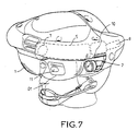
- FIG. 7 illustrates another embodiment of the invention which is a helmet equipped with the display device previously described in Figure 5.
- the helmet represents a version binocular to project information at both eyes of the pilot.
- the pilot's helmet includes two first side housings for shooting devices 2, two second lateral housings for image generators 9 which can be located above said first lateral housings as well as two mixers 10.
- the helmet also includes a set of two relay optics 5 and two prisms 7, output from which the generated images and intensified shots can be superimposed on the outdoor stage, in front of the pilot's eyes 11.
- FIG. 7 only the integrated left display device the helmet is shown, the same device not shown is integrated on the right side of the helmet.
- the means for superimpose an outdoor scene and the shots intensified include an independent glass combiner.
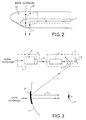
- the invention also applies in the case of a combiner not integrated into the visor which may have a curved surface of return as illustrated in Figure 2, this return surface creating the same type of distortion that a visor.
- This type of combiner includes a curved deflection surface Sc of center of curvature C, coupled to a prism complementary PC to direct the optical beam of intensified images or synthetic L in the direction of the pilot's eye 11.
- the optical prism may include means for passing through optical beams at least one round trip in said optical prism.
- the optical prism used in the device according to the invention can advantageously include, according to another embodiment, a curved face so as to approach the visor effect to better compensate for the optical aberrations introduced by the visor.
Landscapes
- Physics & Mathematics (AREA)
- General Physics & Mathematics (AREA)
- Optics & Photonics (AREA)
- Health & Medical Sciences (AREA)
- General Health & Medical Sciences (AREA)
- Pulmonology (AREA)
- Engineering & Computer Science (AREA)
- Aviation & Aerospace Engineering (AREA)
Claims (10)
- Anzeigevorrichtung für Helmanzeige, mit:wobei die Relaisoptik wenigstens ein optisches Prisma (7) umfaßt, das die Verzerrung und den Astigmatismus kompensiert, die durch die Sonnenblende in den Lichtstrahl (L1) eingeführt werden, dadurch gekennzeichnet, daß das Prisma auf einer seiner Flächen in bezug auf den Einfallswinkel selektiv bearbeitet ist.einer Bildverstärkervorrichtung, die ein Lichtstrahlenbündel (L1) liefern kann;einer Sonnenblende (1);Mitteln (01, 02), die eine äußere Szene und das von der Bildverstärkervorrichtung (2) über eine Relaisoptik (5) gelieferte Lichtstrahlenbündel (L1) vor einem Beobachter überlagern;
- Anzeigevorrichtung für Helmanzeige nach Anspruch 1, dadurch gekennzeichnet, daß sie einen Bildgenerator (9), der ein Informationen tragendes Lichtstrahlenbündel (L2) aussendet, und einen Mischer (10), der die Lichtstrahlenbündel (L1) und (L2) auf Höhe der Relaisoptik überlagert, umfaßt.
- Anzeigevorrichtung für Helmanzeige nach einem der Ansprüche 1 oder 2, dadurch gekennzeichnet, daß die Bildverstärkervorrichtung ein Bildaufnahmeobjektiv (3) und einen Lichtverstärker (4) umfaßt.
- Anzeigevorrichtung für Helmanzeige nach einem der Ansprüche 1 bis 3, dadurch gekennzeichnet, daß die Sonnenblende halbreflektierend bearbeitet ist, um eine äußere Szene und das Lichtstrahlenbündel (L1) oder die Lichtstrahlenbündel (L1) und (L2) vor einem Beobachter zu überlagern.
- Anzeigevorrichtung für Helmanzeige nach einem der Ansprüche 1 bis 3, dadurch gekennzeichnet, daß die Sonnenblende holographisch behandelt ist, um eine äußere Szene und das Lichtstrahlenbündel (L1) oder die Lichtstrahlenbündel (L1) und (L2) vor einem Beobachter zu überlagern.
- Anzeigevorrichtung für Helmanzeige nach einem der Ansprüche 1 bis 3, dadurch gekennzeichnet, daß sie einen Kombinierer aus Glas umfaßt, der eine äußere Szene und das Lichtstrahlenbündel (L1) oder die Lichtstrahlenbündel (L1) und (L2) vor einem Beobachter überlagert.
- Anzeigevorrichtung für Helmanzeige nach einem der Ansprüche 1 bis 6, dadurch gekennzeichnet, daß das optische Prisma Mittel umfaßt, damit das Strahlenbündel (L1) oder die Strahlenbündel (L1) und (L2) das optische Prisma wenigstens hin und zurück durchlaufen.
- Anzeigevorrichtung für Helmanzeige nach Anspruch 6, dadurch gekennzeichnet, daß das optische Prisma zwei Flächen umfaßt, die für das Lichtstrahlenbündel (L1) oder für die Lichtstrahlenbündel (L1) und (L2) wenigstens teilweise reflektierend sind.
- Anzeigevorrichtung für Helmanzeige nach einem der Ansprüche 1 bis 8, dadurch gekennzeichnet, daß das optische Prisma eine gekrümmte Fläche umfaßt, die die Kompensation der Verzerrung und des Astigmatismus, die durch die Sonnenblende in das Strahlenbündel (L1) oder in die Strahlenbündel (L1) und (L2) eingeführt werden, erhöht.
- Pilotenhelm, der eine Sonnenblende (1), zwei erste seitliche Aufnahmesitze für Bildverstärkervorrichtungen (2), die ein Lichtstrahlenbündel (L1) liefern, zwei zweite seitliche Aufnahmesitze für Bildgeneratoren (9), die ein Informationen tragendes Lichtstrahlenbündel (L2) aussenden, und zwei Mischer (10), die die Lichtstrahlenbündel (L1) und (L2) vor den Augen des Piloten über zwei Relaisoptiken überlagern, umfaßt, wobei die Relaisoptiken wenigstens zwei Prismen (7) umfassen, um die Verzerrung und den Astigmatismus, die durch die Sonnenblende eingeführt werden, zu kompensieren, wobei die Prismen auf einer ihrer Flächen in bezug auf den Einfallswinkel selektiv behandelt sind.
Applications Claiming Priority (3)
| Application Number | Priority Date | Filing Date | Title |
|---|---|---|---|
| FR9707711A FR2764997B1 (fr) | 1997-06-20 | 1997-06-20 | Dispositif de visualisation pour visuel de casque |
| FR9707711 | 1997-06-20 | ||
| PCT/FR1998/001294 WO1998059272A1 (fr) | 1997-06-20 | 1998-06-19 | Dispositif de visualisation pour visuel de casque |
Publications (2)
| Publication Number | Publication Date |
|---|---|
| EP0990188A1 EP0990188A1 (de) | 2000-04-05 |
| EP0990188B1 true EP0990188B1 (de) | 2002-08-28 |
Family
ID=9508236
Family Applications (1)
| Application Number | Title | Priority Date | Filing Date |
|---|---|---|---|
| EP98932242A Revoked EP0990188B1 (de) | 1997-06-20 | 1998-06-19 | Bilddarstellungsvorrichtung für helmanzeige |
Country Status (8)
| Country | Link |
|---|---|
| US (1) | US6304386B1 (de) |
| EP (1) | EP0990188B1 (de) |
| JP (1) | JP2002505017A (de) |
| AU (1) | AU8220898A (de) |
| DE (1) | DE69807478T2 (de) |
| FR (1) | FR2764997B1 (de) |
| WO (1) | WO1998059272A1 (de) |
| ZA (1) | ZA985357B (de) |
Families Citing this family (12)
| Publication number | Priority date | Publication date | Assignee | Title |
|---|---|---|---|---|
| US6379009B1 (en) * | 1996-04-24 | 2002-04-30 | James L. Fergason | Conjugate optics projection display with image enhancement |
| FR2792174B1 (fr) * | 1999-04-16 | 2001-09-21 | Sextant Avionique | Visiere pour casque |
| FR2793322B1 (fr) | 1999-05-07 | 2002-07-26 | Sextant Avionique | Dispositif optronique muni d'un miroir de mise au point pour projection sur visiere |
| EP1126298A1 (de) * | 2000-02-15 | 2001-08-22 | Leica Geosystems AG | Nachtsichtgerät |
| JP3733852B2 (ja) * | 2000-09-29 | 2006-01-11 | 日産自動車株式会社 | 表示装置 |
| DE102004012032A1 (de) * | 2004-03-11 | 2005-09-29 | Carl Zeiss Jena Gmbh | Anzeigevorrichtung und Anzeigeverfahren |
| JP4929725B2 (ja) * | 2006-01-19 | 2012-05-09 | 株式会社島津製作所 | ヘルメットマウントディスプレイ |
| US8376548B2 (en) | 2010-09-22 | 2013-02-19 | Vuzix Corporation | Near-eye display with on-axis symmetry |
| WO2014197109A2 (en) | 2013-03-22 | 2014-12-11 | Seiko Epson Corporation | Infrared video display eyewear |
| WO2017005614A1 (en) * | 2015-07-03 | 2017-01-12 | Essilor International (Compagnie Generale D'optique) | Methods and systems for augmented reality |
| TWI578022B (zh) * | 2015-10-23 | 2017-04-11 | 中強光電股份有限公司 | 頭戴式顯示裝置 |
| KR20190106879A (ko) * | 2019-05-08 | 2019-09-18 | 엘지전자 주식회사 | 전자 디바이스 |
Citations (3)
| Publication number | Priority date | Publication date | Assignee | Title |
|---|---|---|---|---|
| GB2261804A (en) * | 1991-04-22 | 1993-05-26 | Evans & Sutherland Computer Co | Head-mounted projection display system featuring beam splitter |
| EP0722106A2 (de) * | 1995-01-11 | 1996-07-17 | Canon Kabushiki Kaisha | Optisches System für Sucher |
| JPH08313829A (ja) * | 1995-05-18 | 1996-11-29 | Olympus Optical Co Ltd | 光学装置 |
Family Cites Families (12)
| Publication number | Priority date | Publication date | Assignee | Title |
|---|---|---|---|---|
| US3870405A (en) * | 1973-06-12 | 1975-03-11 | Honeywell Inc | Helmet sight visors |
| EP0066402B1 (de) * | 1981-05-29 | 1985-09-11 | Gec Avionics Limited | Nachtsichtvisier |
| DE3266408D1 (en) * | 1981-10-14 | 1985-10-24 | Gec Avionics | Optical arrangements for head-up displays and night vision goggles |
| GB8622378D0 (en) * | 1986-09-17 | 1987-01-14 | Gec Avionics | Helmet systems |
| US4761056A (en) * | 1987-03-27 | 1988-08-02 | Kaiser Aerospace And Electronics Corporation | Compact helmet mounted display |
| GB8825204D0 (en) * | 1988-10-27 | 1989-04-19 | Marconi Gec Ltd | Helmet systems |
| US4961626A (en) * | 1989-02-21 | 1990-10-09 | United Techologies Corporation | Direct incorporation of night vision in a helmet mounted display |
| GB9214909D0 (en) * | 1992-07-14 | 1992-08-26 | Secr Defence | Helmet-mounted optical systems |
| GB9217058D0 (en) * | 1992-08-12 | 1992-11-04 | Marconi Gec Ltd | Display system |
| EP0687932B1 (de) * | 1994-06-13 | 2005-05-25 | Canon Kabushiki Kaisha | Anzeigevorrichtung |
| JP3924348B2 (ja) * | 1996-11-05 | 2007-06-06 | オリンパス株式会社 | 画像表示装置 |
| US6195206B1 (en) * | 1998-01-13 | 2001-02-27 | Elbit Systems Ltd. | Optical system for day and night use |
-
1997
- 1997-06-20 FR FR9707711A patent/FR2764997B1/fr not_active Expired - Fee Related
-
1998
- 1998-06-19 DE DE69807478T patent/DE69807478T2/de not_active Revoked
- 1998-06-19 AU AU82208/98A patent/AU8220898A/en not_active Abandoned
- 1998-06-19 EP EP98932242A patent/EP0990188B1/de not_active Revoked
- 1998-06-19 ZA ZA985357A patent/ZA985357B/xx unknown
- 1998-06-19 US US09/446,363 patent/US6304386B1/en not_active Expired - Fee Related
- 1998-06-19 JP JP50389699A patent/JP2002505017A/ja active Pending
- 1998-06-19 WO PCT/FR1998/001294 patent/WO1998059272A1/fr not_active Ceased
Patent Citations (3)
| Publication number | Priority date | Publication date | Assignee | Title |
|---|---|---|---|---|
| GB2261804A (en) * | 1991-04-22 | 1993-05-26 | Evans & Sutherland Computer Co | Head-mounted projection display system featuring beam splitter |
| EP0722106A2 (de) * | 1995-01-11 | 1996-07-17 | Canon Kabushiki Kaisha | Optisches System für Sucher |
| JPH08313829A (ja) * | 1995-05-18 | 1996-11-29 | Olympus Optical Co Ltd | 光学装置 |
Also Published As
| Publication number | Publication date |
|---|---|
| AU8220898A (en) | 1999-01-04 |
| FR2764997A1 (fr) | 1998-12-24 |
| US6304386B1 (en) | 2001-10-16 |
| JP2002505017A (ja) | 2002-02-12 |
| EP0990188A1 (de) | 2000-04-05 |
| FR2764997B1 (fr) | 1999-09-03 |
| ZA985357B (en) | 1999-01-05 |
| DE69807478D1 (de) | 2002-10-02 |
| DE69807478T2 (de) | 2003-05-15 |
| WO1998059272A1 (fr) | 1998-12-30 |
Similar Documents
| Publication | Publication Date | Title |
|---|---|---|
| EP0365406B1 (de) | Optisches Kollimationssystem für eine Helmsichtanzeige | |
| EP0194196B1 (de) | Einspiegelungssichtgerät für Flugzeuge | |
| EP0475790B1 (de) | Optisches System zur Einspiegelung eines kollimierten Bildes ins Gesichtsfeld eines Beobachters für Nachtsichtanwendung und Helm mit mindestens einem derartigen System | |
| EP0834097B1 (de) | Mit anzeigesystem versehene kopfbedeckung | |
| EP0202987B1 (de) | Bildleitungs- und -kombinationsvorrichtung und ihre Anwendung in einem Helmsichtgerät | |
| EP2194418B1 (de) | Head-Up-Anzeige für Nachtsichtbrillen | |
| FR2638242A1 (fr) | Systeme optique de collimation, notamment pour visuel de casque | |
| EP0433145A1 (de) | Optische Einrichtung zur Darstellung von Sichtdaten im Unendlichen | |
| EP0990188B1 (de) | Bilddarstellungsvorrichtung für helmanzeige | |
| WO1991004508A2 (en) | Helmet mounted display | |
| FR2625336A1 (fr) | Systeme de visualisation tete haute et aeronef equipe d'un tel systeme | |
| FR2959022A1 (fr) | Dispositif de visualisation a "combineur" optique corrige des aberrations chromatiques | |
| US9470891B2 (en) | Head-up display for night vision goggles | |
| US8441734B2 (en) | Head-up display with optical combination providing protection against solar illumination | |
| EP1258771A1 (de) | Raumsparende optische Architektur für Helmvisier mit grossem Sichtfeld | |
| US11624905B2 (en) | Corrector plates for head mounted display system | |
| EP1057069B1 (de) | Optische vorrichtung mit rohrförmigen spiegel für am helm befestigtes sichtgerät | |
| EP1929356B1 (de) | Optische einrichtung zum überlagern von elektronischen bildern vor einer linse | |
| FR3115894A1 (fr) | Appareil de projection d’images et unité de pilotage associée | |
| EP0794448B1 (de) | Anzeigevorrichtung für Helmvisier | |
| US4361378A (en) | Biocular viewing apparatus | |
| EP0635743A1 (de) | Binokulares optisches Gerät mit erhöhter Auflösung und/oder vergrösserten Blichfeld, insbesondere für Nachtsicht (Gerät) | |
| FR3130954A1 (fr) | Viseur pour systeme de tir | |
| FR2644249A1 (fr) | Systeme optique de collimation, en particulier pour visuel de casque |
Legal Events
| Date | Code | Title | Description |
|---|---|---|---|
| PUAI | Public reference made under article 153(3) epc to a published international application that has entered the european phase |
Free format text: ORIGINAL CODE: 0009012 |
|
| 17P | Request for examination filed |
Effective date: 19991111 |
|
| AK | Designated contracting states |
Kind code of ref document: A1 Designated state(s): DE GB |
|
| 17Q | First examination report despatched |
Effective date: 20000728 |
|
| RAP1 | Party data changed (applicant data changed or rights of an application transferred) |
Owner name: THALES AVIONICS S.A. |
|
| GRAG | Despatch of communication of intention to grant |
Free format text: ORIGINAL CODE: EPIDOS AGRA |
|
| GRAG | Despatch of communication of intention to grant |
Free format text: ORIGINAL CODE: EPIDOS AGRA |
|
| GRAH | Despatch of communication of intention to grant a patent |
Free format text: ORIGINAL CODE: EPIDOS IGRA |
|
| GRAH | Despatch of communication of intention to grant a patent |
Free format text: ORIGINAL CODE: EPIDOS IGRA |
|
| GRAA | (expected) grant |
Free format text: ORIGINAL CODE: 0009210 |
|
| AK | Designated contracting states |
Kind code of ref document: B1 Designated state(s): DE GB |
|
| REG | Reference to a national code |
Ref country code: GB Ref legal event code: FG4D Free format text: NOT ENGLISH |
|
| REF | Corresponds to: |
Ref document number: 69807478 Country of ref document: DE Date of ref document: 20021002 |
|
| GBT | Gb: translation of ep patent filed (gb section 77(6)(a)/1977) |
Effective date: 20021202 |
|
| PLBQ | Unpublished change to opponent data |
Free format text: ORIGINAL CODE: EPIDOS OPPO |
|
| PLBI | Opposition filed |
Free format text: ORIGINAL CODE: 0009260 |
|
| PLAX | Notice of opposition and request to file observation + time limit sent |
Free format text: ORIGINAL CODE: EPIDOSNOBS2 |
|
| 26 | Opposition filed |
Opponent name: ELBIT SYSTEMS LTD. Effective date: 20030528 |
|
| PLAX | Notice of opposition and request to file observation + time limit sent |
Free format text: ORIGINAL CODE: EPIDOSNOBS2 |
|
| PLBB | Reply of patent proprietor to notice(s) of opposition received |
Free format text: ORIGINAL CODE: EPIDOSNOBS3 |
|
| RDAF | Communication despatched that patent is revoked |
Free format text: ORIGINAL CODE: EPIDOSNREV1 |
|
| RDAG | Patent revoked |
Free format text: ORIGINAL CODE: 0009271 |
|
| RDAC | Information related to revocation of patent modified |
Free format text: ORIGINAL CODE: 0009299REVO |
|
| 27W | Patent revoked |
Effective date: 20090121 |
|
| GBPR | Gb: patent revoked under art. 102 of the ep convention designating the uk as contracting state |
Effective date: 20090121 |
|
| R27W | Patent revoked (corrected) |
Effective date: 20090613 |
|
| PGFP | Annual fee paid to national office [announced via postgrant information from national office to epo] |
Ref country code: GB Payment date: 20090617 Year of fee payment: 12 Ref country code: DE Payment date: 20090615 Year of fee payment: 12 |
|
| RDAC | Information related to revocation of patent modified |
Free format text: ORIGINAL CODE: 0009299REVO |
|
| STAA | Information on the status of an ep patent application or granted ep patent |
Free format text: STATUS: PATENT REVOKED |
|
| R27W | Patent revoked (corrected) |
Effective date: 20090613 |