EP0194444A2 - Zahnprofil für Schraubenrotor - Google Patents
Zahnprofil für Schraubenrotor Download PDFInfo
- Publication number
- EP0194444A2 EP0194444A2 EP86101538A EP86101538A EP0194444A2 EP 0194444 A2 EP0194444 A2 EP 0194444A2 EP 86101538 A EP86101538 A EP 86101538A EP 86101538 A EP86101538 A EP 86101538A EP 0194444 A2 EP0194444 A2 EP 0194444A2
- Authority
- EP
- European Patent Office
- Prior art keywords
- tooth
- tooth profile
- point
- minimum pressure
- pressure angle
- Prior art date
- Legal status (The legal status is an assumption and is not a legal conclusion. Google has not performed a legal analysis and makes no representation as to the accuracy of the status listed.)
- Granted
Links
Images



Classifications
-
- F—MECHANICAL ENGINEERING; LIGHTING; HEATING; WEAPONS; BLASTING
- F01—MACHINES OR ENGINES IN GENERAL; ENGINE PLANTS IN GENERAL; STEAM ENGINES
- F01C—ROTARY-PISTON OR OSCILLATING-PISTON MACHINES OR ENGINES
- F01C1/00—Rotary-piston machines or engines
- F01C1/08—Rotary-piston machines or engines of intermeshing engagement type, i.e. with engagement of co- operating members similar to that of toothed gearing
- F01C1/082—Details specially related to intermeshing engagement type machines or engines
- F01C1/084—Toothed wheels
-
- Y—GENERAL TAGGING OF NEW TECHNOLOGICAL DEVELOPMENTS; GENERAL TAGGING OF CROSS-SECTIONAL TECHNOLOGIES SPANNING OVER SEVERAL SECTIONS OF THE IPC; TECHNICAL SUBJECTS COVERED BY FORMER USPC CROSS-REFERENCE ART COLLECTIONS [XRACs] AND DIGESTS
- Y10—TECHNICAL SUBJECTS COVERED BY FORMER USPC
- Y10T—TECHNICAL SUBJECTS COVERED BY FORMER US CLASSIFICATION
- Y10T74/00—Machine element or mechanism
- Y10T74/19—Gearing
- Y10T74/19642—Directly cooperating gears
- Y10T74/19698—Spiral
- Y10T74/19823—Screw
Definitions
- the present invention relates to a screw rotor tooth profile comprising a pair of male and female rotor tooth profiles engagedly rotatable around a couple of parallel shafts, said tooth profiles having leading and trailing flanks.
- Such screw rotor tooth profiles having a relatively large diameter are utilizable in hydraulic systems such as screw compressors, expanding machines or the like.
- a pair of rotor tooth profiles consisting of the theoretical tooth profiles fail to provide smooth rotational movements because they tend to be subjected to influences of machining and/or assembling errors in the tooth profiles, thermal expansion during their operation, etc.
- the above-mentioned modified type of rotor tooth profiles are disadvantageous in that it becomes difficult to keep proper tooth engagement on the leading flanks of the male and female rotor tooth profiles in case of occurrence of machining errors or errors of distance between the shafts on assembling in the rotor tooth profiles.
- the best force transmitting tooth surface (engaging tooth surface) on the leading flank is found at or close to the point of minimum pressure angle.
- the bottom part of the tooth of the female rotor is come into contact with the top part of the tooth of the male rotor.
- the present invention aims to provide screw rotor tooth profiles which are almost not susceptible to machining and/or assembling errors etc. of the rotor tooth profiles, that is, having an insensitivity to manufacturinq precision and which assure an optimum tooth engagement even in case that various errors noted above should occur in the machininq and/or assembling etc.
- a screw rotor tooth profile as mentioned in the first section wherein at least one of the male and female rotor tooth profiles has a point of minimum pressure angle or an enqaqinq tooth surface concurrinq with those of a theoretical tooth profile and is deviated from the theoretical tooth profile thereof such that the amount of deviation increases as going from the point of minimum pressure angle or the engaging tooth surface toward the tooth top side .and the tooth bottom side.
- said point of minimum pressure angle is determined on the leading flank of the theoretical tooth profile of the female tooth profile and the amount of the deviation increases as going from said point of minimum pressure angle toward a tooth top side and a tooth bottom side.
- the trailing flank connected to said leading flank is deviated from the theoretical tooth profile thereof such that the amount of the deviation is constant with respect to the direction of the normal line of said trailing flank.
- said leading flank of the female rotor tooth profile comprises a first leading flank which is formed by a hyperbola extending through a point deviated from the lowest tooth bottom point of said theoretical tooth profile in the direction of the normal line and said point of minimum pressure angle and a second leading flank which is formed by an arc of a circle with its radius center positioned inside a pitch circle of the female rotor tooth profile.
- said point of minimum pressure angle is determined on the trailing flank of the theoretical tooth profile of the female rotor tooth profile and the amount of the deviation increases as going from said point of minimum pressure angle toward a tooth top side and a tooth bottom side.
- said engaging tooth surface determined on the theoretical tooth profile is a point of minimum pressure angle.
- the single cutter is used for tooth cutting because the manufacture of hob for tooth cutting tool is difficult, but such cutting cannot cause precise cutting.
- the modified rotor tooth profiles according to the present invention make it possible to provide excellent tooth engagement required for force transmission even in case of the errors of cutting being large. Accordingly, the modified tooth profiles are very effective when applied to a large-sized screw compressor adopting large diameter rotor tooth profiles. Besides, said effect of the invention can also be provided by using the afore-described modified type of rotor tooth profiles in job cutting operations or the like where there is a possibility of occurrence of large errors.
- screw rotor tooth profiles at least one of the female and male rotor tooth profiles constructed as a pair of theoretical tooth profiles engaging each other with no clearance provided therebetween has a point of minimum pressure angle or an engaging tooth surface selected on the theoretical tooth profile to thereby obtain tooth engagement required for force transmission only at or close to said point of minimum pressure angle or an engaging tooth surface position, so that a pair of screw rotor tooth profiles can be provided which can hardly be influenced by machining and/or assembling errors, etc., that is, which have an insensitivity to manufacturing precision thereof.
- FIG. 1 there is shown one embodiment of a pair of screw rotor tooth profiles according to the present invention.
- solid lines show theoretical tooth profiles comprising a female rotor tooth profile 1 and a male rotor tooth profile 2 which engage each other with no clearance provided therebetween and rotate around respective shafts arranged in parallel.
- the theoretical tooth profile will be set forth before the invention screw rotor tooth profiles are explained.
- Figs. 1 and 2 the female rotor tooth profile 1 and a male rotor tooth profile 2 are shown on a plane perpendicular to rotating axes of rotors.
- the female rotor is driven by means of the male rotor.
- the rotor tooth profiles 1 and 2 are arranged to rotate respectively around center points 3 and 4 within a casing (not shown) so as to function as a compressor.
- the female rotor tooth profile 1 comprises, as its main parts, a leading flank 5 composed of a first leading flank 7 and second leading flank 8 and a trailing flank 6 composed of a first trailing flank 9 and second trailing flank 10. These main parts are located inside a pitch circle 11.
- the male rotor tooth profile 2 comprises, as its main parts, a leading flank 12 composed of a first leading flank 14 and second leading flank 15 and a trailing flank 13 composed of a first trailing flank 17 and second trailing flank 16. These main parts are located outside a pitch circle 18.
- the first leading flank 7 of the female rotor tooth profile 1 is formed between points 19 and 20.
- the second leading flank 8 defined between the points 20 and 22 is formed by an arc of a circle having radius R 2 with its center located at a point 23 inside the pitch circle 11 and the first trailing flank 9, defined between the points 19 and 24, is created by an arc of a circle having radius R S of the first trailing flank 17 of the male rotor 2.
- the second leading flank 10, defined between points 24 and 25, is formed by an arc of a circle having radius R 3 with its center located at a point 26 inside the pitch circle 11.
- first leading flank 14 defined between points 27 and 28 is created by the parabola of the first leading flank (between the points 19 and 20) of the female rotor tooth profile 1.
- second leading flank 15 defined between the points 28 and 29, and the second trailing flank 16, defined between points 30 and 31, are created respectively by the arc of the circle with the radius R 2 of said second leading flank 8 (between the points 20 and 22) of the female rotor tooth profile 1 and by the arc of the circle with the radius R 3 of said second trailing flank 10 (between the points 24 and 25) of the female rotor tooth profile 1.
- the form of the first trailing flank 17 between the points 27 and 30 is provided by an arc of a circle having radius R 5 with its center located at a point 32 on a line connecting the rotary shaft center points 3 and 4 of the female and male rotor tooth profiles 1 and 2.
- the first leading flank 5 of the female rotor tooth profile 1 has its point of minimum pressure angle (approximately 30°) disposed at a point 20 connecting the first leading flank 7 to the second leading flank 8, while the first leading flank 12 of the male rotor tooth profile 2 has its point of minimum pressure angle disposed at a point 28 connecting the first leading flank 14 to the second leading flank 15.
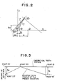
- the invention is achieved. For instance, when a deviation is given to the female rotor tooth profile alone, the point of minimum pressure angle 20 on the first leading flank 5 of the female rotor tooth profile 1, as shown in Figs. 1 through 3, is located on the theoretical tooth profile indicated by the solid line and, as preceeding from the point 20 toward the top side and bottom side of the tooth, the deviation is continuously increased as illustrated by a dotted line. That is, the deviation from the theoretical profile is given in a direction causing tooth thickness to diminish.
- the modified form of the female rotor tooth profile 1 is defined as follows.
- Reference numeral 8' indicates the second leading flank deviated from the second leading flank 8 of the theoretical tooth profile shown by the solid line.
- the second leading flank 8' is defined between the points 20 and 22' and formed by an arc of a circle having radius R 2 ' with its center located at a point 23' on a line connecting the point of minimum pressure angle 20 and the center 23 of the radius R 2 .
- the tip point 22' of the tooth indicates a point of intersection of an arc of the radius R 2 ' with an extension of a line connecting the rotation center 3 of the female tooth profile 1 to the center point 23' of the circular arc.
- the amount of deviation between the radii R 2 and R 2 is ⁇ 2 (0.1 - 0.15 mm) and the radius R 2 ' equals to the value R 2 - ⁇ 2 .
- the first leading flank 7' deviated from the first leading flank 7 of the theoretical tooth profile is formed by a hyperbola extending through a point 19' inwardly deviated by 6, (0.1 - 0.15 mm) from the lowest tooth bottom of the theoretical tooth profile and the point of minimum pressure angle 20.
- the amount of the deviation continuously increases as the deviation proceeds from the point 20 toward the point 19' of the tooth bottom.
- the reason for using the hyperbola on the first leading flank of the modified tooth profile instead of the parabola forming that of the theoretical tooth profile resides in the fact that the normal line at the point 20 of the first leading flank 7 of the theoretical tooth profile can be the same as the normal line at the point 20 of the deviated first leading flank 7': that is, thus both the first leading flanks can have a common normal line.
- the amount of the deviation from the theoretical tooth profile can continuously increase as the deviation proceeds from the point of minimum pressure angle 20 toward the tooth top and the tooth bottom thereof.
- the trailing flank 6 connected to the leading flank 5 is formed by a first trailing flank 9' and a second trailing flank 10' which are deviated in the normal line direction by a constant amount identical that of the deviation ⁇ 1 of the first leading flank 7'. More particularly, the first trailing flank 9' between the points 19' and 24' is deviated from the first trailing flank 9 of the theoretical tooth profile, shown by the solid line, by the amount ⁇ 1 in the tooth thickness decreasing direction. And, the second trailing flank 10' between the points 24' and 25' is formed by an arc of a circle with radius R 3 ' having its center located at a point 26. Here, it is determined that the value of the radius R 3 ' equals to R 3 - S 1 .
- said amounts of the deviation d 1 and ⁇ 2 may be identical or different.
- the hyperbola forming the first leading flank 7' is obtained as follows.
- constituent dimensions for the hyperbola are obtained from the x and y coordinate values at the point 20 and the value of ⁇ .
- Fig. 4 is a section taken along a plane perpendicular to the shafts showing another embodiment of the invention in which a deviation is provided at the leading flank of a male rotor with reference to a minimum pressure angle of the male rotor.
- parts with reference numerals and letters identical to those in Fig. 1 correspond to the counterparts in the embodiment already explained. Description for them, therefore, will be omitted.
- a point of minimum pressure angle 28 is located on the theoretical tooth profile shown by a solid line.
- Reference numeral 14 1 indicates a first leading flank deviated from the first leading flank 14 of the theoretical tooth profile shown by the solid line to the tooth thickness decreasing direction. The amount of this deviation on the first leading flank 14' continuously increases from the point 28 of minimum pressure angle.
- numeral 15' indicates a second leading flank deviated from the second leading flank 15 of the theoretical tooth profile shown by the solid line to the tooth thickness decreasing direction. The amount of deviation on said second leading flank-15' continuously increases from the point 28 of minimum pressure angle, and further a first and second trailing flanks 17' and 16' are given a constant amount of deviation.
- Fig. 5 is a section taken along a plane perpendicular to the shafts showing another embodiment in which a deviation is provided at the trailing flank of the female rotor with reference to a minimum pressure angle of the feamale rotor. This is corresponding to a case where the female rotor drives the male rotor.
- Numeral 9' indicates a first trailing flank deviated from the first trailing flank 9 of the theoretical tooth profile to the same direction as those already mentioned in the previous drawings and the amount of deviation on the first leading flank 9' also continuously increases from the point of minimum pressure angle 24.
- numeral 10' indicates a second trailing flank deviated from the second trailing flank 10 and the amount of deviation on the second following flank 10' also continuously increases from the point 24 of minimum pressure anqle.
Landscapes
- Engineering & Computer Science (AREA)
- Mechanical Engineering (AREA)
- General Engineering & Computer Science (AREA)
- Rotary Pumps (AREA)
- Applications Or Details Of Rotary Compressors (AREA)
Applications Claiming Priority (2)
| Application Number | Priority Date | Filing Date | Title |
|---|---|---|---|
| JP41091/85 | 1985-03-04 | ||
| JP60041091A JPS61201894A (ja) | 1985-03-04 | 1985-03-04 | スクリユ−ロ−タ歯形 |
Publications (3)
| Publication Number | Publication Date |
|---|---|
| EP0194444A2 true EP0194444A2 (de) | 1986-09-17 |
| EP0194444A3 EP0194444A3 (en) | 1987-12-16 |
| EP0194444B1 EP0194444B1 (de) | 1990-05-02 |
Family
ID=12598803
Family Applications (1)
| Application Number | Title | Priority Date | Filing Date |
|---|---|---|---|
| EP86101538A Expired - Lifetime EP0194444B1 (de) | 1985-03-04 | 1986-02-06 | Zahnprofil für Schraubenrotor |
Country Status (4)
| Country | Link |
|---|---|
| US (1) | US4671751A (de) |
| EP (1) | EP0194444B1 (de) |
| JP (1) | JPS61201894A (de) |
| DE (1) | DE3670879D1 (de) |
Cited By (2)
| Publication number | Priority date | Publication date | Assignee | Title |
|---|---|---|---|---|
| EP0591979A1 (de) * | 1992-10-09 | 1994-04-13 | Mayekawa Mfg Co.Ltd. | Zahnprofil für Schraubenrotor |
| EP1008755A1 (de) * | 1998-12-10 | 2000-06-14 | Carrier Corporation | Schraubenrotormaschine |
Families Citing this family (5)
| Publication number | Priority date | Publication date | Assignee | Title |
|---|---|---|---|---|
| JPS6463688A (en) * | 1987-09-01 | 1989-03-09 | Kobe Steel Ltd | Screw rotor for screw compressor |
| JPH0292087U (de) * | 1989-01-10 | 1990-07-20 | ||
| US5454701A (en) * | 1994-06-02 | 1995-10-03 | Chen; Chia-Hsing | Screw compressor with rotors having hyper profile |
| KR100425414B1 (ko) * | 2002-01-25 | 2004-04-08 | 이 재 영 | 스크류 압축기용 로우터의 치형 |
| JP4570497B2 (ja) * | 2005-03-25 | 2010-10-27 | 北越工業株式会社 | スクリュロータ及びスクリュロータの歯形補正方法 |
Family Cites Families (12)
| Publication number | Priority date | Publication date | Assignee | Title |
|---|---|---|---|---|
| US1813875A (en) * | 1931-03-19 | 1931-07-07 | Gear Proc Inc | Gear |
| CH244095A (de) * | 1943-03-25 | 1946-08-31 | Ebauchesfabrik Eta Ag | Verzahnung für Zeitmesser und Zählapparate. |
| SE312394B (de) * | 1965-05-10 | 1969-07-14 | A Lysholm | |
| US4140445A (en) * | 1974-03-06 | 1979-02-20 | Svenka Rotor Haskiner Aktiebolag | Screw-rotor machine with straight flank sections |
| GB1503488A (en) * | 1974-03-06 | 1978-03-08 | Svenska Rotor Maskiner Ab | Meshing screw rotor fluid maching |
| DD122841A1 (de) * | 1975-11-07 | 1976-11-05 | ||
| JPS5339508A (en) * | 1976-09-22 | 1978-04-11 | Hitachi Ltd | Screw rotor |
| JPS5793602A (en) * | 1980-12-03 | 1982-06-10 | Hitachi Ltd | Screw rotor |
| US4492546A (en) * | 1981-03-27 | 1985-01-08 | Hitachi, Ltd. | Rotor tooth form for a screw rotor machine |
| JPS5937291A (ja) * | 1982-08-27 | 1984-02-29 | Hitachi Ltd | スクリュー形流体機械のロータ歯形の製作方法 |
| US4475878A (en) * | 1982-09-27 | 1984-10-09 | Hitachi, Ltd. | Screw rotor with tooth form produced by thermal deformation and gear backlash |
| DE3278039D1 (en) * | 1982-10-25 | 1988-03-03 | Hitachi Ltd | Screw rotor machine |
-
1985
- 1985-03-04 JP JP60041091A patent/JPS61201894A/ja active Pending
-
1986
- 1986-02-06 EP EP86101538A patent/EP0194444B1/de not_active Expired - Lifetime
- 1986-02-06 DE DE8686101538T patent/DE3670879D1/de not_active Expired - Lifetime
- 1986-02-10 US US06/827,625 patent/US4671751A/en not_active Expired - Lifetime
Cited By (2)
| Publication number | Priority date | Publication date | Assignee | Title |
|---|---|---|---|---|
| EP0591979A1 (de) * | 1992-10-09 | 1994-04-13 | Mayekawa Mfg Co.Ltd. | Zahnprofil für Schraubenrotor |
| EP1008755A1 (de) * | 1998-12-10 | 2000-06-14 | Carrier Corporation | Schraubenrotormaschine |
Also Published As
| Publication number | Publication date |
|---|---|
| DE3670879D1 (de) | 1990-06-07 |
| US4671751A (en) | 1987-06-09 |
| EP0194444B1 (de) | 1990-05-02 |
| JPS61201894A (ja) | 1986-09-06 |
| EP0194444A3 (en) | 1987-12-16 |
Similar Documents
| Publication | Publication Date | Title |
|---|---|---|
| US5664655A (en) | Spline | |
| US3787154A (en) | Rotor profiles for helical screw rotor machines | |
| EP0174081B1 (de) | Schraubenrotorkompressor oder -expansionsmaschine | |
| EP0158514B1 (de) | Schraubenrotoren | |
| KR950008804B1 (ko) | 축과 허브를 연결하기 위한 치형시스템 | |
| CA1187461A (en) | Screw rotor machine and rotor profile therefor | |
| GB2296751A (en) | Planetary gear apparatus having epitrochoid teeth with a modified profile | |
| US4401420A (en) | Male and female screw rotor assembly with specific tooth flanks | |
| EP0194444B1 (de) | Zahnprofil für Schraubenrotor | |
| KR850005560A (ko) | 헤리컬 로우터 타입의 양변위(positive-displacement) 회전장치 및 그 장치용의 로우터 | |
| US4938672A (en) | Screw rotor lobe profile for simplified screw rotor machine capacity control | |
| US5066205A (en) | Screw rotor lobe profile for simplified screw rotor machine capacity control | |
| EP0053342B1 (de) | Schraubenrotor | |
| US10557523B2 (en) | Planetary gear train of internal engagement type | |
| JPS5993223A (ja) | 一体的な中心構造体をもつスパイラルベベルギヤの正面フライス生成方法とその方法により生成されたスパイラルベベルギヤ | |
| JP2005517139A (ja) | 潤滑剤用溝を備えた伝動装置 | |
| EP0961009B1 (de) | Gepaartes Schraubenrotorprofil | |
| US4678415A (en) | Rotary type fluid machine | |
| EP0591979B1 (de) | Zahnprofil für Schraubenrotor | |
| EP0087239B1 (de) | Kronrillen und Definition von deren Grundradius | |
| EP0211514A1 (de) | Schraubenrotorengefüge aufweisende Rotationsmaschine | |
| JPS6343597B2 (de) | ||
| JPH06101665A (ja) | スクロール流体機械 | |
| US4671750A (en) | Screw rotor mechanism with specific tooth profile | |
| JPH01208587A (ja) | スクリユーロータ |
Legal Events
| Date | Code | Title | Description |
|---|---|---|---|
| PUAI | Public reference made under article 153(3) epc to a published international application that has entered the european phase |
Free format text: ORIGINAL CODE: 0009012 |
|
| 17P | Request for examination filed |
Effective date: 19860206 |
|
| AK | Designated contracting states |
Kind code of ref document: A2 Designated state(s): DE FR GB IT NL SE |
|
| PUAL | Search report despatched |
Free format text: ORIGINAL CODE: 0009013 |
|
| RHK1 | Main classification (correction) |
Ipc: F01C 1/08 |
|
| AK | Designated contracting states |
Kind code of ref document: A3 Designated state(s): DE FR GB IT NL SE |
|
| 17Q | First examination report despatched |
Effective date: 19890215 |
|
| RBV | Designated contracting states (corrected) |
Designated state(s): DE SE |
|
| GRAA | (expected) grant |
Free format text: ORIGINAL CODE: 0009210 |
|
| AK | Designated contracting states |
Kind code of ref document: B1 Designated state(s): DE SE |
|
| REF | Corresponds to: |
Ref document number: 3670879 Country of ref document: DE Date of ref document: 19900607 |
|
| PLBE | No opposition filed within time limit |
Free format text: ORIGINAL CODE: 0009261 |
|
| STAA | Information on the status of an ep patent application or granted ep patent |
Free format text: STATUS: NO OPPOSITION FILED WITHIN TIME LIMIT |
|
| 26N | No opposition filed | ||
| EAL | Se: european patent in force in sweden |
Ref document number: 86101538.6 |
|
| PGFP | Annual fee paid to national office [announced via postgrant information from national office to epo] |
Ref country code: SE Payment date: 20041222 Year of fee payment: 20 |
|
| PGFP | Annual fee paid to national office [announced via postgrant information from national office to epo] |
Ref country code: DE Payment date: 20050304 Year of fee payment: 20 |
|
| EUG | Se: european patent has lapsed |