EP0194461B1 - Dispositif déchargeur pour machine à relier par adhésif - Google Patents
Dispositif déchargeur pour machine à relier par adhésif Download PDFInfo
- Publication number
- EP0194461B1 EP0194461B1 EP86101823A EP86101823A EP0194461B1 EP 0194461 B1 EP0194461 B1 EP 0194461B1 EP 86101823 A EP86101823 A EP 86101823A EP 86101823 A EP86101823 A EP 86101823A EP 0194461 B1 EP0194461 B1 EP 0194461B1
- Authority
- EP
- European Patent Office
- Prior art keywords
- delivery unit
- unit according
- conveyor
- adhesive
- carrying plates
- Prior art date
- Legal status (The legal status is an assumption and is not a legal conclusion. Google has not performed a legal analysis and makes no representation as to the accuracy of the status listed.)
- Expired
Links
- 239000000853 adhesive Substances 0.000 title claims description 8
- 230000001070 adhesive effect Effects 0.000 title claims description 8
- 238000000034 method Methods 0.000 title claims 2
- 239000000463 material Substances 0.000 claims description 2
- 239000011248 coating agent Substances 0.000 claims 1
- 238000000576 coating method Methods 0.000 claims 1
- 239000002184 metal Substances 0.000 claims 1
- 230000006835 compression Effects 0.000 description 2
- 238000007906 compression Methods 0.000 description 2
- 238000011161 development Methods 0.000 description 2
- 230000018109 developmental process Effects 0.000 description 2
- 239000003292 glue Substances 0.000 description 2
- 230000007704 transition Effects 0.000 description 2
- 238000006073 displacement reaction Methods 0.000 description 1
- 230000000694 effects Effects 0.000 description 1
- 238000009434 installation Methods 0.000 description 1
- 238000007665 sagging Methods 0.000 description 1
Images
Classifications
-
- B—PERFORMING OPERATIONS; TRANSPORTING
- B42—BOOKBINDING; ALBUMS; FILES; SPECIAL PRINTED MATTER
- B42C—BOOKBINDING
- B42C19/00—Multi-step processes for making books
- B42C19/08—Conveying between operating stations in machines
Definitions
- the invention relates to an execution device for perfect binding machines with a conveyor which delivers the book blocks emitted by the transport tongs of a perfect binding machine or the like in a straight line downward, on which the book blocks are laterally supported by guide plates with their backs, the conveyor having an obliquely downward direction Route section and a horizontal route section adjoining this.
- an adhesive binding machine in which an execution device is used with a horizontal conveyor arranged under a clamp chain conveyor, on which the book blocks are supported with their backs.
- the horizontal conveyor merges into a sloping section of the route and has lateral guide plates for erecting and guiding the flat cover on the book blocks.
- the finished books standing upright between the guide plates then reach a stacking shaft which adjoins the sloping section of the route.
- the products may also roll over at high transport speeds, so that the number of cycles of such products must be reduced from the outset.
- the object of the invention is to provide an execution device of the generic type which, while maintaining the short overall length, ensures gentle treatment of the products with a high cycle rate.
- the book blocks or the like arrive at the support plates with a minimum amount of fall height and are continuously and obliquely guided downwards out of the perfect binding machine and then transported into the horizontal plane, thereby ensuring the best possible protection of the products.
- the book blocks reach the support surface of a downstream machine without the interposition of another means of transport. Simultaneously with the leading out of the book blocks from the perfect binding machine, with the help of the execution device according to the invention, pressing of the areas close to the back, a so-called folding pressing on the block, can be carried out.
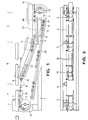
- the execution device for perfect binding machines has a conveyor with an endless roller chain 2, which is mounted around deflection sprockets 3, 4, 5 and 6, in a machine frame 7, is guided and driven in rotation with the transport tongs 8 of an adhesive binding machine.
- On the chain 2 are arranged at equal mutual distances, one-sided support plates 10 with a rear edge stop 10a.
- the support plates each consist of three individual interlocking and articulated interconnected plate members 11, 12 and 13, which are supported against one another in such a way that there is no sag in the direction of loading and thus a straight support surface for the book blocks 1 to be taken over by the transport tongs 8 of the perfect binding machine during the Export is maintained.
- the support plates 10 consisting of individual plate members, these only require a relatively small deflection radius, so that a trouble-free transfer of the book blocks to a subordinate edition 14 of a following machine is ensured without the use of additional transfer aids.
- the rear plate member 13 was given a shorter overall length in relation to the minimum book block height.
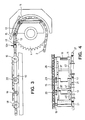
- the middle plate member 12 carries a laterally attached bar 15, see FIG. 4, with the adjacent plate members 11 and 13 overlapping and supported on them.
- the front plate member 11 is rotatable with its front side on an axle 16 mounted on the roller chain 2, while the rear plate member 13 on its rear side can be freely displaced in the longitudinal direction via a slide guide 17 on the roller chain 2 mounted axis 18 engages, which enables a length compensation in the deflections.
- the individual plate members 11, 12 and 13 interlock and are articulated to one another via axes 19, 20.
- the support plates 10 are supported with their rollers 21 on their return on a track 25 assigned to the lower chain center.
- control rollers 29 are located on the side adjacent to the roller chain on the axles 19 and 20, which roll-in ends 31 and 32 of the execution device follow the end radii following the deflection radii.
- the roller chain 2 with the articulated support plates 10 runs horizontally at a short distance from the transport tongs 8 and to them in a defined section A before they then lead into an obliquely downward direction Section B merges, which is ultimately followed by a horizontal section C.
- the inventive design of the support plates 10 prevents sagging of the plate members 11, 12, 13 in the loaded state, with the result that the book blocks 1 delivered to the support plates by the transport tongs 8 of the perfect binding machine with constant support of their backs on the support plates and under contact at the rear edge stop 10a, in the smallest space and with the greatest possible protection down out of the perfect binding machine. to then be brought into the horizontal plane for feeding into a slave machine.
- the book block 1 is held in its vertical position via guide plates 36 installed to the side of the movement path.
- These guide plates 36 can be configured on the inlet side as known erection elements, which are wound around 90, in order to erect the cover of books in the case of book blocks with envelopes glued to the back in the sense of closing the books as they are guided out of the perfect binding machine and to place them on the book block.
- the bar 15 which supports the plate member 12 forms a fixed stop with another bar 38 placed on the plate member 11, to which pressure bars 40, 41 and 42 are assigned on the opposite side, relative to the counter-holding bars 15 and 38 via control means (not shown) are movable in such a way that the pressure bars for receiving a book block can be moved back and then drive inwards against the book blocks for installation.
- a significantly increased pressure can also be exerted on the area of the book blocks near the back with regard to a folding pressure.
Landscapes
- Feeding Of Articles By Means Other Than Belts Or Rollers (AREA)
- Basic Packing Technique (AREA)
- Chain Conveyers (AREA)
- Delivering By Means Of Belts And Rollers (AREA)
Claims (10)
Applications Claiming Priority (2)
| Application Number | Priority Date | Filing Date | Title |
|---|---|---|---|
| DE3508236 | 1985-03-08 | ||
| DE19853508236 DE3508236A1 (de) | 1985-03-08 | 1985-03-08 | Ausfuhreinrichtung fuer klebebindemaschinen |
Publications (3)
| Publication Number | Publication Date |
|---|---|
| EP0194461A2 EP0194461A2 (fr) | 1986-09-17 |
| EP0194461A3 EP0194461A3 (en) | 1987-06-10 |
| EP0194461B1 true EP0194461B1 (fr) | 1989-07-12 |
Family
ID=6264571
Family Applications (1)
| Application Number | Title | Priority Date | Filing Date |
|---|---|---|---|
| EP86101823A Expired EP0194461B1 (fr) | 1985-03-08 | 1986-02-13 | Dispositif déchargeur pour machine à relier par adhésif |
Country Status (4)
| Country | Link |
|---|---|
| US (1) | US4681500A (fr) |
| EP (1) | EP0194461B1 (fr) |
| JP (1) | JPH0761801B2 (fr) |
| DE (2) | DE3508236A1 (fr) |
Families Citing this family (12)
| Publication number | Priority date | Publication date | Assignee | Title |
|---|---|---|---|---|
| JPH081105Y2 (ja) * | 1988-07-19 | 1996-01-17 | 凸版印刷株式会社 | 製本紙葉貼込機 |
| DE3930719A1 (de) * | 1989-09-14 | 1991-03-28 | Peter Lazar | Bindegeraet |
| DE4127207A1 (de) * | 1991-08-19 | 1993-02-25 | Kolbus Gmbh & Co Kg | Vorrichtung zum ueberfuehren von buechern o. dgl. produkte aus einer stehenden position in eine liegende position |
| JP3002926B2 (ja) * | 1992-05-18 | 2000-01-24 | ホリゾン・インターナショナル株式会社 | 製本機用本身供給装置 |
| JP3046976B2 (ja) * | 1992-05-27 | 2000-05-29 | ホリゾン・インターナショナル株式会社 | 製本機用排出装置 |
| FI93529C (sv) * | 1993-06-09 | 1995-04-25 | Gma Printing Syst Ab Oy | Matningsvändanordning för åtminstone delvis vikta tidningar eller tidskrifter |
| EP2422992B1 (fr) * | 2010-08-23 | 2018-09-19 | Müller Martini Holding AG | Procédé et dispositif destinés à la suspension d'un bloc de livre dans une couverture |
| DE102011018510A1 (de) * | 2011-04-23 | 2012-10-25 | Kolbus Gmbh & Co. Kg | Vorrichtung zum Zuführen von Buchblocks zu einer Buchbindemaschine |
| DE102011018509A1 (de) * | 2011-04-23 | 2012-10-25 | Kolbus Gmbh & Co. Kg | Vorrichtung zum Zuführen von Buchblocks zu einer Buchbindemaschine |
| GB2509695A (en) | 2012-11-09 | 2014-07-16 | Mcdonald George W | Apparatus for manufacture of an article |
| CN104944121B (zh) * | 2015-05-26 | 2020-04-07 | 上海浦东冷冻干燥设备有限公司 | 一种冻干机生产线的西林瓶脱框装置 |
| CN106113977B (zh) * | 2016-08-29 | 2018-03-20 | 大连天泰紫光装订设备有限公司 | 一种胶订机 |
Family Cites Families (6)
| Publication number | Priority date | Publication date | Assignee | Title |
|---|---|---|---|---|
| GB108880A (en) * | 1916-07-26 | 1917-08-30 | American Assembling Machine Co | Book or Pamphlet Covering Machine. |
| US1704454A (en) * | 1927-05-27 | 1929-03-05 | Donnelley & Sons Co | Straight-line bookbinding machine |
| JPS501909Y2 (fr) * | 1971-03-15 | 1975-01-18 | ||
| DE2226458A1 (de) * | 1972-05-26 | 1973-12-13 | Smith Mfg Co | Vorrichtung zum zufuehren von buechern zu einer bucheinbindemaschine |
| DD111331A1 (fr) * | 1973-07-02 | 1975-02-12 | ||
| JPS51107584A (en) * | 1975-03-17 | 1976-09-24 | Myano Tekkosho Kk | Kikaikakoniokeru kirikoshorisochi |
-
1985
- 1985-03-08 DE DE19853508236 patent/DE3508236A1/de not_active Withdrawn
-
1986
- 1986-02-13 DE DE8686101823T patent/DE3664292D1/de not_active Expired
- 1986-02-13 EP EP86101823A patent/EP0194461B1/fr not_active Expired
- 1986-03-07 JP JP61048758A patent/JPH0761801B2/ja not_active Expired - Fee Related
- 1986-03-07 US US06/837,704 patent/US4681500A/en not_active Expired - Lifetime
Non-Patent Citations (1)
| Title |
|---|
| "DEUTSCHER DRUCKER" Nr 28/9-9-1982 (Zeitschrift) Abb.19 * |
Also Published As
| Publication number | Publication date |
|---|---|
| US4681500A (en) | 1987-07-21 |
| DE3664292D1 (en) | 1989-08-17 |
| DE3508236A1 (de) | 1986-09-11 |
| EP0194461A2 (fr) | 1986-09-17 |
| EP0194461A3 (en) | 1987-06-10 |
| JPS61211210A (ja) | 1986-09-19 |
| JPH0761801B2 (ja) | 1995-07-05 |
Similar Documents
| Publication | Publication Date | Title |
|---|---|---|
| EP0623542B1 (fr) | Dispositif pour empiler un chant de feuilles imprimées | |
| CH692384A5 (de) | Verfahren und Anlage zum Herstellen eines Buches. | |
| EP0194461B1 (fr) | Dispositif déchargeur pour machine à relier par adhésif | |
| DE3344260A1 (de) | Vorrichtung zum zickzackfoermigen falten und stapeln von materialbahnen | |
| EP1001877B1 (fr) | Machine a coller les boites pliantes pour la production de boites pliantes a partir de decoupes | |
| DE3038058A1 (de) | Einrichtung zum aufstapeln von flachen gegenstaenden,insbesondere von faltschachtel-zuschnitten | |
| DE2164279C3 (de) | Vorrichtung zum automatischen Aufrichten von Kartonagenzuschnitten | |
| DE3817993C2 (de) | Einschlagvorrichtung für eine Maschine zum Herstellen von Bucheinbanddecken | |
| DE3024133A1 (de) | Foerder- und/oder stapelvorrichtung | |
| EP0872443A2 (fr) | Dispositif pour former une pile partielle s'étandant perpendiculèrement aux feuilles imprimées rangées sur la tranche et une à cÔté de l'autre | |
| DE10135659A1 (de) | Fördereinrichtung zur Förderung von Gegenständen, insbesondere von Druckprodukten | |
| DE3643026C2 (fr) | ||
| CH692943A5 (de) | Buch-Form- und -Pressmaschine. | |
| CH634530A5 (de) | Einrichtung zum foerdern und trennen von gefalteten druckprodukten. | |
| DE3733435A1 (de) | Verfahren zum formen, falzeinbrennen und ganzpressen von buechern und maschine zu seiner durchfuehrung | |
| DE2434360A1 (de) | Vorrichtung zum stapeln loser papierboegen | |
| EP0423481A1 (fr) | Dispositif pour déposer des sacs avec fond collé | |
| DE3212350A1 (de) | Vorrichtung zum auseinanderziehen von quer zur transportrichtung gegeneinander versetzten bogen von falzprodukten | |
| CH694525A5 (de) | Buchbindemaschine mit einer Transportvorrichtung zum kontinuierlichen Fördern von Blattstapeln in Taktabständen. | |
| DE3044557C2 (de) | Rundstapelbogenanleger | |
| DE2731838C2 (de) | Faltvorrichtung zum Zickzackfalten einer Endlosbahn | |
| EP0159622B1 (fr) | Machine de sérigraphie avec une table d'impression fixe | |
| DE2226446A1 (de) | Maschine zum Herstellen von Ein banddecken | |
| DE19725605A1 (de) | Verfahren und Vorrichtung zur Herstellung von mit Beilagen versehenen Falzexemplaren | |
| DE2521849C2 (de) | Rundstapelbogenanleger |
Legal Events
| Date | Code | Title | Description |
|---|---|---|---|
| PUAI | Public reference made under article 153(3) epc to a published international application that has entered the european phase |
Free format text: ORIGINAL CODE: 0009012 |
|
| AK | Designated contracting states |
Kind code of ref document: A2 Designated state(s): CH DE FR GB IT LI |
|
| PUAL | Search report despatched |
Free format text: ORIGINAL CODE: 0009013 |
|
| AK | Designated contracting states |
Kind code of ref document: A3 Designated state(s): CH DE FR GB IT LI |
|
| 17P | Request for examination filed |
Effective date: 19870625 |
|
| 17Q | First examination report despatched |
Effective date: 19881007 |
|
| GRAA | (expected) grant |
Free format text: ORIGINAL CODE: 0009210 |
|
| AK | Designated contracting states |
Kind code of ref document: B1 Designated state(s): CH DE FR GB IT LI |
|
| REF | Corresponds to: |
Ref document number: 3664292 Country of ref document: DE Date of ref document: 19890817 |
|
| ET | Fr: translation filed | ||
| GBT | Gb: translation of ep patent filed (gb section 77(6)(a)/1977) | ||
| ITF | It: translation for a ep patent filed | ||
| PLBE | No opposition filed within time limit |
Free format text: ORIGINAL CODE: 0009261 |
|
| STAA | Information on the status of an ep patent application or granted ep patent |
Free format text: STATUS: NO OPPOSITION FILED WITHIN TIME LIMIT |
|
| 26N | No opposition filed | ||
| ITTA | It: last paid annual fee | ||
| REG | Reference to a national code |
Ref country code: CH Ref legal event code: NV Representative=s name: A. BRAUN, BRAUN, HERITIER, ESCHMANN AG PATENTANWAE |
|
| PGFP | Annual fee paid to national office [announced via postgrant information from national office to epo] |
Ref country code: FR Payment date: 20001115 Year of fee payment: 16 |
|
| PGFP | Annual fee paid to national office [announced via postgrant information from national office to epo] |
Ref country code: GB Payment date: 20010207 Year of fee payment: 16 |
|
| REG | Reference to a national code |
Ref country code: GB Ref legal event code: IF02 |
|
| PG25 | Lapsed in a contracting state [announced via postgrant information from national office to epo] |
Ref country code: GB Free format text: LAPSE BECAUSE OF NON-PAYMENT OF DUE FEES Effective date: 20020213 |
|
| GBPC | Gb: european patent ceased through non-payment of renewal fee |
Effective date: 20020213 |
|
| PG25 | Lapsed in a contracting state [announced via postgrant information from national office to epo] |
Ref country code: FR Free format text: LAPSE BECAUSE OF NON-PAYMENT OF DUE FEES Effective date: 20021031 |
|
| REG | Reference to a national code |
Ref country code: FR Ref legal event code: ST |
|
| PGFP | Annual fee paid to national office [announced via postgrant information from national office to epo] |
Ref country code: DE Payment date: 20040204 Year of fee payment: 19 |
|
| PGFP | Annual fee paid to national office [announced via postgrant information from national office to epo] |
Ref country code: CH Payment date: 20040323 Year of fee payment: 19 |
|
| PG25 | Lapsed in a contracting state [announced via postgrant information from national office to epo] |
Ref country code: IT Free format text: LAPSE BECAUSE OF NON-PAYMENT OF DUE FEES;WARNING: LAPSES OF ITALIAN PATENTS WITH EFFECTIVE DATE BEFORE 2007 MAY HAVE OCCURRED AT ANY TIME BEFORE 2007. THE CORRECT EFFECTIVE DATE MAY BE DIFFERENT FROM THE ONE RECORDED. Effective date: 20050213 |
|
| PG25 | Lapsed in a contracting state [announced via postgrant information from national office to epo] |
Ref country code: LI Free format text: LAPSE BECAUSE OF NON-PAYMENT OF DUE FEES Effective date: 20050228 Ref country code: CH Free format text: LAPSE BECAUSE OF NON-PAYMENT OF DUE FEES Effective date: 20050228 |
|
| PG25 | Lapsed in a contracting state [announced via postgrant information from national office to epo] |
Ref country code: DE Free format text: LAPSE BECAUSE OF NON-PAYMENT OF DUE FEES Effective date: 20050901 |
|
| REG | Reference to a national code |
Ref country code: CH Ref legal event code: PL |