EP0194540A2 - Rotor et support de rotor d'un moteur électrique à entrefer sphérique - Google Patents
Rotor et support de rotor d'un moteur électrique à entrefer sphérique Download PDFInfo
- Publication number
- EP0194540A2 EP0194540A2 EP86102710A EP86102710A EP0194540A2 EP 0194540 A2 EP0194540 A2 EP 0194540A2 EP 86102710 A EP86102710 A EP 86102710A EP 86102710 A EP86102710 A EP 86102710A EP 0194540 A2 EP0194540 A2 EP 0194540A2
- Authority
- EP
- European Patent Office
- Prior art keywords
- rotor
- projection
- carrier
- sleeve
- bearing ball
- Prior art date
- Legal status (The legal status is an assumption and is not a legal conclusion. Google has not performed a legal analysis and makes no representation as to the accuracy of the status listed.)
- Withdrawn
Links
- 239000000463 material Substances 0.000 claims abstract description 7
- XEEYBQQBJWHFJM-UHFFFAOYSA-N Iron Chemical compound [Fe] XEEYBQQBJWHFJM-UHFFFAOYSA-N 0.000 description 2
- 241000209035 Ilex Species 0.000 description 1
- 238000013016 damping Methods 0.000 description 1
- 229910052742 iron Inorganic materials 0.000 description 1
- 238000007789 sealing Methods 0.000 description 1
- 229910000679 solder Inorganic materials 0.000 description 1
- 238000005476 soldering Methods 0.000 description 1
Images

Classifications
-
- F—MECHANICAL ENGINEERING; LIGHTING; HEATING; WEAPONS; BLASTING
- F16—ENGINEERING ELEMENTS AND UNITS; GENERAL MEASURES FOR PRODUCING AND MAINTAINING EFFECTIVE FUNCTIONING OF MACHINES OR INSTALLATIONS; THERMAL INSULATION IN GENERAL
- F16C—SHAFTS; FLEXIBLE SHAFTS; ELEMENTS OR CRANKSHAFT MECHANISMS; ROTARY BODIES OTHER THAN GEARING ELEMENTS; BEARINGS
- F16C17/00—Sliding-contact bearings for exclusively rotary movement
- F16C17/04—Sliding-contact bearings for exclusively rotary movement for axial load only
- F16C17/08—Sliding-contact bearings for exclusively rotary movement for axial load only for supporting the end face of a shaft or other member, e.g. footstep bearings
-
- H—ELECTRICITY
- H02—GENERATION; CONVERSION OR DISTRIBUTION OF ELECTRIC POWER
- H02K—DYNAMO-ELECTRIC MACHINES
- H02K5/00—Casings; Enclosures; Supports
- H02K5/04—Casings or enclosures characterised by the shape, form or construction thereof
- H02K5/16—Means for supporting bearings, e.g. insulating supports or means for fitting bearings in the bearing-shields
- H02K5/173—Means for supporting bearings, e.g. insulating supports or means for fitting bearings in the bearing-shields using bearings with rolling contact, e.g. ball bearings
Definitions
- the invention relates to the rotor and the rotor carrier of an electric motor with a spherical air gap between the rotor and a stator generating a rotating field, with a bearing ball carried by the rotor carrier in the center of the spherical air gap and a bearing pan rotating relative to the bearing ball and connected to the rotor.
- the rotor For electric motors with a spherical air gap, the rotor only needs a single, central bearing that is formed by a ball and socket.
- the rotor is supported against the rotor carrier via the bearing.
- the invention has for its object to reliably and with low wear to prevent the lifting of the rotor, to intercept and dampen precession movements of the rotor, to reduce noise development and not to impair the electrical and electromagnetic values of the electric motor.
- this object is achieved in that the rotor has an annular concentric projection in its interior, that the rotor carrier also has an annular concentric projection which is arranged in the space between the projection of the rotor and the bearing ball, and that the inner diameter of the projection of the rotor is smaller than the outer diameter of the projection connected to the rotor carrier.
- the two projections touch and not only prevent the rotor from lifting off, they also limit wobble or precession movements.
- At least one of the two overlapping projections consists of an elastically deformable material.
- the projection of the rotor is part of a concentric sleeve inserted into a concentric bore of the roto and the other projection is also part of a concentric sleeve connected to the rotor carrier, the bore in the concentric bore of the Rotor inserted sleeve is flared at its lower end.
- the sleeve having the projection of the rotor carrier has contact with the rotor carrier only at its lower end.
- the elastic deformability of the projection of this sleeve is thereby promoted, especially when not only the projection but the entire sleeve consists of an elastically deformable material.
- the rotor carrier has at its one end an edge which extends beyond the equator and surrounds the bearing ball.
- Such attachment of the bearing ball by a press fit on the rotor carrier is particularly advantageous because the highly polished and hardened ball cannot be contaminated by a solder.
- the advantageous fastening is a direct consequence of the arrangement of the projections according to the invention, because precession damping means no longer act on the bearing ball, as is the case in the prior art.
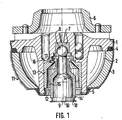
- the rotor 1 carries a magnetically active spherical cap 2 consisting of sintered iron.
- the spherical cap 2 is clamped to the base body of the rotor 1 with the addition of sealing rings 4 and 5 by means of a spherical shell-shaped hood 3 made of magnetically permeable material.
- a pump impeller 6 is riveted onto the base body of the rotor 1, because in this exemplary embodiment a structural unit of pump and motor is provided.
- the bearing ball 8 is fastened to a rotor carrier 10 arranged in the axis of rotation 9 by soldering.
- a spherical air gap 11 is formed between the rotor 1 and the stator, not shown here, of the electric motor, also not shown in detail.
- the bearing ball 8 is located in the center of the spherical air gap 11.
- a sleeve 13 is inserted, which is flared at its lower end 15. At the upper end, the sleeve 13 forms an annular concentric projection 16.
- the rotor arm 10 also carries a concentric sleeve 14, which has only at its lower part 14 1 contact with the rotor support 10 degrees.
- the sleeve 14 ends in an annular concentric projection 17, which is arranged in the space between the projection 16 of the rotor 1 and the bearing ball 8.
- the inside diameter of the projection 16 of the rotor 1 is smaller than the outside diameter of the projection 17 connected to the rotor carrier 10. In the normal position, which is shown in FIG. 1, there is a small distance between the two projections 16 and 17.
- the sleeve 14 with its projection 17 consists of an elastically deformable material.
- the sleeve 13 with its projection 16 consists of a non-elastically deformable material.
- the foot 18 of the rotor carrier 10 is connected to the electric motor, not shown here, so that the rotor carrier 10 is connected to the electric motor fixed to the housing.
Landscapes
- Engineering & Computer Science (AREA)
- General Engineering & Computer Science (AREA)
- Mechanical Engineering (AREA)
- Power Engineering (AREA)
- Motor Or Generator Frames (AREA)
- Linear Motors (AREA)
Applications Claiming Priority (2)
| Application Number | Priority Date | Filing Date | Title |
|---|---|---|---|
| DE19853508871 DE3508871A1 (de) | 1985-03-13 | 1985-03-13 | Rotor und rotortraeger eines elektromotors mit sphaerischem luftspalt |
| DE3508871 | 1985-03-13 |
Publications (2)
| Publication Number | Publication Date |
|---|---|
| EP0194540A2 true EP0194540A2 (fr) | 1986-09-17 |
| EP0194540A3 EP0194540A3 (fr) | 1987-06-03 |
Family
ID=6265003
Family Applications (1)
| Application Number | Title | Priority Date | Filing Date |
|---|---|---|---|
| EP86102710A Withdrawn EP0194540A3 (fr) | 1985-03-13 | 1986-03-01 | Rotor et support de rotor d'un moteur électrique à entrefer sphérique |
Country Status (3)
| Country | Link |
|---|---|
| EP (1) | EP0194540A3 (fr) |
| DE (1) | DE3508871A1 (fr) |
| DK (1) | DK111886A (fr) |
Cited By (2)
| Publication number | Priority date | Publication date | Assignee | Title |
|---|---|---|---|---|
| WO2009143580A1 (fr) * | 2008-05-30 | 2009-12-03 | Peter Biggs | Générateur d’énergie électrique |
| WO2019201989A1 (fr) * | 2018-04-17 | 2019-10-24 | Wobben Properties Gmbh | Générateur d'une éolienne et éolienne comprenant ce dernier |
Family Cites Families (4)
| Publication number | Priority date | Publication date | Assignee | Title |
|---|---|---|---|---|
| DE425935C (de) * | 1924-06-03 | 1926-03-01 | Xaver Bullinger | Lagerung von Wellen fuer Kleinmaschinen, insbesondere elektrischen Kleinstromerzeugern fuer Fahrraeder, Motorraeder u. dgl. |
| US2500978A (en) * | 1943-09-13 | 1950-03-21 | Oster John Mfg Co | Electric motor bearing |
| US3298756A (en) * | 1964-05-14 | 1967-01-17 | Rotron Mfg Co | Diaphragm thrust bearing |
| DE1538717A1 (de) * | 1966-09-07 | 1970-06-11 | Beteiligungs Ag Haustechnik | Elektrische Umlaufmaschine |
-
1985
- 1985-03-13 DE DE19853508871 patent/DE3508871A1/de not_active Withdrawn
-
1986
- 1986-03-01 EP EP86102710A patent/EP0194540A3/fr not_active Withdrawn
- 1986-03-11 DK DK111886A patent/DK111886A/da not_active Application Discontinuation
Cited By (2)
| Publication number | Priority date | Publication date | Assignee | Title |
|---|---|---|---|---|
| WO2009143580A1 (fr) * | 2008-05-30 | 2009-12-03 | Peter Biggs | Générateur d’énergie électrique |
| WO2019201989A1 (fr) * | 2018-04-17 | 2019-10-24 | Wobben Properties Gmbh | Générateur d'une éolienne et éolienne comprenant ce dernier |
Also Published As
| Publication number | Publication date |
|---|---|
| DK111886D0 (da) | 1986-03-11 |
| DK111886A (da) | 1986-09-14 |
| DE3508871A1 (de) | 1986-09-25 |
| EP0194540A3 (fr) | 1987-06-03 |
Similar Documents
| Publication | Publication Date | Title |
|---|---|---|
| DE3306322C2 (fr) | ||
| DE3884845T2 (de) | Kreiselpumpe für elektrische Haushaltsgeräte, wie Waschmaschinen, Geschirrspülmaschinen und ähnliches. | |
| DE19503521B4 (de) | Lüfter mit einem Lüfterrad | |
| DE3809277A1 (de) | Lageranordnung fuer axial kompakten kleinstventilator | |
| EP0962675A2 (fr) | Palier à roulement avec connexion électrique | |
| DE10156730B4 (de) | Berührungslose Dreherfassungsvorrichtung | |
| DE2417068B2 (de) | Schwenkvorrichtung fuer die welle eines uhrteiles | |
| DD272687A1 (de) | Elastisches distanzstueck fuer kugellager | |
| DE69204142T2 (de) | Winkelig vorgespanntes, selbsteinstellendes Lager. | |
| DE112017004388T5 (de) | Drehmaschine | |
| DE2625481A1 (de) | Lagervorrichtung fuer den anker eines elektromotors | |
| EP0194422A2 (fr) | Dispositif verrouillable pour une connexion | |
| EP0194540A2 (fr) | Rotor et support de rotor d'un moteur électrique à entrefer sphérique | |
| EP0612925B1 (fr) | Articulation à pivot | |
| EP0757188B1 (fr) | Etrier coulissant pour frein à disque avec support de prise de contact d'avertissement et câble d'avertissement | |
| DE1277519B (de) | Massageaufsteckgeraet, insbesondere fuer Trockenrasiergeraet | |
| DE69509455T2 (de) | Rotierende elektrische Maschine | |
| DD276605A3 (de) | Aufhaengung fuer eine wasserdichte waschtrommel | |
| DE10017807B4 (de) | Motor für eine Motor-Gebläseanordnung | |
| DE2533283A1 (de) | Anordnung zur lagerung von rotorwellen schnellaufender elektrokleinmotoren | |
| DE2045104C3 (de) | Einrichtung zur Übertragung einer Pendelbewegung auf einen Scheibenwischerarm | |
| DE19533991B4 (de) | Potentiometer | |
| DE3223057A1 (de) | Gehaeuseteil eines elektromotors mit einer loesbaren halteeinrichtung fuer ein lager | |
| DE4325305A1 (de) | Führung für den Schaft eines Offenend-Spinnrotors | |
| DE202011002247U1 (de) | Drehmagnet |
Legal Events
| Date | Code | Title | Description |
|---|---|---|---|
| PUAI | Public reference made under article 153(3) epc to a published international application that has entered the european phase |
Free format text: ORIGINAL CODE: 0009012 |
|
| 17P | Request for examination filed |
Effective date: 19860313 |
|
| AK | Designated contracting states |
Kind code of ref document: A2 Designated state(s): BE CH DE FR GB IT LI NL SE |
|
| PUAL | Search report despatched |
Free format text: ORIGINAL CODE: 0009013 |
|
| AK | Designated contracting states |
Kind code of ref document: A3 Designated state(s): BE CH DE FR GB IT LI NL SE |
|
| STAA | Information on the status of an ep patent application or granted ep patent |
Free format text: STATUS: THE APPLICATION HAS BEEN WITHDRAWN |
|
| 18W | Application withdrawn |
Withdrawal date: 19870707 |
|
| RIN1 | Information on inventor provided before grant (corrected) |
Inventor name: SCHMIDT, HANS-DIETER |