EP0194590B1 - Armature lumineuse allongée avec réflecteur incorporé - Google Patents
Armature lumineuse allongée avec réflecteur incorporé Download PDFInfo
- Publication number
- EP0194590B1 EP0194590B1 EP86102981A EP86102981A EP0194590B1 EP 0194590 B1 EP0194590 B1 EP 0194590B1 EP 86102981 A EP86102981 A EP 86102981A EP 86102981 A EP86102981 A EP 86102981A EP 0194590 B1 EP0194590 B1 EP 0194590B1
- Authority
- EP
- European Patent Office
- Prior art keywords
- mirror
- lamp
- light
- built
- deflecting mirror
- Prior art date
- Legal status (The legal status is an assumption and is not a legal conclusion. Google has not performed a legal analysis and makes no representation as to the accuracy of the status listed.)
- Expired - Lifetime
Links
- 238000005286 illumination Methods 0.000 claims description 3
- 230000003287 optical effect Effects 0.000 claims 2
- 238000009434 installation Methods 0.000 description 2
- 239000000725 suspension Substances 0.000 description 2
- 230000004907 flux Effects 0.000 description 1
- 230000004313 glare Effects 0.000 description 1
- 238000000034 method Methods 0.000 description 1
- 230000005855 radiation Effects 0.000 description 1
Images
Classifications
-
- F—MECHANICAL ENGINEERING; LIGHTING; HEATING; WEAPONS; BLASTING
- F21—LIGHTING
- F21V—FUNCTIONAL FEATURES OR DETAILS OF LIGHTING DEVICES OR SYSTEMS THEREOF; STRUCTURAL COMBINATIONS OF LIGHTING DEVICES WITH OTHER ARTICLES, NOT OTHERWISE PROVIDED FOR
- F21V17/00—Fastening of component parts of lighting devices, e.g. shades, globes, refractors, reflectors, filters, screens, grids or protective cages
- F21V17/02—Fastening of component parts of lighting devices, e.g. shades, globes, refractors, reflectors, filters, screens, grids or protective cages with provision for adjustment
-
- F—MECHANICAL ENGINEERING; LIGHTING; HEATING; WEAPONS; BLASTING
- F21—LIGHTING
- F21V—FUNCTIONAL FEATURES OR DETAILS OF LIGHTING DEVICES OR SYSTEMS THEREOF; STRUCTURAL COMBINATIONS OF LIGHTING DEVICES WITH OTHER ARTICLES, NOT OTHERWISE PROVIDED FOR
- F21V14/00—Controlling the distribution of the light emitted by adjustment of elements
- F21V14/04—Controlling the distribution of the light emitted by adjustment of elements by movement of reflectors
-
- F—MECHANICAL ENGINEERING; LIGHTING; HEATING; WEAPONS; BLASTING
- F21—LIGHTING
- F21V—FUNCTIONAL FEATURES OR DETAILS OF LIGHTING DEVICES OR SYSTEMS THEREOF; STRUCTURAL COMBINATIONS OF LIGHTING DEVICES WITH OTHER ARTICLES, NOT OTHERWISE PROVIDED FOR
- F21V7/00—Reflectors for light sources
- F21V7/04—Optical design
- F21V7/09—Optical design with a combination of different curvatures
-
- F—MECHANICAL ENGINEERING; LIGHTING; HEATING; WEAPONS; BLASTING
- F21—LIGHTING
- F21Y—INDEXING SCHEME ASSOCIATED WITH SUBCLASSES F21K, F21L, F21S and F21V, RELATING TO THE FORM OR THE KIND OF THE LIGHT SOURCES OR OF THE COLOUR OF THE LIGHT EMITTED
- F21Y2103/00—Elongate light sources, e.g. fluorescent tubes
Definitions
- the invention relates to an elongated luminaire with built-in mirror optics for a rod-shaped lamp according to the preamble of claim 1.
- Luminaires of this type are mostly referred to as wallwashers and have an extremely asymmetrical light distribution for uniform illumination of vertical surfaces such as walls, shelves and counters.
- the luminaires must be mounted at a certain distance from the vertical surface in order to achieve uniform illumination. This optimal installation distance is set at a ratio of 1: 3 to the suspension height or wall height. Due to structural conditions or subsequent changes, this requirement can practically often not be met and therefore no ideal lighting conditions are achieved.
- an electric lamp with a rod-shaped light source in which a partially movable reflector with variable light distribution is installed in a housing.
- the reflector is formed from a cylindrical part which is fixed to the housing and surrounds the lamp approximately semicircularly and a flat leg which is articulated thereon.
- the light is emitted either downwards or in an approximately horizontal direction. This does not result in an extremely obliquely radiating luminaire, but the light is emitted in the upper half-space.
- a luminaire is known from DE-A 33 16000 in which an elongated light source faces a channel-shaped reflector arrangement which is open at the bottom.
- This consists of a head mirror and two movable side mirrors, each of which can be adjusted around a swivel axis on the bottom edge of the housing. This allows the light emission to be changed from more narrow beam to more wide beam.
- the side mirrors touch the head mirror during the swiveling process and are held on it.
- the invention has for its object to improve a lamp of the type mentioned in such a way that the light intensity indicatrix of each individual lamp can be optimally adapted to different suspension heights and mounting distances without glare.
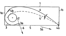
- the lamp shown schematically in cross section in the single figure has an elongated box-shaped housing 1, on the one long side 1 a of which a fluorescent lamp 2 is preferably arranged. This is surrounded by a semicircular secondary mirror 3, which is followed by an approximately parabolically curved deflecting mirror 4 above a light exit opening 5 of the lamp.
- the deflection mirror 4 is pivotally mounted on the longitudinal side 1b of the housing facing away from the lamp and, with its pivot axis 4a, also forms the boundary of the light exit opening on this side.
- the light exit opening is limited by a bend 3a of the secondary mirror. This also prevents a direct view of the fluorescent lamp from below to the level indicated by an arrow 6.
- the deflecting mirror 4 engages with its free edge 4b above the fluorescent lamp 2 under the secondary mirror 3. This ensures that no greater luminous flux losses occur when the deflecting mirror is pivoted into the position 4 'indicated in dashed lines.
- the pivoting range of the deflecting mirror which can be determined within this range by means not shown, comprises an angle ⁇ of approximately 15 °.
- the luminous intensity distribution body of the luminaire can thus be changed such that the light emerging from the light exit opening approximately in the direction of arrow 5a optimally fulfills the respective lighting task.
Landscapes
- Engineering & Computer Science (AREA)
- General Engineering & Computer Science (AREA)
- Non-Portable Lighting Devices Or Systems Thereof (AREA)
- Securing Globes, Refractors, Reflectors Or The Like (AREA)
Claims (2)
- Luminaire de forme allongée avec un système optique à miroirs incorporé destiné à une lampe (2) en forme de barre et présentant une distribution assymétrique de la lumière, de préférence du type à appliquer sur des surfaces planes horizontales pour illuminer des surfaces verticales, le système optique à miroirs étant constitué par un miroir capteur (3) fixe entourant la lampe (2) à peu près en demi-cercle, et par un miroir déflecteur (4) pivotant autour d'un axe (4a) s'étendant dans le sens de la longueur du luminaire, ledit luminaire étant caractérisé en ce que le miroir déflecteur (4) et le miroir capteur (3) sont configurés de manière à pouvoir se chevaucher avec un écartement variable au-dessus et à l'arrière de la lampe (2), et en ce que l'axe de pivotement (4a) du miroir déflecteur (4) est prévu sur le côté de boîtier (1b) opposé à la lampe (2) et constitue la limite de l'orifice de passage de lumière (5).
- Luminaire selon la revendication 1, caractérisé en ce que la plage de pivotement du miroir déflecteur (4) forme un angle (α) d'environ 15°.
Applications Claiming Priority (2)
| Application Number | Priority Date | Filing Date | Title |
|---|---|---|---|
| DE8507634U DE8507634U1 (de) | 1985-03-15 | 1985-03-15 | Langgestreckte Leuchte mit eingebauter Spiegeloptik |
| DE8507634U | 1985-03-15 |
Publications (3)
| Publication Number | Publication Date |
|---|---|
| EP0194590A2 EP0194590A2 (fr) | 1986-09-17 |
| EP0194590A3 EP0194590A3 (en) | 1988-07-06 |
| EP0194590B1 true EP0194590B1 (fr) | 1991-06-05 |
Family
ID=6778690
Family Applications (1)
| Application Number | Title | Priority Date | Filing Date |
|---|---|---|---|
| EP86102981A Expired - Lifetime EP0194590B1 (fr) | 1985-03-15 | 1986-03-06 | Armature lumineuse allongée avec réflecteur incorporé |
Country Status (2)
| Country | Link |
|---|---|
| EP (1) | EP0194590B1 (fr) |
| DE (2) | DE8507634U1 (fr) |
Families Citing this family (6)
| Publication number | Priority date | Publication date | Assignee | Title |
|---|---|---|---|---|
| DE3711366A1 (de) * | 1987-04-04 | 1988-10-27 | Pohlschroeder & Co Kg | Rasterleuchte fuer arbeitsplaetze |
| GB2214285B (en) * | 1988-01-20 | 1992-04-08 | Light Years Ahead Ltd | Space lighting |
| DE9004579U1 (de) * | 1990-04-23 | 1990-06-28 | Licentia Patent-Verwaltungs-Gmbh, 6000 Frankfurt | Asymmetrisch strahlende Leuchte |
| AT406506B (de) * | 1997-08-18 | 2000-06-26 | Bartenbach Christian | Leuchte |
| CA2346580C (fr) | 2000-05-08 | 2008-07-15 | Sylvan R. Shemitz Designs, Inc. | Luminaire a distribution asymetrique |
| DE20114380U1 (de) * | 2001-08-31 | 2002-02-21 | Dr. Hönle AG, 82152 Planegg | UV-Bestrahlungsvorrichtung |
Family Cites Families (2)
| Publication number | Priority date | Publication date | Assignee | Title |
|---|---|---|---|---|
| DE1497369A1 (de) * | 1966-10-25 | 1969-06-04 | Zumtobel Kg Elektrovertriebsge | Elektrische Leuchte fuer Krankenbetten |
| DE3316000A1 (de) * | 1983-05-03 | 1984-11-08 | Licentia Patent-Verwaltungs-Gmbh, 6000 Frankfurt | Leuchte fuer eine langgestreckte lichtquelle |
-
1985
- 1985-03-15 DE DE8507634U patent/DE8507634U1/de not_active Expired
-
1986
- 1986-03-06 DE DE8686102981T patent/DE3679575D1/de not_active Expired - Fee Related
- 1986-03-06 EP EP86102981A patent/EP0194590B1/fr not_active Expired - Lifetime
Also Published As
| Publication number | Publication date |
|---|---|
| EP0194590A3 (en) | 1988-07-06 |
| EP0194590A2 (fr) | 1986-09-17 |
| DE8507634U1 (de) | 1985-11-14 |
| DE3679575D1 (de) | 1991-07-11 |
Similar Documents
| Publication | Publication Date | Title |
|---|---|---|
| EP0898686B2 (fr) | Systeme d'eclairage muni d'un corps de base servant de support pour au moins une lampe | |
| DE19635906C2 (de) | Leuchte mit einer Reflektor- und Abschirmungsanordnung | |
| DE3412162C1 (de) | Langgestreckte Leuchte | |
| EP0194590B1 (fr) | Armature lumineuse allongée avec réflecteur incorporé | |
| EP0768492B1 (fr) | Appareil d'éclairage indirect à faisceau large | |
| DE3316000A1 (de) | Leuchte fuer eine langgestreckte lichtquelle | |
| EP0684425A2 (fr) | Luminaire avec au moins une source lumineuse | |
| EP0638764B1 (fr) | Lampadaire à éclairage principalement direct | |
| EP0952390A2 (fr) | Chemin lumineux | |
| EP3865761B1 (fr) | Luminaire à fonction combinée de luminaire insert et de spot | |
| DE3836611A1 (de) | Decken-einbauleuchte fuer eine paneeldecke | |
| DE10252724A1 (de) | Verlichtingstoestel | |
| DE3112253C2 (fr) | ||
| DE4111299C2 (de) | Breitstrahlende Leuchte mit Reflektoranordnung | |
| DE4143328A1 (de) | Arbeitsplatzleuchte | |
| DE2615107C3 (de) | Mittelstreifenleuchte für Richtungsfahrbahnen | |
| EP2813753B1 (fr) | Éclairage | |
| EP0678706B1 (fr) | Armature d'éclairage encastrée au plafond | |
| WO2001065170A1 (fr) | Pylone d'eclairage | |
| DE10213536B4 (de) | Sekundärbeleuchtungssystem sowie Leuchte mit einem solchen Sekundärbeleuchtungssystem | |
| DE1212461B (de) | Autobahnpfostenleuchte | |
| DE3310862C2 (de) | Breitstrahlende Reflektoranordnung für Leuchten mit räumlich ausgedehnter Lichtquelle | |
| DE10041367B4 (de) | Leuchte mit Parabelabschnitten | |
| EP1009950B1 (fr) | Systeme de reflecteur pour lampes d'eclairage exterieur | |
| DE650611C (de) | Beleuchtungskoerper mit Reflektor |
Legal Events
| Date | Code | Title | Description |
|---|---|---|---|
| PUAI | Public reference made under article 153(3) epc to a published international application that has entered the european phase |
Free format text: ORIGINAL CODE: 0009012 |
|
| AK | Designated contracting states |
Kind code of ref document: A2 Designated state(s): BE DE GB IT LU NL |
|
| PUAL | Search report despatched |
Free format text: ORIGINAL CODE: 0009013 |
|
| AK | Designated contracting states |
Kind code of ref document: A3 Designated state(s): BE DE GB IT LU NL |
|
| 17P | Request for examination filed |
Effective date: 19881222 |
|
| 17Q | First examination report despatched |
Effective date: 19900226 |
|
| GRAA | (expected) grant |
Free format text: ORIGINAL CODE: 0009210 |
|
| AK | Designated contracting states |
Kind code of ref document: B1 Designated state(s): BE DE GB IT LU NL |
|
| REF | Corresponds to: |
Ref document number: 3679575 Country of ref document: DE Date of ref document: 19910711 |
|
| GBT | Gb: translation of ep patent filed (gb section 77(6)(a)/1977) | ||
| ITF | It: translation for a ep patent filed | ||
| PG25 | Lapsed in a contracting state [announced via postgrant information from national office to epo] |
Ref country code: GB Effective date: 19920306 |
|
| PG25 | Lapsed in a contracting state [announced via postgrant information from national office to epo] |
Ref country code: LU Free format text: LAPSE BECAUSE OF NON-PAYMENT OF DUE FEES Effective date: 19920331 Ref country code: BE Effective date: 19920331 |
|
| PLBE | No opposition filed within time limit |
Free format text: ORIGINAL CODE: 0009261 |
|
| STAA | Information on the status of an ep patent application or granted ep patent |
Free format text: STATUS: NO OPPOSITION FILED WITHIN TIME LIMIT |
|
| 26N | No opposition filed | ||
| BERE | Be: lapsed |
Owner name: LICENTIA PATENT-VERWALTUNGS-G.M.B.H. Effective date: 19920331 |
|
| PG25 | Lapsed in a contracting state [announced via postgrant information from national office to epo] |
Ref country code: NL Effective date: 19921001 |
|
| GBPC | Gb: european patent ceased through non-payment of renewal fee | ||
| NLV4 | Nl: lapsed or anulled due to non-payment of the annual fee | ||
| PG25 | Lapsed in a contracting state [announced via postgrant information from national office to epo] |
Ref country code: DE Effective date: 19921201 |
|
| PG25 | Lapsed in a contracting state [announced via postgrant information from national office to epo] |
Ref country code: IT Free format text: LAPSE BECAUSE OF NON-PAYMENT OF DUE FEES;WARNING: LAPSES OF ITALIAN PATENTS WITH EFFECTIVE DATE BEFORE 2007 MAY HAVE OCCURRED AT ANY TIME BEFORE 2007. THE CORRECT EFFECTIVE DATE MAY BE DIFFERENT FROM THE ONE RECORDED. Effective date: 20050306 |