EP0194627A2 - Machine automatique de cerclage pourvue d'un appareil de tension et de scellage - Google Patents
Machine automatique de cerclage pourvue d'un appareil de tension et de scellage Download PDFInfo
- Publication number
- EP0194627A2 EP0194627A2 EP86103156A EP86103156A EP0194627A2 EP 0194627 A2 EP0194627 A2 EP 0194627A2 EP 86103156 A EP86103156 A EP 86103156A EP 86103156 A EP86103156 A EP 86103156A EP 0194627 A2 EP0194627 A2 EP 0194627A2
- Authority
- EP
- European Patent Office
- Prior art keywords
- strapping
- stamp
- tensioning
- holding
- electrode
- Prior art date
- Legal status (The legal status is an assumption and is not a legal conclusion. Google has not performed a legal analysis and makes no representation as to the accuracy of the status listed.)
- Granted
Links
- 238000007789 sealing Methods 0.000 title 1
- 238000003466 welding Methods 0.000 claims abstract description 27
- 229920003023 plastic Polymers 0.000 claims description 3
- 239000004033 plastic Substances 0.000 claims description 3
- 238000000034 method Methods 0.000 description 7
- 230000001960 triggered effect Effects 0.000 description 3
- 229910000831 Steel Inorganic materials 0.000 description 2
- 238000009413 insulation Methods 0.000 description 2
- 230000001404 mediated effect Effects 0.000 description 2
- 229920002635 polyurethane Polymers 0.000 description 2
- 239000010959 steel Substances 0.000 description 2
- 241000530268 Lycaena heteronea Species 0.000 description 1
- 230000000712 assembly Effects 0.000 description 1
- 238000000429 assembly Methods 0.000 description 1
- 239000004020 conductor Substances 0.000 description 1
- 238000001816 cooling Methods 0.000 description 1
- 239000000498 cooling water Substances 0.000 description 1
- 230000003628 erosive effect Effects 0.000 description 1
- 230000004048 modification Effects 0.000 description 1
- 238000012986 modification Methods 0.000 description 1
- 230000003287 optical effect Effects 0.000 description 1
- 239000006223 plastic coating Substances 0.000 description 1
- 239000004814 polyurethane Substances 0.000 description 1
- 238000003825 pressing Methods 0.000 description 1
Images


Classifications
-
- B—PERFORMING OPERATIONS; TRANSPORTING
- B65—CONVEYING; PACKING; STORING; HANDLING THIN OR FILAMENTARY MATERIAL
- B65B—MACHINES, APPARATUS OR DEVICES FOR, OR METHODS OF, PACKAGING ARTICLES OR MATERIALS; UNPACKING
- B65B13/00—Bundling articles
- B65B13/18—Details of, or auxiliary devices used in, bundling machines or bundling tools
- B65B13/24—Securing ends of binding material
- B65B13/32—Securing ends of binding material by welding, soldering, or heat-sealing; by applying adhesive
- B65B13/327—Hand tools
Definitions
- the invention relates to a strapping machine with a tensioning and closing device according to the preamble of claim 1.
- a strapping machine of the aforementioned type is known from DD-A 50 487 (business patent).
- the features of the preamble are realized in the known device.
- the adjustable plate which carries the counter electrode, is attached to a lever linkage, which is attached in a rigid arrangement to another lever and swings out of the effective range of the holding stamp in a circular arc movement after the welding process has ended.
- This device has the disadvantage that the protrudingly attached Plate must absorb significant forces and torques that require a correspondingly large dimensioning.
- the high stamping pressures required can lead to deformations and thus possibly poor welding results.
- the plate with the counter electrode can be moved into the area of the stamp elements in such a way that it is held on both sides without tilting.
- the strapping is reliably carried on one level and long service lives can be expected.
- the adjustable plate can be moved in and out, for example, via a lever and an attached bearing shoe in which the end of the adjustment lever rotates.
- the adjustment lever itself can be actuated hydraulically or mechanically, for example by the action of cams.
- the adjustable plate consists of two plate elements sliding on each other, namely an upper and a lower sliding plate, which have stops which are offset in the sliding direction, one of the sliding plates carrying the bearing shoe.
- the lower sliding plate is preferably run over by the upper sliding plate in such a way that a guide channel located in the upper sliding plate is positioned above the counter electrode.
- This guide channel serves to receive and precisely place the strapping band.
- a stop lever can also be seen at the end of the guide channel, which performs a rotary movement when touching or abutting the belt and triggers a shading process with this rotary movement
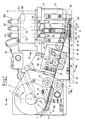
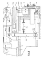
- FIG. 1 shows a side view of the functional side of a tensioning and closing device for an automatic strapping machine.
- a strapping 1 is around an object, for. B. a coil, a bale or the like, around.
- the course of the strapping tape 1 which runs next to or below the tensioning and closing device, is indicated by a dashed loop 2.
- the strapping tape is removed from a supply roll (not shown). The individual assemblies of the tensioning and closing device are explained below in accordance with the belt pass
- the tension disc 3 the thickness of which corresponds to the fire width, carries a clamping rocker 12 in the area of the band entry, which in turn carries the clamping strip 6 lying transversely to the strip periphery, the effective area of this clamping strip 6 being oriented tangentially to the circumference of the clamping disc 13, 14 each run on one side of the tensioning disk 3 and are pivoted at 1 5.
- a tension spring 16 pulls the clamping rocker 1 2 in the counterclockwise direction (in FIG. 1). If the tensioning disk 3 is in its waiting position, as shown in FIG. 1, the terminal strip 6 strikes against the front side of one Tape guide bar 17.
- the strap guide 17 carries the strapping 1 on its top.
- the straightener 31 has five straightening rollers 32, 33 offset from one another.
- the lower three straightening rollers 33 are mounted on the machine frame.
- the middle one, 33 ', is coupled to a drive 34.
- the upper straightening rollers 32 can be set in parallel by means of an adjusting screw 35. As a result, the alignment of the strapping can be adjusted precisely.
- the straightener 31 is divided in the feed channel 30, which continues in a discharge channel 36, and between the upper and lower straightening rollers and can be opened by means of a quick-release fastener, which consists of a lever 37 with a pressure spring 38.
- the strapping band 1 passes from the discharge channel 36 from the straightening unit 31 into a holding and welding station 40.
- the holding and welding station 40 is delimited by two lateral pylons 41 and 42 which are screwed onto the machine frame 4 and carry a closure plate 75, which is shown in FIG is omitted for drawing reasons, but is shown in Figure 6 a.
- a closure plate 75 which is shown in FIG is omitted for drawing reasons, but is shown in Figure 6 a.
- four stamp elements 44, 45, 46 and 47 are arranged next to one another in a column shape, each of which can be moved vertically.
- the first stamp element 44 is the first holding stamp, which is provided in its foot region with a feed channel 48 for the strapping band 1 to be guided loosely.
- the first holding stamp continues upwards into a bearing head 49, which receives a bearing fork 50 in a recess, which a slight evasive movement between the bearing fork 50 and the holding stamp 44 allows.
- the bearing fork 50 in turn is carried by the end of a piston rod 51 which is fastened to a piston which is movably arranged within a piston-cylinder arrangement 52 and can be controlled via a control valve 53.
- Two further piston-cylinder arrangements 54 and 55 are combined with the former (52) in a system block and are surrounded by a housing 64. They are controlled by associated control valves 54 'and 55'.
- the second and third stamp elements 46 and 46 are arranged. , net, which are both movable at the same time and are also carried by the same piston-cylinder arrangement 54.
- the stamp elements 45 and 46 are provided with a common support head 56 in which they are held.
- Disc springs 57 are arranged in the interior of the two stamp elements 45 and 46, which allow an electrode head 58 or 58 'to be pressed evenly even with slight erosion.
- Such spring elements are essential, since an exact adjustment is not possible by the hydraulics alone.
- a correspondingly large-volume cooling housing 59 which is provided with connections 60, 60 ′ for cooling water, belongs to the electrode head 58.
- the electrode head 58 is provided in a manner known per se with corresponding insulation devices, power supply lines and the like, which are not shown in detail.
- the stamp element 45 also comprises a shear knife 61 which is attached laterally above the electrode head 58 and slides on the side of the first stamp element 5 4 , so that the strapping band 1 coming from the feed channel 48 can be cut in the region of the first stamp element 44.
- the last stamp element 47 is another hat stamp.
- the cut ribbon end is pressed onto the end of the ribbon loop 2 already formed and held by means of a holding foot 63.
- This stamp element 47 can also be actuated by a corresponding piston-cylinder arrangement 55 with an associated valve 55 '.
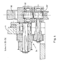
- FIG. 5 shows further details of the structure.
- the cylinders of the piston-cylinder arrangements 52, 54 and 55 required for the vertical movement of the stamp elements are contained in a housing 64.
- the cylinder rods protrude downward from the housing 64.
- a further, horizontally operating piston-cylinder arrangement 65 is attached to the machine frame 4 in an oscillating manner with the cylinder 66.
- a lever 68 is moved over the cylinder rod 62 and is suspended with one arm at its upper end - (68 ').
- the lever 68 ends at its lower end 69 in a shoe 70.
- the shoe 70 is connected to an upper sliding plate 71.
- the upper slide plate 7 1 slides out on a lower slide plate 72, in the front end of which a counter electrode 73 is embedded, which can also be designed as a short-circuit plate. When the electrodes are pressed on and the ends of the strip lie on top of each other, a circuit is closed that enables the welding process.
- In the extreme right position of the lower sliding plate 72 as shown in FIG.
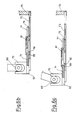
- a stop lever 78 is mounted in the upper sliding plate 72, which has a stop head 79 and a release foot 80 and is mounted at 81.
- the release foot 80 accordingly moves towards the viewer of FIG. 6 a when the stop head 79 moves away from the viewer
- Trigger head 80 triggers a switching pulse when approaching via a microswitch (not shown), which is also built into the upper sliding plate 71.
- the stop lever 78 is brought back into the starting position via a resetting spring element (not shown)
- FIGS. 6 b and 6 c show the different positions of the upper and lower sliding plates 71, 72 relative to one another.
- the tape 1 is threaded and the stop head 79 triggered.
- This switching pulse moves the lever 68 with the piston rod 62 to the left until the stop 82 abuts against the stop surface 83 of the lower door plate.
- This moves the upper plate 71 so far that the end 71 'releases the counter electrode 73.
- the strapping band now lies exactly above the counter electrode and below the electrode 58.
- the welding process is triggered by the electrode 58 moving downward and generating a current surge.
- the upper plate 71 then moves further to the left and takes now the lower slide plate 72, so that the welded tape loop is released.
- the strapping tape likewise arrives from the discharge channel 36 from the straightening unit 31 into a welding and welding station 140.
- the holding and welding station 140 is delimited by two lateral pylons 41 and 42 which are on the machine frame 4 are screwed on and carry a closure plate 43.
- This closure plate 43 has been partially broken away in FIG. 1 in order to be able to represent the parts lying under the closure plate.
- Behind the closure plate 43 four stamp elements 144, 145, 146 and 147 are arranged next to one another in a column shape, each of which can be moved vertically.
- the first stamping element 144 is the first holding stamp, which is provided in its foot region with a feed channel 4 8 for the strapping band 1 to be guided loosely.
- the first holding stamp continues upwards up to a plunger 144 ′, which is below one of a cam 150 area to be driven over ends
- the stamping element 144 like the stamping elements 145 to 147 described below, is provided with a plate spring.
- the second stamp element 145 which is provided with an electrode head 154, is arranged in a sliding manner next to the first stamp element 144.
- the electrode head 154 is provided in a manner known per se with corresponding insulation devices, current leads and the like.
- the stamp element 145 also comprises a shear knife 155, which is attached laterally above the electrode head 154 and slides on the side of the first stamp element 14 4 , so that the steel strip 1 coming from the feed channel 48 can be sheared or cut in its area.
- the stamp element 145 is followed by a further stamp element 146, which is also equipped with an electrode head. Both stamp elements 145 and 146 end in plungers 145 'and 145' below further cams 151, 152.
- the cams 151 and 152 are arranged such that the electrode heads slide down simultaneously and at the same depth.
- the last stamp element 147 is another holding stamp.
- the cut end of the band is pressed onto the end of the band loop 2 already formed by means of a holding foot 156 and can be held there.
- This stamp element 147 is also actuated by plungers 147 'and via a cam 153
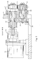
- the structure is shown in the sectional drawing according to FIG.
- a translationally movable slide 160 provided below with the cams 1 50 -153, which is designed as a laterally guided plate.
- a holding joint 1 61 is firmly attached, which is connected to the piston rod 162
- Piston-cylinder system 163 is connected The cylinder of this system 163 is in turn firmly connected at 164 to the machine frame 4. Accordingly, when the rod 162 is extended and retracted from the system 163, the slide 160 with the cams 150 to 153 moves horizontally back and forth. In this case, as shown in the functional description explained the die members 144 and 1 47 pressed upon reaching the cam downward.
- the slider 160 is provided with a stop roller 166, which presses against a lever 1 68 suspended at 167.
- the lever 168 is equipped as a one-armed lever and ends at its lower end 169 in a shoe 1 70.
- the shoe 170 is in turn connected via a rod 171 to a sliding short-circuit plate 172 which, also sliding horizontally, can be pulled out of its position below the two electrode heads 154.
- the short circuit plate 172 is made of a conductive material, e.g. B. copper, made in the support area against the rest of the machine frame and the rod 171, it is of course isolated.
- the plunger elements 144 to 147 can be pulled back into their upper position against the direction of movement, which is triggered by the cams 150 to 153, by four tension springs 174, 175, each associated with a plunger element, as soon as the cams have been pulled out of the plunger contact position again are. The same is true for the withdrawal of the short-circuit plate 172. These, too, is retrieved by retracting the slide by a spring 1 76 back into the closure position
- the holding and welding station with the stamp elements arranged directly next to one another is able to ensure clamping, cutting and welding on a relatively short piece of tape over a short distance and in the smallest space.
- the initially mentioned belt loop 2 which comes out of the holding and welding station 140 and circles the package, is introduced again through a guide channel 177 which is provided with a switch 178 which is to be actuated by the belt end. With the help of this switch, the speed of advance of the belt 1 is reduced.
- a limit switch 179 is also attached to the end of the holding and welding station, which is actuated when the band tip is coming in and switches off the advance of the band
- the strapping 1 To "thread” the strapping 1, it is inserted between the tensioning disk 3 and the clamping strip 6, which are at a sufficient distance, and is pushed into the contact area of the drive rollers 20, 21. After the drive rollers 20, 21 have been turned on, the belt is passed through the feed channel 30, the straightening unit 31 and the discharge channel 36. At this point, all stamp elements 1 4 4 to 147 have moved up; the slide 60 has moved so far in front of the end face of the machine frame 4 that the lever 1 68 is released, so that the contact plate 172 has moved into the position shown in dashed lines in FIG. 8 and closes the channel of the holding and welding station 140. The belt can now be released be pushed through this channel.
- the band 155 is cut off by the knife 155, so that there is a strapping loosened from the rest of the band supply. Then the two electrode heads 15 4 , 15 4 'press firmly on the overlapping area of the ribbon loop. The welding current is switched on. A high current intensity is formed via the short-circuit plate, which leads to two welding spots in the electrode head area. The current is switched off again and the slide 160 is retracted. Due to the spring force, electrodes detach from the belt loop and the two holding stamps 144 and 147 from the overlap area. The slider 160 moves back until it touches the lever 68 and thus pulls the short-circuiting plate back out of the electrode area. The tape loop can fall down. Due to the tensile stress built up in the belt loop, the belt loop is also released from the guide channel 177, which is provided with trap door-like closure plates which fold down. The package can be accepted with a fully automatic strapping.
- the device lifts off the package.
- the slider 160 moves back into the basic position, so that the short-circuit plate 172 can again move back to its original position.
- the tensioning disk moves back and thus releases the terminal block.
- the driver rollers start again and start a new strapping process.
- the device according to FIGS. 1, 5, 6 a to c differs in its function only in the area of the upper and lower sliding plates.
- hydraulic controls for the stamp elements are provided instead of the cam controls.
- the function is analogous to that described above and can already be seen from the descriptions of the figures.
- this may also be suitable for welding plastic strips
Landscapes
- Engineering & Computer Science (AREA)
- Mechanical Engineering (AREA)
- Basic Packing Technique (AREA)
Priority Applications (1)
| Application Number | Priority Date | Filing Date | Title |
|---|---|---|---|
| AT86103156T ATE58101T1 (de) | 1985-03-13 | 1986-03-08 | Umreifungsautomat mit spann- und verschlussvorrichtung. |
Applications Claiming Priority (4)
| Application Number | Priority Date | Filing Date | Title |
|---|---|---|---|
| DE3508837 | 1985-03-13 | ||
| DE19853508837 DE3508837A1 (de) | 1985-03-13 | 1985-03-13 | Spann- und verschlussvorrichtung fuer einen umreifungsautomaten |
| DE19853508835 DE3508835A1 (de) | 1985-03-13 | 1985-03-13 | Spannvorrichtung fuer einen umreifungsautomaten |
| DE3508835 | 1985-03-13 |
Publications (3)
| Publication Number | Publication Date |
|---|---|
| EP0194627A2 true EP0194627A2 (fr) | 1986-09-17 |
| EP0194627A3 EP0194627A3 (en) | 1987-11-25 |
| EP0194627B1 EP0194627B1 (fr) | 1990-11-07 |
Family
ID=25830248
Family Applications (1)
| Application Number | Title | Priority Date | Filing Date |
|---|---|---|---|
| EP86103156A Expired - Lifetime EP0194627B1 (fr) | 1985-03-13 | 1986-03-08 | Machine automatique de cerclage pourvue d'un appareil de tension et de scellage |
Country Status (4)
| Country | Link |
|---|---|
| US (1) | US4689938A (fr) |
| EP (1) | EP0194627B1 (fr) |
| CA (1) | CA1301046C (fr) |
| DE (1) | DE3675410D1 (fr) |
Cited By (2)
| Publication number | Priority date | Publication date | Assignee | Title |
|---|---|---|---|---|
| US5894789A (en) * | 1996-05-08 | 1999-04-20 | Orgapack Ag | Tensioning arrangement |
| WO2011042191A1 (fr) * | 2009-10-10 | 2011-04-14 | Sms Logistiksysteme Gmbh | Cercleuse automatique pour ligaturer des lots d'objets, notamment des bandes métalliques enroulées en paquets |
Families Citing this family (7)
| Publication number | Priority date | Publication date | Assignee | Title |
|---|---|---|---|---|
| DE102011017431A1 (de) | 2010-04-29 | 2011-12-01 | Sms Logistiksysteme Gmbh | Vorrichtung und Verfahren zum Umreifen von aufgewickelten Bunden, insbesondere von Stahlbunden |
| US9745090B2 (en) | 2012-04-24 | 2017-08-29 | Signode Industrial Group Llc | Modular strapping machine for steel strap |
| KR101701205B1 (ko) * | 2016-04-08 | 2017-03-02 | 주식회사 삼정제이피에스 | 코일 포장용 결속 헤드 모듈 |
| CN107697340A (zh) * | 2017-06-30 | 2018-02-16 | 深圳大工人科技有限公司 | Dgr‑iiia型超声波焊式全自动pet打捆机 |
| CN109502072B (zh) * | 2018-12-23 | 2024-05-17 | 洛阳曜辰自动化科技有限公司 | 一种基于手持式气动打包机的双机头全自动打包装置 |
| US11174051B2 (en) | 2019-02-15 | 2021-11-16 | Samuel, Son & Co. (Usa) Inc. | Hand held strapping tool |
| US12397943B2 (en) | 2022-11-29 | 2025-08-26 | Samuel, Son & Co. (Usa) Inc. | Handheld strapping device |
Family Cites Families (10)
| Publication number | Priority date | Publication date | Assignee | Title |
|---|---|---|---|---|
| DE1586203B1 (de) * | 1967-02-07 | 1971-08-12 | Nichiro Kogyo K K | Vorrichtung zur Fuehrung eines Bandes,insbesondere an der Verbindungsstelle von Bandanfang und Bandende bei einer Verschnuerungsmaschine |
| US3771436A (en) * | 1970-12-26 | 1973-11-13 | Ikegai Iron Works Ltd | Device for cutting and welding plastic band for use in automatic strapping machine |
| DD95528A1 (fr) * | 1972-03-20 | 1973-02-12 | ||
| JPS5130517B2 (fr) * | 1972-08-30 | 1976-09-01 | ||
| DE2353263A1 (de) * | 1973-10-24 | 1975-04-30 | Helff Joachim | Vorrichtung zum klemmen und schneiden des bindemittels in einer bindemaschine |
| US4120239A (en) * | 1977-03-10 | 1978-10-17 | Ovalstrapping, Inc. | Strapping machine |
| LU79160A1 (de) * | 1978-03-03 | 1978-06-28 | Luedtke P | Schweissvorrichtung fuer eine paketverschnuermaschine |
| US4212238A (en) * | 1979-03-05 | 1980-07-15 | Interlake, Inc. | Rotary dog assembly |
| US4240865A (en) * | 1979-06-25 | 1980-12-23 | Interlake, Inc. | Apparatus and method for applying plastic strap |
| US4575994A (en) * | 1983-12-05 | 1986-03-18 | Shoko Kiko Co., Ltd. | Package strapping machine |
-
1986
- 1986-03-08 EP EP86103156A patent/EP0194627B1/fr not_active Expired - Lifetime
- 1986-03-08 DE DE8686103156T patent/DE3675410D1/de not_active Expired - Lifetime
- 1986-03-12 US US06/839,174 patent/US4689938A/en not_active Expired - Lifetime
- 1986-03-13 CA CA000504073A patent/CA1301046C/fr not_active Expired - Fee Related
Cited By (3)
| Publication number | Priority date | Publication date | Assignee | Title |
|---|---|---|---|---|
| US5894789A (en) * | 1996-05-08 | 1999-04-20 | Orgapack Ag | Tensioning arrangement |
| WO2011042191A1 (fr) * | 2009-10-10 | 2011-04-14 | Sms Logistiksysteme Gmbh | Cercleuse automatique pour ligaturer des lots d'objets, notamment des bandes métalliques enroulées en paquets |
| RU2539502C2 (ru) * | 2009-10-10 | 2015-01-20 | Смс Логистикзюстеме Гмбх | Обвязывающий автомат для обвязки упаковочных единиц, в частности, смотанных в рулоны металлических лент |
Also Published As
| Publication number | Publication date |
|---|---|
| EP0194627A3 (en) | 1987-11-25 |
| CA1301046C (fr) | 1992-05-19 |
| EP0194627B1 (fr) | 1990-11-07 |
| DE3675410D1 (de) | 1990-12-13 |
| US4689938A (en) | 1987-09-01 |
Similar Documents
| Publication | Publication Date | Title |
|---|---|---|
| DE2324293C3 (de) | Vorrichtung zum Umschnüren eines Ballens o.dgl | |
| EP0473036B1 (fr) | Machine de pliage de fil pour fil isolé | |
| DE3042383A1 (de) | Glaettvorrichtung | |
| DE69820886T2 (de) | Entdrahtungsanlage | |
| DE2656457A1 (de) | Ballenpresse | |
| EP0194627A2 (fr) | Machine automatique de cerclage pourvue d'un appareil de tension et de scellage | |
| DE2411744A1 (de) | Presse zum pressverbinden eines mindestens teilweise drahtfoermigen teiles mit einem abschlussteil | |
| DE3444391C2 (fr) | ||
| DE2425101B2 (de) | Verfahren und Vorrichtung zum Herstellen elektrischer Kontaktelemente | |
| CH439930A (de) | Automatische Kettenschweissmaschine | |
| DE2447526C3 (de) | Elektrische Widerstandsschweißmaschine | |
| DE4313641A1 (de) | Verschlußeinrichtung | |
| DE2640153B2 (de) | Durchlaufpresse mit mindestens einem einstellbaren Walzenpaar zum Verpressen von Mehrscheiben-Isolierglas | |
| DE2454804A1 (de) | Verfahren und einrichtung zum aufschweissen von kontaktmetallkoerpern auf werkstuecke | |
| EP0048383A2 (fr) | Presse pour fabriquer des balles ligaturées de matériaux de déchets | |
| DE3508837C2 (fr) | ||
| CH673483A5 (fr) | ||
| AT403263B (de) | Maschinentisch mit einer unterflurkreissäge | |
| DE1652754C3 (de) | Revolverstanze | |
| DE2018207A1 (en) | Single operation stamping and deep drawing machine | |
| DE3508835A1 (de) | Spannvorrichtung fuer einen umreifungsautomaten | |
| DE3744600A1 (de) | Vorrichtung zum spannen und loesen einer spule | |
| DE2409833C3 (de) | Kettenschweißmaschine | |
| EP0545240B1 (fr) | Dispositif de serrage d'agrafage de tôles | |
| DE3428863A1 (de) | Glasbrechmaschine |
Legal Events
| Date | Code | Title | Description |
|---|---|---|---|
| PUAI | Public reference made under article 153(3) epc to a published international application that has entered the european phase |
Free format text: ORIGINAL CODE: 0009012 |
|
| AK | Designated contracting states |
Kind code of ref document: A2 Designated state(s): AT BE CH DE FR GB IT LI LU NL SE |
|
| PUAL | Search report despatched |
Free format text: ORIGINAL CODE: 0009013 |
|
| AK | Designated contracting states |
Kind code of ref document: A3 Designated state(s): AT BE CH DE FR GB IT LI LU NL SE |
|
| RAP1 | Party data changed (applicant data changed or rights of an application transferred) |
Owner name: PKM VERPACKUNGSSYSTEME GMBH & CO. KOMMANDITGESELLS |
|
| 17P | Request for examination filed |
Effective date: 19880201 |
|
| RAP1 | Party data changed (applicant data changed or rights of an application transferred) |
Owner name: PKM-MASCHINEN GMBH & CO. KOMMANDITGESELLSCHAFT |
|
| 17Q | First examination report despatched |
Effective date: 19890711 |
|
| GRAA | (expected) grant |
Free format text: ORIGINAL CODE: 0009210 |
|
| AK | Designated contracting states |
Kind code of ref document: B1 Designated state(s): AT BE CH DE FR GB IT LI LU NL SE |
|
| REF | Corresponds to: |
Ref document number: 58101 Country of ref document: AT Date of ref document: 19901115 Kind code of ref document: T |
|
| GBT | Gb: translation of ep patent filed (gb section 77(6)(a)/1977) | ||
| REF | Corresponds to: |
Ref document number: 3675410 Country of ref document: DE Date of ref document: 19901213 |
|
| ITF | It: translation for a ep patent filed | ||
| ET | Fr: translation filed | ||
| ITTA | It: last paid annual fee | ||
| PLBE | No opposition filed within time limit |
Free format text: ORIGINAL CODE: 0009261 |
|
| STAA | Information on the status of an ep patent application or granted ep patent |
Free format text: STATUS: NO OPPOSITION FILED WITHIN TIME LIMIT |
|
| 26N | No opposition filed | ||
| PGFP | Annual fee paid to national office [announced via postgrant information from national office to epo] |
Ref country code: LU Payment date: 19930226 Year of fee payment: 8 |
|
| EPTA | Lu: last paid annual fee | ||
| PG25 | Lapsed in a contracting state [announced via postgrant information from national office to epo] |
Ref country code: LU Free format text: LAPSE BECAUSE OF NON-PAYMENT OF DUE FEES Effective date: 19940308 |
|
| EAL | Se: european patent in force in sweden |
Ref document number: 86103156.5 |
|
| PGFP | Annual fee paid to national office [announced via postgrant information from national office to epo] |
Ref country code: SE Payment date: 19950217 Year of fee payment: 10 |
|
| PGFP | Annual fee paid to national office [announced via postgrant information from national office to epo] |
Ref country code: BE Payment date: 19950222 Year of fee payment: 10 |
|
| PGFP | Annual fee paid to national office [announced via postgrant information from national office to epo] |
Ref country code: GB Payment date: 19950223 Year of fee payment: 10 |
|
| PGFP | Annual fee paid to national office [announced via postgrant information from national office to epo] |
Ref country code: FR Payment date: 19950329 Year of fee payment: 10 |
|
| PGFP | Annual fee paid to national office [announced via postgrant information from national office to epo] |
Ref country code: NL Payment date: 19950331 Year of fee payment: 10 |
|
| PGFP | Annual fee paid to national office [announced via postgrant information from national office to epo] |
Ref country code: CH Payment date: 19950619 Year of fee payment: 10 |
|
| PG25 | Lapsed in a contracting state [announced via postgrant information from national office to epo] |
Ref country code: GB Effective date: 19960308 |
|
| PG25 | Lapsed in a contracting state [announced via postgrant information from national office to epo] |
Ref country code: SE Effective date: 19960309 |
|
| PG25 | Lapsed in a contracting state [announced via postgrant information from national office to epo] |
Ref country code: LI Effective date: 19960331 Ref country code: CH Effective date: 19960331 Ref country code: BE Effective date: 19960331 |
|
| BERE | Be: lapsed |
Owner name: PKM-MASCHINEN G.M.B.H. & CO. K.G. Effective date: 19960331 |
|
| PG25 | Lapsed in a contracting state [announced via postgrant information from national office to epo] |
Ref country code: NL Effective date: 19961001 |
|
| GBPC | Gb: european patent ceased through non-payment of renewal fee |
Effective date: 19960308 |
|
| REG | Reference to a national code |
Ref country code: CH Ref legal event code: PL |
|
| PG25 | Lapsed in a contracting state [announced via postgrant information from national office to epo] |
Ref country code: FR Effective date: 19961129 |
|
| NLV4 | Nl: lapsed or anulled due to non-payment of the annual fee |
Effective date: 19961001 |
|
| EUG | Se: european patent has lapsed |
Ref document number: 86103156.5 |
|
| REG | Reference to a national code |
Ref country code: FR Ref legal event code: ST |
|
| PGFP | Annual fee paid to national office [announced via postgrant information from national office to epo] |
Ref country code: AT Payment date: 20030221 Year of fee payment: 18 |
|
| PGFP | Annual fee paid to national office [announced via postgrant information from national office to epo] |
Ref country code: DE Payment date: 20030331 Year of fee payment: 18 |
|
| PG25 | Lapsed in a contracting state [announced via postgrant information from national office to epo] |
Ref country code: AT Free format text: LAPSE BECAUSE OF NON-PAYMENT OF DUE FEES Effective date: 20040308 |
|
| PG25 | Lapsed in a contracting state [announced via postgrant information from national office to epo] |
Ref country code: DE Free format text: LAPSE BECAUSE OF NON-PAYMENT OF DUE FEES Effective date: 20041001 |
|
| PG25 | Lapsed in a contracting state [announced via postgrant information from national office to epo] |
Ref country code: IT Free format text: LAPSE BECAUSE OF NON-PAYMENT OF DUE FEES Effective date: 20050308 |