EP0194754A2 - Sitzgleitkonstruktion und Feststellkonstruktion dafür - Google Patents
Sitzgleitkonstruktion und Feststellkonstruktion dafür Download PDFInfo
- Publication number
- EP0194754A2 EP0194754A2 EP86300908A EP86300908A EP0194754A2 EP 0194754 A2 EP0194754 A2 EP 0194754A2 EP 86300908 A EP86300908 A EP 86300908A EP 86300908 A EP86300908 A EP 86300908A EP 0194754 A2 EP0194754 A2 EP 0194754A2
- Authority
- EP
- European Patent Office
- Prior art keywords
- latch
- track
- track member
- members
- opening
- Prior art date
- Legal status (The legal status is an assumption and is not a legal conclusion. Google has not performed a legal analysis and makes no representation as to the accuracy of the status listed.)
- Withdrawn
Links
- 230000000694 effects Effects 0.000 claims abstract description 7
- 230000000295 complement effect Effects 0.000 claims 2
- 238000004904 shortening Methods 0.000 abstract 1
Images

Classifications
-
- B—PERFORMING OPERATIONS; TRANSPORTING
- B60—VEHICLES IN GENERAL
- B60N—SEATS SPECIALLY ADAPTED FOR VEHICLES; VEHICLE PASSENGER ACCOMMODATION NOT OTHERWISE PROVIDED FOR
- B60N2/00—Seats specially adapted for vehicles; Arrangement or mounting of seats in vehicles
- B60N2/02—Seats specially adapted for vehicles; Arrangement or mounting of seats in vehicles the seat or part thereof being movable, e.g. adjustable
- B60N2/04—Seats specially adapted for vehicles; Arrangement or mounting of seats in vehicles the seat or part thereof being movable, e.g. adjustable the whole seat being movable
- B60N2/06—Seats specially adapted for vehicles; Arrangement or mounting of seats in vehicles the seat or part thereof being movable, e.g. adjustable the whole seat being movable slidable
- B60N2/07—Slide construction
- B60N2/0702—Slide construction characterised by its cross-section
- B60N2/0705—Slide construction characterised by its cross-section omega-shaped
-
- B—PERFORMING OPERATIONS; TRANSPORTING
- B60—VEHICLES IN GENERAL
- B60N—SEATS SPECIALLY ADAPTED FOR VEHICLES; VEHICLE PASSENGER ACCOMMODATION NOT OTHERWISE PROVIDED FOR
- B60N2/00—Seats specially adapted for vehicles; Arrangement or mounting of seats in vehicles
- B60N2/02—Seats specially adapted for vehicles; Arrangement or mounting of seats in vehicles the seat or part thereof being movable, e.g. adjustable
- B60N2/04—Seats specially adapted for vehicles; Arrangement or mounting of seats in vehicles the seat or part thereof being movable, e.g. adjustable the whole seat being movable
- B60N2/06—Seats specially adapted for vehicles; Arrangement or mounting of seats in vehicles the seat or part thereof being movable, e.g. adjustable the whole seat being movable slidable
- B60N2/07—Slide construction
- B60N2/0702—Slide construction characterised by its cross-section
- B60N2/0715—C or U-shaped
-
- B—PERFORMING OPERATIONS; TRANSPORTING
- B60—VEHICLES IN GENERAL
- B60N—SEATS SPECIALLY ADAPTED FOR VEHICLES; VEHICLE PASSENGER ACCOMMODATION NOT OTHERWISE PROVIDED FOR
- B60N2/00—Seats specially adapted for vehicles; Arrangement or mounting of seats in vehicles
- B60N2/02—Seats specially adapted for vehicles; Arrangement or mounting of seats in vehicles the seat or part thereof being movable, e.g. adjustable
- B60N2/04—Seats specially adapted for vehicles; Arrangement or mounting of seats in vehicles the seat or part thereof being movable, e.g. adjustable the whole seat being movable
- B60N2/06—Seats specially adapted for vehicles; Arrangement or mounting of seats in vehicles the seat or part thereof being movable, e.g. adjustable the whole seat being movable slidable
- B60N2/08—Seats specially adapted for vehicles; Arrangement or mounting of seats in vehicles the seat or part thereof being movable, e.g. adjustable the whole seat being movable slidable characterised by the locking device
- B60N2/0812—Location of the latch
- B60N2/0825—Location of the latch outside the rail
-
- B—PERFORMING OPERATIONS; TRANSPORTING
- B60—VEHICLES IN GENERAL
- B60N—SEATS SPECIALLY ADAPTED FOR VEHICLES; VEHICLE PASSENGER ACCOMMODATION NOT OTHERWISE PROVIDED FOR
- B60N2/00—Seats specially adapted for vehicles; Arrangement or mounting of seats in vehicles
- B60N2/02—Seats specially adapted for vehicles; Arrangement or mounting of seats in vehicles the seat or part thereof being movable, e.g. adjustable
- B60N2/04—Seats specially adapted for vehicles; Arrangement or mounting of seats in vehicles the seat or part thereof being movable, e.g. adjustable the whole seat being movable
- B60N2/06—Seats specially adapted for vehicles; Arrangement or mounting of seats in vehicles the seat or part thereof being movable, e.g. adjustable the whole seat being movable slidable
- B60N2/08—Seats specially adapted for vehicles; Arrangement or mounting of seats in vehicles the seat or part thereof being movable, e.g. adjustable the whole seat being movable slidable characterised by the locking device
- B60N2/0831—Movement of the latch
- B60N2/0837—Movement of the latch pivoting
- B60N2/0856—Movement of the latch pivoting about a vertical axis
Definitions
- This invention relates to a seat slide structure and more particularly to an improved latch structure for latching the track members of a seat slide structure to each other and an improved release arrangement for effecting simultaneous release of the latch structures of spaced seat slide structures.
- a seat slide structure comprising a pair of track members of substantially U-shape which are oppositely disposed, a bearing assembly between the track members, and a latching arrangement is shown in US Patent No.3,524,677. This patent also discloses an arrangement for the simultaneous release of a pair of latch structures on spaced pairs of track members.
- a seat slide structure and a latch structure therefor in accordance with the present invention is characterised by the features specified in the characterising portion of Claim 1 and Claim 3 respectively.
- the latch structure of this invention includes a latch member which is pivoted to the base wall of the upper one of a pair of seat track members and includes a latch portion which extends inwardly through an opening in such base wall.
- the latch portion terminates in at least one latch tooth.
- the latch tooth In a latched position, the latch tooth extends outwardly through at least one of a series of openings in the side wall of the other track member and into engagement with at least one opening in the terminal flange of the one track member to latch the track members to each other.
- a wire type spring biases the latch member to the latched position.
- the spring is anchored to the latch member adjacent its pivot and also anchored within the opening in the base wall of the one track member.
- the latch portion engages the side edge of the opening in the base wall of the one track member to locate the latch member in latched position.
- the latch structure is thus comprised of a minimum number of parts and can be easily assembled to the one track member.
- the release arrangement includes a flexible cable having its ends anchored to the latch members of each of the latch structures and extending therebetween with slight slack.
- a lever is coaxially pivoted with one of the latch members and mounts a pulley or similiar type abutment which is engageable with the cable intermediate the anchored ends thereof. When the lever is rotated, the pulley or abutment thereof engages the cable to shorten the cable between its anchored ends and effect simultaneous release of the latch members of the latch structures.
- the pulley permits relative rotational movement between the lever and the cable to provide for ease of movement of the latch members to unlatched position.
- the primary feature of this invention is that it provides an improved latch structure for seat slide structures which includes a latch member pivoted to the movable one of a pair of track members and having a latch portion extending inwardly through an opening in the base wall of the one track member and terminating in at least one latch tooth which is engageable within openings in the one track member and in the other track member to latch the track members to each other under the bias of a resilient member which is anchored between the latch member and the opening in the one track member.
- the latch member is located in latched position by engagement against the side edge of the opening in the base wall of the one track member under the bias of the resilient member.
- a further feature is that the resilient member is a wire spring which extends longitudinally of the latch member and is anchored within the opening of the base wall in the one track member adjacent an end of the latch member.
- a latch structure according to this invention is provided on each of a pair of spaced seat slide structures, with the latch members of such latch structures being interconnected by a cable member which effects simultaneous movement of the latch members to released position when engaged by a pulley or abutment mounted on a lever coaxial with one of the latch members and engageable with the cable intermediate the ends thereof.
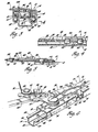
- a seat slide structure 10 includes an upper track member 12 and a lower track member 14.
- the upper track member 12 includes a base wall 16, a pair of laterally extending side walls 18 and a pair of terminal flanges 20 of arcuate shape, Figure 3.
- the lower track member 14 includes a base wall 22, a pair of side walls 24, and terminal flanges 26 which are arcuate. Base wall 22, side walls 24 and terminal flanges 26 are located in opposed spaced relationship to like base wall 16, side walls 18 and terminal flanges 20 of the upper track member 12.
- the track member 12 is supported on the track member 14 for horizontal adjustment relative thereto by a bearing assembly 27 which may be conventional or of the type shown in our copending application, No. (MJD/1772) filed
- One of the side walls 24 of the lower track member 14 is provided with a longitudinal series of openings 28, a successive pair of which are alignable with a pair of openings 30 in the free edge of the one terminal flange 20 of the upper track member 12 which opposes the one side wall 24 of the lower track member, Figures 3, 4 and 6.
- a latch structure includes a latch member 36 which is pivoted at 38 to the base wall 16 and includes a latch portion 40 which extends generally laterally to the latch member and inwardly of the track member 12 through the opening 32.
- the latch portion 40 terminates in a pair of latch teeth 42 which extend laterally and which are spaced apart the same distance as the successive pairs of openings 28 and the openings 30.
- a wire spring member 44 is anchored to the latch member 36 by integral lanced bent tabs 46 and 4 8 , the former of which is slightly arcuate.
- Wire spring member 44 has an offset bent end 50 which extends inwardly of the track member 12 through the extension 34 of opening 32 so that the wire spring member is anchored between the latch member 36 and the upper track member 12.
- the wire spring member 44 biases the latch member 36 clockwise as viewed in Figures 2 and 6 to the latched position wherein the latch portion 40 engages one of the side edges of the opening 32.
- release means such as a suitable handle or other operator would be welded or otherwise secured to the latch member 36 so as to move the latch member to a released position by rotating it counterclockwise about the pivot 38 against the bias of the wire spring member 44. This would move the latch teeth 42 out of engagement with the openings 28 and 30 to permit horizontal adjusting movement of the upper track member 12 relative to the lower track member 14.
- the release means includes a flexible cable 52 which has each end thereof provided with a cylindrical abutment 54 which is secured within a slot 56 of a reversely bent integral ear 58 of each of the latch members 36 to anchor the ends of the flexible cable.
- the flexible cable 52 is slightly slack between its anchored ends.
- a release lever 60 is coaxially pivoted with one of the latch members 36 on the pivot 38.
- the release lever 60 has a slightly offset end as shown in Figure 5 which pivotally mounts a pulley 62 at pivot 64.
- the pulley 62 is grooved and is engageable with the flexible cable 52 intermediate the anchored ends thereof.
- a manually operative handle 66 is riveted at 68 to the release lever 60 to effect counterclockwise rotation thereof. When it is desired to horizontally adjust the seat secured to the spaced track members 12, the manually operative handle 66 is operated to rotate the release lever 60 slightly counterclockwise to its position shown in dash lines in Figure 2.
- the pulley 62 pivotally shortens the flexible cable 52 intermediate its anchored ends so that both of the latch members 36 are simultaneously rotated about their respective pivots 38 to the released position to free the upper track members 12 for simultaneous horizontal adjustment to a new position.
- this invention provides an improved latch structure for a seat slide structure and an improved release arrangement for latch structures of spaced seat slide structures mounting a seat on a vehicle.
Landscapes
- Engineering & Computer Science (AREA)
- Aviation & Aerospace Engineering (AREA)
- Transportation (AREA)
- Mechanical Engineering (AREA)
- Seats For Vehicles (AREA)
Applications Claiming Priority (2)
| Application Number | Priority Date | Filing Date | Title |
|---|---|---|---|
| US06/710,289 US4580755A (en) | 1985-03-11 | 1985-03-11 | Latch arrangement for a seat slide structure |
| US710289 | 1985-03-11 |
Publications (1)
| Publication Number | Publication Date |
|---|---|
| EP0194754A2 true EP0194754A2 (de) | 1986-09-17 |
Family
ID=24853408
Family Applications (1)
| Application Number | Title | Priority Date | Filing Date |
|---|---|---|---|
| EP86300908A Withdrawn EP0194754A2 (de) | 1985-03-11 | 1986-02-11 | Sitzgleitkonstruktion und Feststellkonstruktion dafür |
Country Status (3)
| Country | Link |
|---|---|
| US (1) | US4580755A (de) |
| EP (1) | EP0194754A2 (de) |
| JP (1) | JPS61207238A (de) |
Cited By (2)
| Publication number | Priority date | Publication date | Assignee | Title |
|---|---|---|---|---|
| GB2302802A (en) * | 1995-06-30 | 1997-02-05 | Aisin Seiki | A seat slide mechanism for a vehicle |
| EP0475536B1 (de) * | 1987-01-29 | 1997-04-02 | Takeda Chemical Industries, Ltd. | Kugelförmige Granula mit Kern sowie deren Herstellung |
Families Citing this family (14)
| Publication number | Priority date | Publication date | Assignee | Title |
|---|---|---|---|---|
| JPH0615312B2 (ja) * | 1986-04-07 | 1994-03-02 | 株式会社大井製作所 | 自動車用シートスライド装置 |
| JPH0332430Y2 (de) * | 1986-10-07 | 1991-07-10 | ||
| US4881827A (en) * | 1988-03-02 | 1989-11-21 | General Motors Corporation | Apparatus and method of anti-ratcheting vehicle seat adjuster slide |
| JPH059227Y2 (de) * | 1988-07-28 | 1993-03-08 | ||
| US5172882A (en) * | 1991-03-25 | 1992-12-22 | General Motors Corporation | Manual seat adjuster with dual locking means |
| US5292164A (en) * | 1992-12-23 | 1994-03-08 | Itt Corporation | Power seat adjuster with horizontal slot drive |
| US5499788A (en) * | 1993-03-31 | 1996-03-19 | Itt Corporation | Manual seat adjuster |
| US5344114A (en) * | 1993-03-31 | 1994-09-06 | Itt Corporation | Vehicle seat adjuster |
| NO932534L (no) * | 1993-07-12 | 1995-01-13 | Norsk Hydro As | Et system for låsing og tilpassing av bilseter |
| US5425522A (en) * | 1994-04-13 | 1995-06-20 | Atwood Industries, Inc. | Vehicle seat adjuster with conveniently accessible rotary actuator |
| US5520362A (en) * | 1994-05-06 | 1996-05-28 | General Motors Corporation | Master-slave vehicle seat adjuster |
| JP3757320B2 (ja) * | 1995-07-19 | 2006-03-22 | カイペル・ゲゼルシヤフト・ミツト・ベシユレンクテル ハフツング・ウント・コンパニ− | 自動車の座席を長手方向に調節する装置 |
| JP2001138778A (ja) * | 1999-11-16 | 2001-05-22 | Aisin Seiki Co Ltd | シートスライド装置 |
| JP2008049891A (ja) * | 2006-08-25 | 2008-03-06 | Aisin Seiki Co Ltd | 車両用シートスライド装置 |
Family Cites Families (11)
| Publication number | Priority date | Publication date | Assignee | Title |
|---|---|---|---|---|
| US3524677A (en) * | 1968-08-26 | 1970-08-18 | Gen Motors Corp | Vehicle seat latch |
| JPS5047319A (de) * | 1973-08-31 | 1975-04-26 | ||
| US4004772A (en) * | 1975-01-30 | 1977-01-25 | Ferro Manufacturing Corporation | Manual seat adjuster |
| NL7608003A (nl) * | 1976-07-20 | 1978-01-24 | Philips Nv | Magnetische inrichting met domeinen. |
| GB1602844A (en) * | 1977-03-24 | 1981-11-18 | Brown Bros Eng Ltd | Vehicle seat slides |
| FR2415024A1 (fr) * | 1978-01-18 | 1979-08-17 | Faure Bertrand | Perfectionnements aux glissieres de support de sieges |
| US4169574A (en) * | 1978-02-23 | 1979-10-02 | General Motors Corporation | Vehicle seat mounting arrangement |
| US4262963A (en) * | 1979-05-21 | 1981-04-21 | C. Rob. Hammerstein Gmbh | Guide rail assembly for a vehicle seat |
| JPS5631839A (en) * | 1979-08-22 | 1981-03-31 | Aisin Seiki Co Ltd | One-step feeding system seat sliding adjuster |
| JPS57110535A (en) * | 1980-12-26 | 1982-07-09 | Nissan Motor Co Ltd | Walk-in device for seat of vehicle |
| JPS5852847A (ja) * | 1981-09-25 | 1983-03-29 | Hitachi Ltd | 配線の形成方法 |
-
1985
- 1985-03-11 US US06/710,289 patent/US4580755A/en not_active Expired - Fee Related
-
1986
- 1986-02-11 EP EP86300908A patent/EP0194754A2/de not_active Withdrawn
- 1986-03-11 JP JP61051625A patent/JPS61207238A/ja active Pending
Cited By (4)
| Publication number | Priority date | Publication date | Assignee | Title |
|---|---|---|---|---|
| EP0475536B1 (de) * | 1987-01-29 | 1997-04-02 | Takeda Chemical Industries, Ltd. | Kugelförmige Granula mit Kern sowie deren Herstellung |
| GB2302802A (en) * | 1995-06-30 | 1997-02-05 | Aisin Seiki | A seat slide mechanism for a vehicle |
| US5775662A (en) * | 1995-06-30 | 1998-07-07 | Aisin Seiki Kabushiki Kaisha | Seat sliding mechanism provided with play mechanism |
| GB2302802B (en) * | 1995-06-30 | 1999-03-31 | Aisin Seiki | A seat sliding mechanism |
Also Published As
| Publication number | Publication date |
|---|---|
| US4580755A (en) | 1986-04-08 |
| JPS61207238A (ja) | 1986-09-13 |
Similar Documents
| Publication | Publication Date | Title |
|---|---|---|
| EP0194754A2 (de) | Sitzgleitkonstruktion und Feststellkonstruktion dafür | |
| US4530481A (en) | Seat rail | |
| US5330245A (en) | Movable vehicle seat | |
| JP3636515B2 (ja) | 車両座席の背もたれ用ヒンジ装置 | |
| JP3947882B2 (ja) | 自動車用ヘッドレストの前後進装置 | |
| US5707092A (en) | Self-aligning loop striker | |
| CA2025708C (en) | Stirrup assembly for examination table | |
| EP0201163A2 (de) | Vorrichtung zum Einstellen eines Sitzes zum Erleichtern des Zugangs | |
| EP0411850A2 (de) | Fahrzeugsitzverstellvorrichtung | |
| EP0195508A2 (de) | Sitzschienenaufbau und Verriegelungsaufbau dafür | |
| EP0812722A2 (de) | Drehbare Vorrichtung für Kraftfahrzeugsitze | |
| JP2001309832A (ja) | 乗物用シートのヒンジ機構およびそのような機構が取り付けられたシート | |
| KR20000029792A (ko) | 창문조정기장착용판넬 | |
| US4364602A (en) | Seat support structure for the driving of an earth moving machine | |
| ES251619U (es) | Dispositivo para el ajuste de la inclinacion relativa de dos organos,especialmente de las dos partes de un asiento de vehiculo automovil | |
| EP0196773A2 (de) | Vorrichtung zum Einstellen eines Sitzes zum Erleichtern des Zugangs | |
| US4438895A (en) | Vertical seat adjuster for vehicle seats | |
| EP0505090A1 (de) | Kupplungsanordnung zur Handverstellung eines Sitzes | |
| JPH0461646B2 (de) | ||
| US4572469A (en) | Latching arrangement for seat slide structures | |
| US4113309A (en) | Headrest for dental chair | |
| US5338093A (en) | Seat reclining apparatus | |
| GB1597020A (en) | Hinge device | |
| US4463922A (en) | Seat slide structure | |
| EP0911208B1 (de) | Sitzverstellvorrichtung |
Legal Events
| Date | Code | Title | Description |
|---|---|---|---|
| PUAI | Public reference made under article 153(3) epc to a published international application that has entered the european phase |
Free format text: ORIGINAL CODE: 0009012 |
|
| 17P | Request for examination filed |
Effective date: 19860221 |
|
| AK | Designated contracting states |
Kind code of ref document: A2 Designated state(s): DE GB |
|
| STAA | Information on the status of an ep patent application or granted ep patent |
Free format text: STATUS: THE APPLICATION HAS BEEN WITHDRAWN |
|
| 18W | Application withdrawn |
Withdrawal date: 19871023 |
|
| RIN1 | Information on inventor provided before grant (corrected) |
Inventor name: REES, RICHARD ARTHUR |