EP0194892B1 - Protected refrigerator compressor motor systems - Google Patents
Protected refrigerator compressor motor systems Download PDFInfo
- Publication number
- EP0194892B1 EP0194892B1 EP86301857A EP86301857A EP0194892B1 EP 0194892 B1 EP0194892 B1 EP 0194892B1 EP 86301857 A EP86301857 A EP 86301857A EP 86301857 A EP86301857 A EP 86301857A EP 0194892 B1 EP0194892 B1 EP 0194892B1
- Authority
- EP
- European Patent Office
- Prior art keywords
- motor
- recess
- heater
- protector
- protector according
- Prior art date
- Legal status (The legal status is an assumption and is not a legal conclusion. Google has not performed a legal analysis and makes no representation as to the accuracy of the status listed.)
- Expired - Lifetime
Links
Images


Classifications
-
- H—ELECTRICITY
- H02—GENERATION; CONVERSION OR DISTRIBUTION OF ELECTRIC POWER
- H02H—EMERGENCY PROTECTIVE CIRCUIT ARRANGEMENTS
- H02H3/00—Emergency protective circuit arrangements for automatic disconnection directly responsive to an undesired change from normal electric working condition with or without subsequent reconnection ; integrated protection
- H02H3/08—Emergency protective circuit arrangements for automatic disconnection directly responsive to an undesired change from normal electric working condition with or without subsequent reconnection ; integrated protection responsive to excess current
-
- H—ELECTRICITY
- H01—ELECTRIC ELEMENTS
- H01H—ELECTRIC SWITCHES; RELAYS; SELECTORS; EMERGENCY PROTECTIVE DEVICES
- H01H61/00—Electrothermal relays
- H01H61/002—Structural combination of a time delay electrothermal relay with an electrothermal protective relay, e.g. a start relay
-
- F—MECHANICAL ENGINEERING; LIGHTING; HEATING; WEAPONS; BLASTING
- F25—REFRIGERATION OR COOLING; COMBINED HEATING AND REFRIGERATION SYSTEMS; HEAT PUMP SYSTEMS; MANUFACTURE OR STORAGE OF ICE; LIQUEFACTION SOLIDIFICATION OF GASES
- F25B—REFRIGERATION MACHINES, PLANTS OR SYSTEMS; COMBINED HEATING AND REFRIGERATION SYSTEMS; HEAT PUMP SYSTEMS
- F25B2400/00—Component parts or details not otherwise provided for in this subclass
- F25B2400/07—Details of compressors or related parts
- F25B2400/077—Compressor control units, e.g. terminal boxes, mounted on the compressor casing wall containing for example starter, protection switches or connector contacts
-
- H—ELECTRICITY
- H01—ELECTRIC ELEMENTS
- H01H—ELECTRIC SWITCHES; RELAYS; SELECTORS; EMERGENCY PROTECTIVE DEVICES
- H01H37/00—Thermally-actuated switches
- H01H37/02—Details
- H01H37/32—Thermally-sensitive members
- H01H37/52—Thermally-sensitive members actuated due to deflection of bimetallic element
- H01H37/54—Thermally-sensitive members actuated due to deflection of bimetallic element wherein the bimetallic element is inherently snap acting
- H01H37/5427—Thermally-sensitive members actuated due to deflection of bimetallic element wherein the bimetallic element is inherently snap acting encapsulated in sealed miniaturised housing
-
- H—ELECTRICITY
- H01—ELECTRIC ELEMENTS
- H01H—ELECTRIC SWITCHES; RELAYS; SELECTORS; EMERGENCY PROTECTIVE DEVICES
- H01H81/00—Protective switches in which contacts are normally closed but are repeatedly opened and reclosed as long as a condition causing excess current persists, e.g. for current limiting
- H01H81/02—Protective switches in which contacts are normally closed but are repeatedly opened and reclosed as long as a condition causing excess current persists, e.g. for current limiting electrothermally operated
Definitions
- the field of this invention is that of motor protectors and the invention relates more particularly to a refrigerator compressor motor system having inherent motor overload protection and to motor protectors for use in such a system.
- Thermostat metal motor protectors adapted to provide what is called inherent motor overload protection are well known. Such protectors are both current and temperature responsive and provide both short time (locked rotor) and ultimate trip (running overload) protection to prevent overheating of motors due either to large, sharp motor overloads of brief duration or to smaller motor overloads of longer duration.
- a dished thermostat metal means is arranged to have selected thermal coupling to an electrical motor when the protector is mounted in its intended position on the motor.
- the protector also has an electrical resistance heater system which is connected in series with the motor to carry the motor current for heating the thermostat metal means in response to current flowing in the heater system.
- the combined heating effect from thermal coupling to the motor and from the electrical heater system is such that the thermostat metal means remains unactuated to maintain normal motor operation.
- those combined heating effects heat the thermostat metal means to a selected actuating temperature so it moves to an inverted dished configuration with snap action to separate protector contacts and interrupt operation of the motor.
- the ultimate trip characteristic of the protector governs and the protector is typically actuated in response to the combined heating effect of heat transfer from the motor and from a small overload current in the resistance heater system of the protector, thereby to provide what is called running overload protection for the motor.
- a fault condition such as a locked rotor occurs, this results in a large, sharp increase in motor current such as would tend to cause a rapid rise in the motor temperature.
- the short time trip characteristic of the protector governs and the protector is actuated primarily in response to the increase in motor current in the resistance heater system of the protector to interrupt motor operation before the anticipated overheating of the motor occurs, thereby to provide what is called locked rotor protection for the motor.
- the thermostat metal means subsequently cools to a relatively lower, reset temperature and returns with snap action to its original dished configuration so that, if the fault condition has been corrected during the off-time provided by the protector, normal running operation of the motor is resumed. However, if the fault condition persists, the protector cycles on and off in the manner described for a sufficient period of time without damage to the motor to permit operator intervention to correct the fault condition.
- the thermostat metal means used in the protector has desirably had a relatively low reset temperature which was selected to provide an off-time characteristic allowing a period for operator intervention which is consistent with the practical cycle life of electrical contacts and other components in the protector.
- motor temperature occurring during overheating could exceed the temperature limits of insulation materials used in the motor windings.
- Protector cycling on and off during the continuation of a fault condition in the motor could exceed the cycle life of electrical contacts or other components used in the protectors.
- specifications for motors and motor protectors are typically prescribed in codes established by testing services and industry associations and by governmental bodies and the like in different countries to assure that the motors and protectors have the properties necessary to meet the requirements of various applications. While different codes establish specifications in different terms, the specifications are typically intended to meet related requirements and therefore tend to have similar features.
- the protectors are usually provided with a selected combination of short time (locked rotor) trip and ultimate (running overload) trip characteristics to achieve the desired protection.
- the desired performance characteristics for inherent motor protectors of a particular manufacturer or group of suppliers may be defined by reference to the short time (locked rotor) trip current necessary for tripping the motor protector within a specified short trip time and by reference to the ultimate trip (running overload) current for tripping the protector assuming the current and heat transfer to the thermostat metal means are stabilized at a selected, constant level.
- the inherent characteristics of a group of motor protectors available for use in a particular category of commercial applications are defined by reference to the short time trip current for a short trip time of ten (10) seconds and to the stabilized ultimate trip current (usually determined by incrementally increasing the current at intervals of about 15 minutes) where the effective protector ambient (the ambient determined for the thermostat metal means during normal full load running operation of the motor) is taken to be 65 o C., those characteristics typically being referenced in more general terms by expressing the characteristic as a ratio of such short time trip and ultimate trip currents.
- Inherent motor protectors having performance characteristics defined generally within particular ranges in this manner are then applied to specific motors with respect to the rate of temperature rise and the maximum permitted temperatures of the motor windings and the like by the use of bench tests, thereby to selectively match individual protectors to the motors to meet the code requirements for those motors and for providing the desired inherent overload protection for individual motors likely to be encountered.
- the thermostat metal means in the protector has been provided with selected electrical resistance properties and has been incorporated in the motor circuit as part of the resistance heater system of the protector. That is, in providing sufficient heating for the thermostat metal means to actuate the protector under each of the various different motor overload conditions likely to be encountered, it has been found that, because of heat transfer effects, the heat generated directly in a thermostat metal means having selected electrical resistance properties is more promptly effective than heat transferred from the motor or from other resistance heater means for raising the temperature of the thermostat metal means. Further, the heating effect of the resistance in the thermostat metal means has typically been needed for meeting the complex heating patterns required to provide the desired range of motor protection.
- thermostat metal means has had to be connected in the motor circuit and the need for making electrical connection to the thermostat metal actuating means by electrical contacts or supports or the like has meant that the thermal response characteristics initially provided in the dished thermostat metal means had tended to be altered during protector assembly.
- calibration of the protector has usually been required after protector assembly for meeting motor protection requirements.
- motor protectors have typically had relatively complex and expensive structures and have usually required complex manufacturing and calibration processes. It would be desirable if the advantages of an inherent motor overload protector could be achieved utilizing a relatively less complex and less expensive motor protector device and a more convenient device assembly procedure while still meeting the demanding requirements of today's industry.
- thermally operated switches for protecting electric motors in which the motor current passes through an electric resistance heater and the heat so generated falls on a bimetallic snap-action-disc element that is held in the housing close to the heater and which, when it is heated sufficiently, flexes to move a switch contact on the element away from a fixed contact.
- a current and temperature responsive motor protector organized and arranged to be mounted in a particular manner on an electric motor to provide in use short time trip and ultimate trip protection of the motor
- the protector comprising: a base, first contact means mounted on the base engaged with complementary contact means when in its normal first position so that in use a supply circuit to the motor is closed, the complementary contact means being movable to a second position to disengage the first contact means to open the supply circuit to the motor, thermostat metal means comprising a dished snap-acting thermostat metal member having an original dished configuration and an inverted dished configuration, the member changing from the original dished configuration to the inverted dished configuration when heated to a precise actuating temperature, and being mounted on the base so as to be disposed to have particular thermal coupling to the motor when the protector is mounted on the motor in the particular manner, and electrical resistance heater means connected so that in use current to the motor passes through it and disposed so that in use it cooperates with the heating of the thermostat metal means by the motor so as to permit
- a motor protector can provide inherent overload protection for compressor motors as used in home refrigerator appliances. Such a motor protector and system may have a relatively less complex and expensive structure.
- a series of inherent motor protectors particularly adapted for refrigerator compressor motor systems can be provided wherein characteristics of the protectors in the series differ in selected increments so that protectors selected from the series are adapted for use in providing inherent overload protection for motors in refrigerator compressor systems likely to be encountered in a commercially recognized category such as home refrigerator appliances.
- Systems with solid state PTC motor starters having resistance switching means of positive temperature coefficient of resistivity may be provided, where the protectors have improved reset times compatible with the reset times of the motor starters.
- protectors used in providing inherent motor overload protection for hermetically sealed refrigerator compressor motors in home refrigerator appliances typically have short time (locked rotor) trip currents and ultimate (running overload) trip currents as commonly specified above with ratios of such currents in the range from 2.5 to 3.5 for certain motor systems and in the range from 3.5 to 4.5 for the remaining motor systems.
- the current ratios are found to be in the lower range where the compressor motors are of the type operable at 110 volts requiring current-responsive motor starting using electromechanical motor starting relays or the like and are in the upper range where other starting relay means such as positive temperature coefficient resistance starter relays for split-phase motors or the like operable at 220 volts are used. It has also now been found that where the protector components are arranged in a particular way, such short time trip/ultimate trip current ratios are achieved by a thermostat metal actuator means that is disposed outside the motor winding circuit and where it is adapted to be precisely assembled in the protector to provide the desired inherent overload protection characteristics without requiring calibration of the protector after protector assembly or after incorporation in a refrigerator compressor motor system.
- an example of a novel and improved refrigerator compressor motor system having improved inherent motor protection comprises an electrical motor and a refrigerator compressor operated by the motor hermetically sealed in a common shell, and a current and temperature responsive motor protector providing short time trip and ultimate trip protection for the motor.
- the systems include electromechanical motor starting relays or resistance starting relays of positive temperature coefficient of resistivity as may be desired.
- the protector may comprise base means, contact means mounted on the base means for relative movement between positions opening and closing the motor circuit, and thermostat metal means adapted to move from an original dished configuration to an inverted dished configuration with snap action when the thermostat metal means is heated to a selected actuation temperature.
- the thermostat metal means is adapted to return to its original dished configuration with snap action when it is subsequently cooled to a relatively lower reset temperature.
- the thermostat metal means is mounted on the base means of the protector to move the contact means between said circuit opening and closing positions in response to movement of the thermostat metal means between said dished configurations.
- the thermostat metal means is thermally coupled in selected heat-transfer relation to the electrical motor but located outside the motor circuit so motor current is not directed through the thermostat metal means.
- resistance heater means responsive to motor current are arranged to transfer selected heat to the thermostat metal means in such a way as to cooperate with the thermal coupling of the thermostat metal means to the motor to provide both short time trip and ultimate trip protection for the motor.
- the base means may be of an electrical insulating material of relatively low thermal conductivity and with a recess therein.
- a boss of the base material of low thermal conductivity extends up into the recess to provide the base means with additional heat sink capacity.
- the heater means is disposed within the recess and preferably surrounds the boss of the base material provided in the center of the recess.
- heater is preferably formed of a wire material such as nickel having a selected positive temperature coefficient of resistivity.
- the thermostat metal means comprises a round thermostat metal disc which is disposed in the recess on a recess shoulder to extend over the heater means in close thermal coupling to the heater means to be normally free of externally applied stress within the recess.
- Tee protector also includes fixed contact means which are mounted on the base means outside the recess and a resilient, movable contact arm which extends over the recess where it is adapted to normally retain the thermostat metal disc in the recess free of applied stress.
- the movable contact arm normally engages the fixed contact means for closing the motor circuit and the arm is movable by movement of the thermostat disc to its inverted dished configuration to disengage the arm from the fixed contact means to open the motor circuit.
- the movable contact arm also returns to its circuit closing position when the thermostat disc subsequently cools and snaps back to its original dished configuration.
- Terminal means electrically connected to the respective fixed and movable contact means extend from the base means for electrically connecting the motor protector in the electrical motor circuit.
- the recess in the protector base means has an end which opens at one side of the base, has a recess bottom and a side wall, has a shoulder in the side wall facing the open end of the recess, and has another opening in the recess side wall.
- That side of the base means also has grooves and reference surfaces formed therein for receiving and accurately positioning the heater means, thermostat metal means, contact means and terminal means of the protector in predetermined relation to each other on the base means.
- the heating capacity of the electrical heater means may be regulated with respect to the thermal conductivity and capacity of the thermostat metal disc, the base means and the other protector components for providing the protector with a ratio of short time trip current (for short time of ten seconds) and ultimate trip current (stabilized) in the range from 2.5 to 4.5 where the effective protector ambient temperature is 65 o C..
- a series of such motor protectors is provided for use in refrigerator compressor motor systems for home refrigerator appliances to provide both short time trip and ultimate trip protection in such systems as are likely to be encountered, the series preferably having heaters with current ratings in the range from one to ten amperes wherein the current ratings of the individual heaters are separated by increments corresponding to about 5 percent of the current rating of the next lower heater current rating in the series and preferably having thermostat metal disc actuating temperatures in the range from about 90 o C. to 160 o C. separated in increments of about 5 o C..
- the thermal capacity of the protectors of the described structure are regulated for providing reset times for some of the protectors in a range the upper limit of which is at least greater than about 150 seconds for permitting use of the protectors in refrigerator compressor motor systems utilizing motor starters having resistance switching means of positive temperature coefficient of resistivity to be compatible with the reset times of such starters.
- the protector bases, contacts, terminals, heaters and thermostat metal disc means are adapted for easy manufacture and assembly.
- the thermostat metal disc is not required to display any selected electrical resistivity and does not require any wide differential between its actuating and reset temperatures so it is easily manufactured to display precisely predetermined thermal response characteristics when it is free of externally applied forces.
- the thermostat metal disc is then assembled in the protector, it does not have to be welded, clamped or pig tailed in any electrical circuit and is accordingly mounted on the protector base free of such externally applied forces wherein it is adapted to display those precisely predetermined thermal response characteristics for opening and closing the motor circuit.
- the thermostat metal disc is not connected in the motor circuit, it is adapted to be disposed in close thermal coupling to a separate electrical resistance heater means and to be closely accommodated between the heater means and a resilient contact arm which is series connected with the heater means and at the same polarity as the heater means, thereby to move the contact arm between positions opening and closing the motor circuit without requiring heavy motion transfer means or the like.
- the thermostat metal disc is easily proportioned and thermally coupled relative to the motor and to the separate heater means to provide short time trip to ultimate trip current ratios in the range from 2.3 to 4.5 to meet the stringent requirements for use in refrigerator compressor motor systems for home refrigerator appliances and the like.
- the protectors are also adapted to display reset times in such motor systems which are compatible with use of the newer resistance types of motor starting relays having resistance switching means of positive temperature coefficient of resistivity which require significant periods of time for reset during system cycling while a fault condition persists.
- the resilient contact arm in the protector is not subjected to creep type movement during heating and cooling of the thermostat metal means at temperatures below the actuating temperatures thereof, the resilience of the contact arm is easily selected to provide accurately predetermined contact pressures in the protector for achieving improved protector service life.
- the structure of the protector is adapted for precise accurate and inexpensive assembly for achieving the high quality standards required by today's industry.
- a refrigerator compressor motor system which is shown to include a conventional sealed compressor unit 12, a motor protector 14 as provided by this invention, and a conventional PTC motor starting means 16.
- the sealed compressor unit incorporates a conventional electrical motor 18 and a refrigerator compressor 20 operated by the motor which are hermetically sealed in a common metal shell 22.
- the unit is mounted in any conventional manner in any home refrigerator appliance (as defined above) for example as is diagrammatically illustrated at 24 in Fig. 1.
- Thermally and electrically conductive lead-through pins 26.1, 26.2 and 26.3 are electrically insulated from the shell and from each other by glass seal means 28 or the like to extend in sealed relation through the shell to make electrical connection to the windings of the electrical motor in the shell.
- the motor typically includes a main winding 32 and a start winding 34 which are connected at one end to the respective pins 26.1, 26.2 and which are connected in common at their opposite ends to the pin 26.3 as is schematically shown in Fig. 2.
- the motor starting means 16 is is of any conventional type but in one preferred embodiment discussed further below comprises a solid state motor starter having resistance switching means 16.1 of a positive temperature coefficient of resistivity (PTC). As such a motor starter is described in U.S. Patent No. 4,241,370 incorporated herein by this reference, that starter is not further described herein and it will be understood that any conventional solid state or electromechanical motor starting relay is used in the system 10 within the scope of this invention.
- the motor protector 14 provides inherent motor overload protection for the motor 18 and for that purpose is mounted on the lead-through pin 26.3 in the illustrated manner to be disposed in selected thermally coupled relation to the motor 18 as is described in U.S. Patent Application Serial No. 551,619 filed November 14, 1983 and as is further described below.
- the refrigerator compressor motor system 10 preferably incorporates a fractional horsepower motor 18, motors with ratings in the range from 1/20 to 1/3 horsepower being typically used in home refrigerator appliances.
- the protector 14 is adapted to provide inherent motor overload protection to protect against overheating under either short time trip or ultimate trip motor fault conditions as specified for example in Table I: Table I Type of Protector Maximum Compressor Shell Temperature Spread Thin Over Thin Area Automatically Reset 150 o C.
- the motor protector 14 includes a housing 15 comprising a base or body 38 and a cover 39 which are molded or otherwise formed of an electrically-insulating, glass-filled nylon material or the like having a relatively low thermal conductivity. See Figs. 1-4. Thermally and current responsive switching means are disposed within the housing and the housing is particularly adapted for mounting on a refrigerator compressor unit with any conventional starting means 16 being used in the system in the manner described in the patent application noted above.
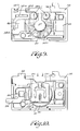
- the base has a recess 40 opening at one side 38.1 of the base as shown in Fig. 5.
- the recess has has a bottom 40.1 and a side wall 40.2 and a shoulder 42 in the side wall faces the open end of the recess.
- a first reference surface 44 is located on the base side 38.1 at one side of the recess and a second reference 46 is located on the same base side at the opposite side of the recess. If desired, ridges 40.3 form locating surfaces on the recess bottom.
- An opening 40.4 in the recess side wall communicates with a groove or channel 38.2 formed in the base side 38.1 and preferably additional grooves 38.3, 38.4 are located in predetermined relation to each other and to the recess 40.
- Preferably access openings 38.5 are located in the groove 38.2 near the recess side wall opening 40.4 and in the reference surface 46 while conductor mounting and locating holes 38.6 are provided in the groove 38.2 and in the reference surfaces 44 and 46.
- a ridge 38.7 extends around part of the base perimeter to cooperate with a corresponding ridge (not shown) on the cover 39 to facilitate mounting of the cover and, if desired, locating pins 39.1 on the cover (one is shown in Fig. 8) fit into locating holes 38.8 in the base. Slots 38.9 in the base ridge communicate with the grooves 38.2 and 38.4 In an alternate embodiment illustrated in Fig.
- a boss 47 of the base material is formed, preferably integral with the base by molding or the like, in the center of the recess bottom upstanding from the bottom so the boss periphery 47.1 is spaced from the recess side wall 40.2 and so that the boss increases the thermal capacity of the base at a location within the base recess.
- the base or body 38 is easily formed by molding or the like and where the recess, recess shoulder, reference surfaces and grooves and the like are all formed in the same base side they are easily formed in precisely predetermined locations relative to each other.
- a first electrical conductor member 48 of cold roll steel or the like is disposed in the groove 38.2 with one end 48.1 extending over an access opening 38.5 near the recess side wall opening 40.4 and with its opposite, terminal end 48.2 extending from the groove through a slot 38.9.
- a tab 48.3 is fitted into a terminal locating hole 38.6 and is staked (bent or bifurcated or the like in conventional manner) in the hole for securing the conductor member 48 in a selected location in the groove.
- the member has a portion 48.4 of limited cross section selected for limiting heat-transfer through the member and that portion is preferably bent to accommodate it in the groove 38.2 as shown.
- An exterior terminal 50 is preferably welded to the terminal end 48.2 as indicated at 50.1 in Fig. 7 and weld projections such as ribs 48.5 are preferably provided on the member end 48.1.
- a second electrical conductor member 52 is also disposed in part of groove 38.2 with one end 52.1 extending over a corresponding access opening 38.5 near the recess side wall opening 40.4 and with its opposite end 52.2 extending into the groove 38.3 over the reference surface 46 and over the window 38.5 in that reference surface.
- This conductor member has weld projections 52.3 at said one end and has a tab 52.4 fitted into and staked in a mounting hole 38.6 for securing the conductor member on the base 38.
- a third electrical conductor member 54 is disposed in the groove 38.3 with one end 54.1 disposed over the reference surface 44 and with an opposite, terminal end 54.2 extending from the groove through a slot 38.9.
- a pair of taps 54.3 fit into and are staked within mounting holes 38.6 for securing the conductor member to the base.
- An exterior terminal 55 is preferably welded to the terminal end 54.2 after mounting of the cover 39 as indicated at 55.1 in Figs. 2 and 4.
- the conductor member 54 has a substantial cross sectional size extending out through the slot 38.9 as illustrated for providing the member with substantial thermal conductivity as will be discussed below. In that construction, the conductor members are easily mounted on the base 38 and are precisely located relative to the base and each other by the grooves, reference surfaces and mounting holes.
- a first or stationary electrical contact 56 is electrically connected to the conductor member 54, preferably by being soldered, brazed or welded to the member to be located at a precisely predetermined position on the base 38 outside the recess 40 at one side of the recess as determined by the reference surface 44, the groove 38.3, and the locating holes 38.6.
- An electrical resistance heating means is disposed in the recess 40 located on the recess bottom against the locating surfaces 40.3.
- the heating means comprises a loop of nichrome or other electrical resistance heating wire or the like which is arranged to extend around the circumference of the recess 40 so that opposite ends of the loop extend over the ends 48.1, and 52.1 of electrical conductors, the heater ends preferably being resistance welded to the respective conductor member ends by means of the weld projections 48.5 and 52.3 where access to the members and heater ends for making the welds is obtained using the access openings 38.5.
- the heater wire 58 is formed of nickel and has a positive temperature coefficient of resistivity such that the resistance of the material increases up to about six times as the temperature of the wire is increased by self-heating or the like.
- the heater wire is wound in an helical coil 58 a and that coil is looped around the boss 47 provided on the base in close heat-transfer relation to that boss, the boss and coil preferably being proportioned as shown so that the coil fits snugly around the boss and tends to be retained in position on the recess bottom by the boss.
- the heater means 58 is also adapted to be connected to the conductor member ends by laser welds as indicated at 58 a .1 in Fig. 9.
- the heater means 58 b is blanked from a sheet of electrical resistance material to be looped within the base recess 40.
- a thermostat metal disc member 60 is disposed in the base recess with the disc perimeter 60.1 resting on the recess shoulder 42 so the disc extends over the heater 58 in closely spaced and predetermined thermally coupled relation to the heater.
- the thermostat disc preferably comprises a round dished member of a multilayer thermostat metal which is normally disposed in the recess 40 in an original, concavo-convex dished configuration with a convex side 60.2 of the disc facing toward the heater as illustrated in Fig. 8 but which is adapted to move to an inverted dished configuration with snap action when the disc is heated to a precisely predetermined actuating temperature while the disc is substantially free of externally applied forces.
- the thermostat metal disc is also adapted to return its original dished configuration with snap action when the disc is subsequently cooled to a relatively lower reset temperature.
- the thermostat disc is disposed in the recess to be normally free of externally applied forces so it is adapted to be actuated when heated to that precisely predetermined actuating temperature.
- the heater is arranged to apply heat more directly to the thermostat 60 at a location at or near the perimeter of the disc preferably at a location extending around at least a major portion of the disc circumference while avoiding application of its more intense heating effect to the center of the disc.
- heating of the disc to its "actuating temperature” actually produces a small temperature differential across the disc but assures that the differential tends to enhance snap acting movement of the disc while tending to reduce such internal stresses in the central portion of the disc which tend to produce substantial drift in the thermal response characteristic of the disc. That is, where the heater is formed of a wire 58 of round cross section as in Fig. 2, or comprises a coil as in Fig. 9, or is formed from a flat sheet material as in Fig.
- the heater 58 is spaced relatively close to the disc around at least a major part of a circumferential portion of the disc 60 while being spaced at a relatively much greater distance from the central portion of the disc for providing some temperature differential between the central and circumferential portions of the disc with the central disc temperature being relatively lower as the disc is heated to a level at which it is actuated to produce snap acting rovement of the disc as noted above.
- the disc is adapted to provide more reliable thermal response than if the central portion of the disc were subjected to relatively higher temperature than circumferential portions of the disc.
- a resilient, electrically conductive, movable contact arm 62 is arranged with one end 62.1 mounted at an opposite side of the base recess 40 so that the arm extends across the open end of the recess and beyond the recess to normally engage the first or complementary stationary contact 56 located outside the base recess.
- the movable contact arm 62 is formed of a copper spring material or the like adapted to provide a relatively low spring rate
- a weld slug or plate 62.2 is secured to the arm end 62.1 by a plurality of resistance weld projections 62.3 or the like
- a movable electrical contact 62.4 is secured to the arm at an opposite end 62.5 of the arm
- a protuberance or dimple 62.6 is provided in the arm intermediate its ends
- stiffening ribs 62.7 are raised from the arm along the length of the arm between the dimple 62.6 and the movable contact arm end 62.5.
- the arm is then welded to the electrical conductor 52 by use of a resistance weld projection 62.7 or the like as shown in Fig.
- the access window 38.5 facilitates forming the weld at 62.7 and a laser weld can be used if preferred.
- the contact arm is precisely located to extend over the thermostat disc to engage the movable contact 62.4 with the complementary contact 56 in a closed circuit position and the dimple is precisely located relative to the disc within the recess.
- the contact pressure between the contacts 62.4 and 56 is easily adjusted by applying an adjusting, bending force to the conductor 52 through the access window 38.5 in the reference surface 46 and, because the arm has a low spring rate and does not normally apply any force to the disc, this contact pressure adjustment is easily made to achieve high contact closing pressures if desired without risk of altering the thermal actuating temperature characteristics of the thermostat disc.
- the noted location of the stiffening ribs 62.7 assures that undesired flexing of the arm is avoided between the dimple and the movable contact 62.4.
- the arm 62 is precisely located relative to the disc 60 and the disc is precisely located relative to the heater by the described structure and the heater and contact arm are electrically connected in series relation to be at the same electrical polarity.
- the disc and heater are easily accommodated in the recess under the arm to be in close relation to achieve desired thermal coupling and to permit the disc to reliably engage the dimple to move the arm to an open circuit position separating the contact 62.4 and 56 when the disc is actuated to move to its inverted dished configuration.
- the heater is a sheet material as shown in Fig. 10 its spacing to the thermostat disc is very small for achieving very effective heat transfer even though the heater rating is viewed by substituting a heater of different serpentine length, that close spacing is reliably retained.
- the position of the arm 62 over the recess also serves to retain or capture the thermostat disc in the recess to retain it in the desired close thermal coupling to the heater 58.
- the cover 39 is cemented or otherwise secured to the base 38 using the ridge 38.7 and the pins 39.1 in locating holes 38.8 and the like.
- additional cover pins 39.2 depend down from the cover into the base recess at respective sides of the contact arm 62 to terminate adjacent peripheral portions of the thermostat disc, thereby to retain the disc in an even more precise thermal coupling and position relative to the heater 58 and arm 62 without normally asserting any externally applied forces on the disc.
- an additional cover pin 39.6 is arranged to depend down to a position in selected spaced relation over the end of the contact arm 62 carrying the movable contact 62.4 to serve as a stop for limiting movement of the arm in opening the motor circuit, thereby to eliminate bouncing of the arm after opening the circuit.
- ridges 39.3 are also preferably provided on the outer side of the cover to define a channel or groove for positioning, supporting and thermally isolating the exterior terminal 55 on the cover outside the cover.
- the exterior terminal 55 has a resilient female compression clip 55.2 arranged at one end so the axis of the female clip extends from the top to the bottom of the protector 14 (as viewed in Fig. 4).
- the clip is therefore adapted to be received axially over the lead-through pin 26.3 for securely gripping the pin to mount the protector 14 with selected thermal coupling to the electrical motor 18 via the terminal 55 and conductor member 54 and with selected spacing from the compressor unit shell 22 as proposed in the patent application noted above.
- the protector cover 39 also preferably has thin tab means 39.4 which are molded integral with the cover of the electrical and thermal insulating material of the cover, which extends from the cover adjacent a bottom edge 14.1 of the protector (see Fig.4) to extend toward and abut the other lead-through pins 26.1, 26.2 for preventing rotation of the protector on the pin 26.3 and for cooperating with the pin 26.3 in locating the protector in a precisely predetermined position on the compressor unit where it will have a precisely predetermined thermal coupling to the compressor motor 18.
- the tab means comprises a pair of tabs spaced from each other at respective ends 14.2 14.3 of the protector to engage portions of the pins 26.1, 26.2 facing away from each other.
- the tabs are adapted to be more universally accommodated under motor starting means 16 of various different designs where the position of the starting means over the tabs assures retention of the protector on the compressor while also tending to minimize the thermal effect such tabs may have with respect to the motor starting means and the like relative to the compressor unit.
- the distal ends of the tabs having guide grooves 39.6 formed in the respective tab means in facing relation to each other facing generally away from the housing for slidably engaging the respective lead-trhough pins 26.1, 26.2 as shown in Fig. 3.
- One starter terminal 16.3 is electrically connected to a power source schematically illustrated at 64 in Fig. 2 while one extension 50.2 of the double, exterior terminal 50 is connected to electrical ground as illustrated at 66 in Fig. 2.
- the initial motor circuit extends through the pin 26.1 to the main winding 32 and through the pin 26.2 and starter resistance 16.1 to the start winding 34, the opposite ends of those windings being connected to the pin 26.3.
- the motor circuit then extends through exterior terminal 55, conductor 54, first contact 56, movable contact 62.4, contact arm 62, conductor 52, heater 58, conductor 48 and exterior protector terminal 50 to electrical ground for energizing the motor windings 32 and 34 to start the motor.
- the starter resistance sharply increases and effectively deenergizes the start winding 34 and also provides protection against overloading of the start winding as will be understood. If no motor fault condition occurs, the normal motor currents in the winding 32 are directed through the protector heater 58 and the protector circuit remains closed, the heater being proportioned so that the combined heating effect of such currents in the heater and of thermal coupling of the protector to the motor is insufficient to heat the thermostat metal disc to its actuating temperature for opening the protector circuit.
- a sharp increase in current is directed through the heater 58 and cooperates with the thermal coupling to the motor to deenergize the motor before heating damage can occur to the motor.
- energizing of the heater is also interrupted but the heater material and other protector components retain a substantial amount of heat within the protector for substantial period of time for retaining a thermostat metal disc above its reset temperature for a substantial period of time even if the reset temperature has been selected to be somewhat high to facilitate manufacture of the disc or the like.
- the protector base has a boss 47 located within the base recess as shown in Fig.
- the motor protector is adapted to cycle the motor on and off for a substantial period of time to protect the motor against damage due to overheating while permitting time for operator intervention to correct any motor fault condition which may exist.
- the components of the motor protector as thus constructed are particularly adapted to be regulated relative to each other for providing a series of motor protectors having thermal response and reset characteristics such that individual protectors selected from the series are adapted to be used for providing protection for any electrical motor likely to be encountered within a particular group or category of electrical motor applications. That is, the heating capacity of the heaters are regulated with respect to thermal capacity of the protector components and the actuating and reset temperatures of the disc 60 to provide the protectors with selected thermal response and reset characteristics.
- the heaters 58 used in the protectors in the series have current ratings arranged from about one to ten amperes with the current ratings of the respective protectors in the series separated from each other by increments corresponding to about 5 percent of the heater current rating of the protector with the next lowest heater current rating in the series.
- the thermostat metal disc members in the series have actuating temperatures in the range from about 90 to 160 o C. separated from each other by increments of about 5 o C. or the like.
- the discs have reset temperatures not less than about 52 o C..
- the proportions of the protector components are then regulated relative to each other and to the selected thermal coupling to the motor to provide each protector with a ratio of short time trip current to ultimate trip current for a short trip time of ten seconds in the range from 2.3 to 4.5 where the effective protector ambient is 65 o C.
- the protector series includes one group having such a ratio in the range from 2.3 to 3.5 for use with 110-115 volt motors using electromechanical motor starting relays and another group in the range from 3.5 to 4.5 for use with 220-230 volt motors using solid state PTC resistance switch motor starting relays.
- the protector components are regulated to provide reset times after short time tripping in the range from abut 30 to 150 or more seconds.
- the series or motor protectors is adapted to provide inherent motor overload protection including both ultimate trip and short time trip protection for any motors likely to be encountered in refrigerator compressor motor systems used in home refrigerator appliances.
- the proportions of the protectors are regulated for use in other motor protector appliances as may be desired.
- the motor starting means 16 comprises a solid state motor starter having resistance switching means 16.1 of positive temperature coefficient resistivity as previously described
- the proportions of the protector components are preferably regulated as described so that the protectors have reset times of at least about 150 seconds duration or the like to exceed the reset times of such starter as are likely to be encountered in the intended motor application category.
- the heater resistance increases in proportion to the increase in motor current and is particularly adapted for achieving short trip times.
- the heater proportions are preferably selected with respect to such temperature coefficient characteristics to display a first relatively low electrical resistance when a normal motor running current is directed through the heater, to display a second relatively higher electrical resistance in response to a relatively higher ultimate trip current being directed through the heater, and to display a third substantially much higher electrical resistance when a sharply increased, short time trip current is directed through the heater, those heater proportions being selected with respect to the thermal coupling to the motor to facilitate matching of the protector characteristics to selected motors to be used with protectors for providing short time trip and ultimate trip protection for the motors.
- Such PTC nickel wire heaters are particularly useful in providing motor protectors of this structure having the relatively low short time trip/ultimate trip current ratios on the order of about 2.3 and for achieving short time trip times of substantially less than 10 seconds or even in the order of abut 3 seconds as applied to particular motors.
Landscapes
- Thermally Actuated Switches (AREA)
- Protection Of Generators And Motors (AREA)
Applications Claiming Priority (2)
| Application Number | Priority Date | Filing Date | Title |
|---|---|---|---|
| IT4781885 | 1985-03-15 | ||
| IT47818/85A IT1181608B (it) | 1985-03-15 | 1985-03-15 | Salvamotore sensibile alla corrente ed alla temperatura e motore che lo incorpora,in particolare per compressori di frigoriferi e simili |
Publications (3)
| Publication Number | Publication Date |
|---|---|
| EP0194892A2 EP0194892A2 (en) | 1986-09-17 |
| EP0194892A3 EP0194892A3 (en) | 1987-04-08 |
| EP0194892B1 true EP0194892B1 (en) | 1993-08-04 |
Family
ID=11262714
Family Applications (1)
| Application Number | Title | Priority Date | Filing Date |
|---|---|---|---|
| EP86301857A Expired - Lifetime EP0194892B1 (en) | 1985-03-15 | 1986-03-14 | Protected refrigerator compressor motor systems |
Country Status (11)
| Country | Link |
|---|---|
| US (3) | US4706152A (it) |
| EP (1) | EP0194892B1 (it) |
| JP (1) | JPH0828167B2 (it) |
| KR (1) | KR930004816B1 (it) |
| AU (3) | AU591391B2 (it) |
| BR (1) | BR8601144A (it) |
| CA (1) | CA1246129A (it) |
| DE (1) | DE3688800T2 (it) |
| HR (1) | HRP920401A2 (it) |
| IT (1) | IT1181608B (it) |
| YU (1) | YU46666B (it) |
Families Citing this family (45)
| Publication number | Priority date | Publication date | Assignee | Title |
|---|---|---|---|---|
| US4748531A (en) * | 1987-02-20 | 1988-05-31 | Tecumseh Products Company | Compressor terminal block and overload protector assembly |
| DE8806648U1 (de) * | 1988-05-20 | 1989-06-22 | Hofsäss, Peter, 7530 Pforzheim | Temperaturschalteinrichtung |
| JPH0749796B2 (ja) * | 1988-09-26 | 1995-05-31 | 三菱電機株式会社 | 密閉形電動圧縮機の保護器 |
| US4862306A (en) * | 1988-12-22 | 1989-08-29 | Texas Instruments Incorporated | Combination motor protector and starter apparatus |
| JP2651002B2 (ja) * | 1989-02-17 | 1997-09-10 | 松下冷機株式会社 | モータの過負荷保護装置 |
| US5021915A (en) * | 1989-10-17 | 1991-06-04 | General Electric Company | Combination starter-protector device and method of assembling same, overload protector and method of assembling same |
| US5053908A (en) * | 1989-11-29 | 1991-10-01 | Texas Instruments Incorporated | Psc motor start system |
| US5055726A (en) * | 1990-11-01 | 1991-10-08 | Texas Instruments Incorporated | Plug-on protector for compressor motor |
| JP2507171B2 (ja) * | 1990-11-06 | 1996-06-12 | 松下冷機株式会社 | モ―タの過負荷保護装置 |
| US5170307A (en) * | 1991-05-31 | 1992-12-08 | Texas Instruments Incorporated | Mounting apparatus for electrical motor control components |
| CA2085202C (en) * | 1992-03-24 | 1996-10-22 | Ricky L. Bunch | Positive temperature coefficient start winding protection |
| US5206622A (en) * | 1992-04-10 | 1993-04-27 | Texas Instruments Incorporated | Protector device with improved bimetal contact assembly and method of making |
| US5729416A (en) * | 1995-05-30 | 1998-03-17 | General Electric Company | Motor starter and protector module |
| US6122154A (en) * | 1997-04-24 | 2000-09-19 | Damerow; Robert William | Motor starting device and protector module with motor starter cut-out switch |
| JPH11353992A (ja) * | 1998-04-07 | 1999-12-24 | Yamada Electric Mfg Co Ltd | サーマルプロテクタ |
| JP2000217314A (ja) * | 1999-01-26 | 2000-08-04 | Mitsubishi Electric Corp | スタ―タ |
| US6674620B2 (en) * | 2000-12-04 | 2004-01-06 | Texas Instruments Incorporated | Hermetic single phase motor protector |
| CN100407558C (zh) * | 2000-12-04 | 2008-07-30 | 巴西船用压缩机有限公司 | 电动马达启动系统的构建装置 |
| US6795283B2 (en) * | 2001-04-20 | 2004-09-21 | Texas Instruments Incorporated | Electricals package integrating run capacitor, motor protector and motor starter |
| ITPC20040005U1 (it) * | 2004-03-09 | 2004-06-09 | Electrica Srl | Dispositivo di avviamento e protezione in particolare per motori di frigoriferi,provvisto di involucro sagomato in modo da mantenere il protettore separato dagli altri componenti |
| US7412842B2 (en) | 2004-04-27 | 2008-08-19 | Emerson Climate Technologies, Inc. | Compressor diagnostic and protection system |
| US7275377B2 (en) | 2004-08-11 | 2007-10-02 | Lawrence Kates | Method and apparatus for monitoring refrigerant-cycle systems |
| US7304561B2 (en) * | 2004-10-12 | 2007-12-04 | Sensata Technologies, Inc. | Motor overload protector |
| KR100698762B1 (ko) * | 2004-11-16 | 2007-03-23 | 센서스앤드컨트롤스코리아 주식회사 | 냉장고 압축기용 접속 패키지 |
| ITPC20050005U1 (it) * | 2005-03-10 | 2006-09-11 | Electrica Srl | Rele' voltmetrico con connettori rigidi atti a collegare il filo della bobina ai terminali faston |
| ITPC20050006U1 (it) * | 2005-03-10 | 2006-09-11 | Electrica Srl | Rele' voltmetrico con base sagomata che presenta incavi atti a costituire sedi per l'inserimento di attacchi tipo "faston" |
| ITPC20050004U1 (it) * | 2005-03-10 | 2006-09-11 | Electrica Srl | Rele' voltmetrico con aggancio migliorato dei terminali |
| US8590325B2 (en) | 2006-07-19 | 2013-11-26 | Emerson Climate Technologies, Inc. | Protection and diagnostic module for a refrigeration system |
| US20080216494A1 (en) | 2006-09-07 | 2008-09-11 | Pham Hung M | Compressor data module |
| US20090037142A1 (en) | 2007-07-30 | 2009-02-05 | Lawrence Kates | Portable method and apparatus for monitoring refrigerant-cycle systems |
| CN100550247C (zh) * | 2007-08-17 | 2009-10-14 | 常熟市名佳电子器材有限公司 | 制冷压缩机用内置式过载保护器 |
| US8393169B2 (en) | 2007-09-19 | 2013-03-12 | Emerson Climate Technologies, Inc. | Refrigeration monitoring system and method |
| US8160827B2 (en) | 2007-11-02 | 2012-04-17 | Emerson Climate Technologies, Inc. | Compressor sensor module |
| US9140728B2 (en) | 2007-11-02 | 2015-09-22 | Emerson Climate Technologies, Inc. | Compressor sensor module |
| JP5203754B2 (ja) * | 2008-03-11 | 2013-06-05 | 株式会社日立産機システム | インバータ圧縮機の制御方法及びインバータ圧縮機 |
| DE102009053013A1 (de) * | 2008-11-18 | 2010-05-20 | Danfoss Compressors Gmbh | Steuereinheit mit integriertem Temperatursensor |
| EP2681497A4 (en) | 2011-02-28 | 2017-05-31 | Emerson Electric Co. | Residential solutions hvac monitoring and diagnosis |
| US8964338B2 (en) | 2012-01-11 | 2015-02-24 | Emerson Climate Technologies, Inc. | System and method for compressor motor protection |
| US9480177B2 (en) | 2012-07-27 | 2016-10-25 | Emerson Climate Technologies, Inc. | Compressor protection module |
| US9310439B2 (en) | 2012-09-25 | 2016-04-12 | Emerson Climate Technologies, Inc. | Compressor having a control and diagnostic module |
| US9803902B2 (en) | 2013-03-15 | 2017-10-31 | Emerson Climate Technologies, Inc. | System for refrigerant charge verification using two condenser coil temperatures |
| WO2014144446A1 (en) | 2013-03-15 | 2014-09-18 | Emerson Electric Co. | Hvac system remote monitoring and diagnosis |
| US9551504B2 (en) | 2013-03-15 | 2017-01-24 | Emerson Electric Co. | HVAC system remote monitoring and diagnosis |
| CA2908362C (en) | 2013-04-05 | 2018-01-16 | Fadi M. Alsaleem | Heat-pump system with refrigerant charge diagnostics |
| CN104752844B (zh) * | 2013-12-25 | 2017-10-20 | 珠海凌达压缩机有限公司 | 压缩机接线装置及具有该接线装置的压缩机 |
Family Cites Families (20)
| Publication number | Priority date | Publication date | Assignee | Title |
|---|---|---|---|---|
| US2298137A (en) * | 1940-09-10 | 1942-10-06 | Westinghouse Electric & Mfg Co | Motor thermostat |
| US2768342A (en) * | 1953-03-09 | 1956-10-23 | Metals & Controls Corp | Motor protective switch |
| FR1254240A (fr) * | 1959-04-15 | 1961-02-17 | Texas Instruments Inc | Interrupteur thermostatique perfectionné |
| DE1940613U (de) * | 1966-02-16 | 1966-06-16 | Necchi Spa | Warmeschutzvorrichtung fuer elektromotoren. |
| US3579167A (en) * | 1966-07-20 | 1971-05-18 | Texas Instruments Inc | Thermostatic switch with improved heater assembly and method of assembling same |
| US3452313A (en) * | 1966-12-19 | 1969-06-24 | Texas Instruments Inc | Snap-acting thermostatic electric switch |
| US3538478A (en) * | 1968-04-12 | 1970-11-03 | Texas Instruments Inc | Motor protector and method of making the same |
| US3656079A (en) * | 1969-10-13 | 1972-04-11 | Essex International Inc | Thermostatic switch |
| US3858140A (en) * | 1973-07-30 | 1974-12-31 | Texas Instruments Inc | Time-delay relay and method of assembling same |
| US4092573A (en) * | 1975-12-22 | 1978-05-30 | Texas Instruments Incorporated | Motor starting and protecting apparatus |
| US4039992A (en) * | 1976-02-19 | 1977-08-02 | Portage Electric Products, Inc. | Non-creep thermostat construction |
| US4241370A (en) | 1978-11-14 | 1980-12-23 | Texas Instruments Incorporated | Thermal relays particularly for starting single-phase asynchronous motors |
| US4237510A (en) * | 1978-12-29 | 1980-12-02 | Texas Instruments Incorporated | Electrical switching apparatus |
| US4365225A (en) * | 1980-05-05 | 1982-12-21 | Texas Instruments Incorporated | Time delay relay with spring clips |
| JPS6019135U (ja) * | 1983-07-18 | 1985-02-08 | 松下冷機株式会社 | 過負荷保護装置 |
| US4646195A (en) * | 1983-11-14 | 1987-02-24 | Texas Instruments Incorporated | Motor protector particularly suited for use with compressor motors |
| US4499517A (en) * | 1983-11-14 | 1985-02-12 | Texas Instruments Incorporated | Motor protector particularly suited for use with compressor motors |
| US4533894A (en) * | 1984-06-18 | 1985-08-06 | Therm-O-Disc, Incorporated | Adjustable bimetal snap disc thermostat with heaters |
| SE454625B (sv) * | 1986-09-26 | 1988-05-16 | Ssab Svenskt Stal Ab | Sett jemte en anordning for att indikera overlast redan vid lyftets start vid lyft i wireupphengd lyftanordning |
| US4748531A (en) * | 1987-02-20 | 1988-05-31 | Tecumseh Products Company | Compressor terminal block and overload protector assembly |
-
1985
- 1985-03-15 IT IT47818/85A patent/IT1181608B/it active
- 1985-11-04 US US06/794,913 patent/US4706152A/en not_active Expired - Lifetime
- 1985-11-04 US US06/794,871 patent/US4701824A/en not_active Expired - Lifetime
- 1985-11-04 US US06/794,876 patent/US4713717A/en not_active Expired - Lifetime
-
1986
- 1986-02-03 AU AU52946/86A patent/AU591391B2/en not_active Expired
- 1986-02-21 YU YU26786A patent/YU46666B/sh unknown
- 1986-03-13 JP JP61053818A patent/JPH0828167B2/ja not_active Expired - Lifetime
- 1986-03-14 EP EP86301857A patent/EP0194892B1/en not_active Expired - Lifetime
- 1986-03-14 DE DE86301857T patent/DE3688800T2/de not_active Expired - Lifetime
- 1986-03-14 KR KR1019860001834A patent/KR930004816B1/ko not_active Expired - Lifetime
- 1986-03-14 CA CA000504152A patent/CA1246129A/en not_active Expired
- 1986-03-14 BR BR8601144A patent/BR8601144A/pt not_active IP Right Cessation
-
1988
- 1988-08-17 AU AU21060/88A patent/AU604365B2/en not_active Ceased
- 1988-08-17 AU AU21062/88A patent/AU601614B2/en not_active Ceased
-
1992
- 1992-09-21 HR HRP920401AA patent/HRP920401A2/hr not_active Application Discontinuation
Also Published As
| Publication number | Publication date |
|---|---|
| KR930004816B1 (ko) | 1993-06-08 |
| DE3688800T2 (de) | 1994-02-10 |
| YU26786A (en) | 1990-10-31 |
| US4713717A (en) | 1987-12-15 |
| AU2106288A (en) | 1988-12-15 |
| BR8601144A (pt) | 1986-11-25 |
| JPH0828167B2 (ja) | 1996-03-21 |
| AU591391B2 (en) | 1989-11-30 |
| IT1181608B (it) | 1987-09-30 |
| YU46666B (sh) | 1994-01-20 |
| IT8547818A1 (it) | 1986-09-15 |
| US4706152A (en) | 1987-11-10 |
| KR860007764A (ko) | 1986-10-17 |
| HRP920401A2 (hr) | 1994-04-30 |
| CA1246129A (en) | 1988-12-06 |
| IT8547818A0 (it) | 1985-03-15 |
| DE3688800D1 (de) | 1993-09-09 |
| JPS61227631A (ja) | 1986-10-09 |
| EP0194892A2 (en) | 1986-09-17 |
| AU601614B2 (en) | 1990-09-13 |
| EP0194892A3 (en) | 1987-04-08 |
| AU604365B2 (en) | 1990-12-13 |
| AU5294686A (en) | 1986-09-18 |
| US4701824A (en) | 1987-10-20 |
| AU2106088A (en) | 1988-12-08 |
Similar Documents
| Publication | Publication Date | Title |
|---|---|---|
| EP0194892B1 (en) | Protected refrigerator compressor motor systems | |
| US4399423A (en) | Miniature electric circuit protector | |
| US4476452A (en) | Motor protector | |
| US4092573A (en) | Motor starting and protecting apparatus | |
| US5367279A (en) | Overcurrent protection device | |
| USRE31367E (en) | Motor starting and protecting apparatus | |
| US7075403B2 (en) | Motor protector particularly useful with hermetic electromotive compressors | |
| CA1098569A (en) | Hermetic thermally operated protector for an electric motor | |
| US3443259A (en) | Creepless snap-acting thermostatic switch | |
| US4136323A (en) | Miniature motor protector | |
| US7102481B2 (en) | Low current electric motor protector | |
| US6674620B2 (en) | Hermetic single phase motor protector | |
| US6995647B2 (en) | Low current electric motor protector | |
| US4458231A (en) | Protector apparatus for dynamoelectric machines | |
| US3946352A (en) | Thermally responsive switch | |
| KR100452855B1 (ko) | 모터 보호 장치 | |
| US4754251A (en) | Thermostatic electric switch and thermal biasing assembly therefor | |
| EP0890967B1 (en) | Motor starting and protecting apparatus | |
| US2587789A (en) | Motor overload protector terminal structure | |
| US3148256A (en) | Snap action thermostatic switches | |
| US2636099A (en) | Thermal overload switch | |
| US6639503B2 (en) | Methods and apparatus for mounting a bimetal coil in a thermostat | |
| US3369093A (en) | Snap acting thermally responsive element with contacts at the periphery thereof in rocking and sliding engagement with corresponding fixed contacts during snap action | |
| JPH0822757A (ja) | 過負荷保護装置 | |
| JPS6124118A (ja) | サ−モスタツトスイツチ |
Legal Events
| Date | Code | Title | Description |
|---|---|---|---|
| PUAI | Public reference made under article 153(3) epc to a published international application that has entered the european phase |
Free format text: ORIGINAL CODE: 0009012 |
|
| AK | Designated contracting states |
Kind code of ref document: A2 Designated state(s): DE FR GB IT NL SE |
|
| PUAL | Search report despatched |
Free format text: ORIGINAL CODE: 0009013 |
|
| AK | Designated contracting states |
Kind code of ref document: A3 Designated state(s): DE FR GB IT NL SE |
|
| 17P | Request for examination filed |
Effective date: 19871005 |
|
| 17Q | First examination report despatched |
Effective date: 19900907 |
|
| GRAA | (expected) grant |
Free format text: ORIGINAL CODE: 0009210 |
|
| AK | Designated contracting states |
Kind code of ref document: B1 Designated state(s): DE FR GB IT NL SE |
|
| PG25 | Lapsed in a contracting state [announced via postgrant information from national office to epo] |
Ref country code: SE Effective date: 19930804 |
|
| ITF | It: translation for a ep patent filed | ||
| REF | Corresponds to: |
Ref document number: 3688800 Country of ref document: DE Date of ref document: 19930909 |
|
| ET | Fr: translation filed | ||
| PLBE | No opposition filed within time limit |
Free format text: ORIGINAL CODE: 0009261 |
|
| STAA | Information on the status of an ep patent application or granted ep patent |
Free format text: STATUS: NO OPPOSITION FILED WITHIN TIME LIMIT |
|
| 26N | No opposition filed | ||
| REG | Reference to a national code |
Ref country code: GB Ref legal event code: IF02 |
|
| PGFP | Annual fee paid to national office [announced via postgrant information from national office to epo] |
Ref country code: GB Payment date: 20050207 Year of fee payment: 20 |
|
| PGFP | Annual fee paid to national office [announced via postgrant information from national office to epo] |
Ref country code: NL Payment date: 20050209 Year of fee payment: 20 |
|
| PGFP | Annual fee paid to national office [announced via postgrant information from national office to epo] |
Ref country code: FR Payment date: 20050302 Year of fee payment: 20 |
|
| PG25 | Lapsed in a contracting state [announced via postgrant information from national office to epo] |
Ref country code: IT Free format text: LAPSE BECAUSE OF NON-PAYMENT OF DUE FEES;WARNING: LAPSES OF ITALIAN PATENTS WITH EFFECTIVE DATE BEFORE 2007 MAY HAVE OCCURRED AT ANY TIME BEFORE 2007. THE CORRECT EFFECTIVE DATE MAY BE DIFFERENT FROM THE ONE RECORDED. Effective date: 20050314 |
|
| PGFP | Annual fee paid to national office [announced via postgrant information from national office to epo] |
Ref country code: DE Payment date: 20050331 Year of fee payment: 20 |
|
| PG25 | Lapsed in a contracting state [announced via postgrant information from national office to epo] |
Ref country code: GB Free format text: LAPSE BECAUSE OF EXPIRATION OF PROTECTION Effective date: 20060313 |
|
| PG25 | Lapsed in a contracting state [announced via postgrant information from national office to epo] |
Ref country code: NL Free format text: LAPSE BECAUSE OF EXPIRATION OF PROTECTION Effective date: 20060314 |
|
| REG | Reference to a national code |
Ref country code: GB Ref legal event code: PE20 |
|
| NLV7 | Nl: ceased due to reaching the maximum lifetime of a patent |
Effective date: 20060314 |