EP0194929A1 - Drucksteuer-Servoeinrichtung für hydraulische Anlage, insbesondere für Kraftfahrzeugservolenkung - Google Patents
Drucksteuer-Servoeinrichtung für hydraulische Anlage, insbesondere für Kraftfahrzeugservolenkung Download PDFInfo
- Publication number
- EP0194929A1 EP0194929A1 EP86400460A EP86400460A EP0194929A1 EP 0194929 A1 EP0194929 A1 EP 0194929A1 EP 86400460 A EP86400460 A EP 86400460A EP 86400460 A EP86400460 A EP 86400460A EP 0194929 A1 EP0194929 A1 EP 0194929A1
- Authority
- EP
- European Patent Office
- Prior art keywords
- passage
- outlet
- inlet
- valve element
- pusher
- Prior art date
- Legal status (The legal status is an assumption and is not a legal conclusion. Google has not performed a legal analysis and makes no representation as to the accuracy of the status listed.)
- Granted
Links
Images
Classifications
-
- B—PERFORMING OPERATIONS; TRANSPORTING
- B62—LAND VEHICLES FOR TRAVELLING OTHERWISE THAN ON RAILS
- B62D—MOTOR VEHICLES; TRAILERS
- B62D6/00—Arrangements for automatically controlling steering depending on driving conditions sensed and responded to, e.g. control circuits
-
- Y—GENERAL TAGGING OF NEW TECHNOLOGICAL DEVELOPMENTS; GENERAL TAGGING OF CROSS-SECTIONAL TECHNOLOGIES SPANNING OVER SEVERAL SECTIONS OF THE IPC; TECHNICAL SUBJECTS COVERED BY FORMER USPC CROSS-REFERENCE ART COLLECTIONS [XRACs] AND DIGESTS
- Y10—TECHNICAL SUBJECTS COVERED BY FORMER USPC
- Y10T—TECHNICAL SUBJECTS COVERED BY FORMER US CLASSIFICATION
- Y10T137/00—Fluid handling
- Y10T137/8593—Systems
- Y10T137/87169—Supply and exhaust
- Y10T137/87177—With bypass
Definitions
- the present invention relates to controlled flow control devices for hydraulic installation, in particular for vehicle power steering, comprising a pressure source, the output of which is connected to a hydraulic motor control system; the device being intended to be interposed in a secondary branch between the outlet of the pressure source and a tank, and being of the type comprising a body comprising an inlet passage, intended to be connected to the outlet of the pressure source, an outlet passage, intended to be connected to the cover, and an intermediate passage, between the inlet and outlet passages, in which is disposed a control member controlling the passage of fluid between the inlet and outlet passages and controlled by an electromagnetic control means as a function of an electrical control signal, for example a function of the speed of the vehicle for a power-assisted steering of a vehicle.
- the object of the present invention is to provide a controlled flow control device with a particularly simple, robust and reliable design, partially assisted by hydraulic self-piloting.
- the control member is constituted by a valve element cooperating with a valve seat formed in the intermediate passage between the inlet and outlet passages, the valve element being disposed in this intermediate passage and being urged against its seat by a spring and by a first end of a pusher mounted with sealed sliding in a bore of the body between the intermediate passage and a chamber communicating permanently with the inlet passage, the pusher having its second end cooperating, in said chamber, with a plunger of the electromagnetic control means.
- the flow of fluid bypassed in the bypass line is therefore controlled as a function of the balance of mechanical, electromagnetic and hydraulic forces acting on the valve element / pusher element.
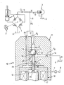
- a vehicle power steering system comprising, in a manner known per se, a distribution servo valve 1 - actuated by the steering wheel 2 of a vehicle and interposed between a source of pressurized fluid 3, generally equipped with an integrated flow control device, and a cover 4 for selectively and alternately supplying pressurized fluid to the opposite chambers of a hydraulic assistance motor 5.
- the device 10 comprises a body 11 in which is formed a fluid passage consisting of an inlet passage 12 intended to be connected to the section of the bypass duct 6 coming from the outlet of the source 3, a passage enlarged intermediate 13 and an outlet passage 14 intended to be connected to the cover 4.
- the junction between the inlet passage 12 and the intermediate passage 1 3 forms a seat 14 of cross section S for a valve element 15 typically consisting of 'a ball.
- an electromagnetic control member 16 of the constant-gap electromagnet type the coil 17 of which receives the above-mentioned electric control signal 7 for controlling a plunger 18 capable of moving in a chamber 19 formed in the body 11 and communicating permanently, by a passage 20 in the body, with the entry of the entry passage 12.
- the chamber 19 is separated from the intermediate passage 13 by a partition 21, forming the bottom of the intermediate passage 13 opposite the valve seat 14.
- the partition 21 is traversed by a bore 22 coaxial with the inlet passage 12 and in which is sealed slidingly fitted a cylindrical plunger 23 of section s less than section S and having a first rounded end 24 cooperating, in chamber 19, with the plunger 18, and whose second end 25 cooperates, in the intermediate passage 13, with the valve element 15 to urge it towards its seat 14.
- the valve element 1 5 is also permanently urged against its seat 14 by a weakly calibrated spring 26.
- a fixed restriction ⁇ 1 is formed in the inlet passage 12, a fixed restriction ⁇ 2 being formed in the passage output 1 4.
- the force ⁇ is a function inversely proportional to the speed of the vehicle. provided by the sensor 8, which results in a decrease in the assistance provided by the hydraulic motor 5 when the vehicle speed increases.
- the force applied to the valve element 15 is close to the maximum value ⁇ M, the bypassed flow rate g then being almost zero.
Landscapes
- Engineering & Computer Science (AREA)
- Chemical & Material Sciences (AREA)
- Combustion & Propulsion (AREA)
- Transportation (AREA)
- Mechanical Engineering (AREA)
- Magnetically Actuated Valves (AREA)
- Power Steering Mechanism (AREA)
- Servomotors (AREA)
Applications Claiming Priority (2)
| Application Number | Priority Date | Filing Date | Title |
|---|---|---|---|
| FR8503688A FR2578920B1 (fr) | 1985-03-13 | 1985-03-13 | Dispositif asservi de controle de debit pour installation hydraulique, notamment pour direction assistee de vehicule |
| FR8503688 | 1985-03-13 |
Publications (2)
| Publication Number | Publication Date |
|---|---|
| EP0194929A1 true EP0194929A1 (de) | 1986-09-17 |
| EP0194929B1 EP0194929B1 (de) | 1988-01-20 |
Family
ID=9317150
Family Applications (1)
| Application Number | Title | Priority Date | Filing Date |
|---|---|---|---|
| EP86400460A Expired EP0194929B1 (de) | 1985-03-13 | 1986-03-05 | Drucksteuer-Servoeinrichtung für hydraulische Anlage, insbesondere für Kraftfahrzeugservolenkung |
Country Status (6)
| Country | Link |
|---|---|
| US (1) | US4672885A (de) |
| EP (1) | EP0194929B1 (de) |
| JP (1) | JPS61215170A (de) |
| DE (1) | DE3660018D1 (de) |
| ES (1) | ES8706908A1 (de) |
| FR (1) | FR2578920B1 (de) |
Cited By (2)
| Publication number | Priority date | Publication date | Assignee | Title |
|---|---|---|---|---|
| EP0414448A1 (de) * | 1989-08-19 | 1991-02-27 | Adwest Engineering Limited | Servolenkvorrichtung |
| EP0378311A3 (de) * | 1989-01-07 | 1991-04-10 | Burmans Limited | Steuerventil |
Families Citing this family (17)
| Publication number | Priority date | Publication date | Assignee | Title |
|---|---|---|---|---|
| US4861407A (en) * | 1985-06-18 | 1989-08-29 | The Dow Chemical Company | Method for adhesive bonding articles via pretreatment with energy beams |
| JPH0624949B2 (ja) * | 1986-04-10 | 1994-04-06 | 日産自動車株式会社 | 全油圧式パワ−ステアリング装置 |
| US4877099A (en) * | 1986-09-02 | 1989-10-31 | Ford Motor Company | Electronically controlled variable assist power steering system |
| US4760892A (en) * | 1986-09-02 | 1988-08-02 | Ford Motor Company | Variable assist power steering system using electronic pressure control |
| JPH0657533B2 (ja) * | 1986-09-30 | 1994-08-03 | 日産自動車株式会社 | パワ−ステアリングの油圧制御装置 |
| JP2543511B2 (ja) * | 1986-12-27 | 1996-10-16 | 日産自動車株式会社 | パワ−ステアリングの油圧制御装置 |
| JPH0815866B2 (ja) * | 1986-12-27 | 1996-02-21 | 日産自動車株式会社 | パワ−ステアリングの油圧制御装置 |
| JPS63166657A (ja) * | 1986-12-27 | 1988-07-09 | Nissan Motor Co Ltd | パワ−ステアリングの油圧制御装置 |
| JPS63166658A (ja) * | 1986-12-27 | 1988-07-09 | Nissan Motor Co Ltd | パワ−ステアリングの油圧制御装置 |
| JP2503218B2 (ja) * | 1986-12-27 | 1996-06-05 | 日産自動車株式会社 | パワ−ステアリングの油圧制御装置 |
| JP2532079B2 (ja) * | 1987-01-30 | 1996-09-11 | 日産自動車株式会社 | パワ−ステアリング用ロ−タリ制御弁 |
| JP2532081B2 (ja) * | 1987-01-30 | 1996-09-11 | 日産自動車株式会社 | パワ−ステアリングの油圧制御装置 |
| US4846296A (en) * | 1987-01-30 | 1989-07-11 | Nissan Motor Co., Ltd. | Hydraulic fluid pressure control system for use with power assist steering |
| JP2529679B2 (ja) * | 1987-01-30 | 1996-08-28 | 日産自動車株式会社 | パワ−ステアリングの油圧制御装置 |
| JPH0818571B2 (ja) * | 1987-06-29 | 1996-02-28 | 日産自動車株式会社 | パワ−ステアリングの油圧制御装置 |
| US5346175A (en) * | 1992-12-31 | 1994-09-13 | Kelsey-Hayes Company | Variable assist steering control valve |
| US5549361A (en) * | 1995-06-02 | 1996-08-27 | Kelsey-Hayes Corporation | Electronic-hydraulic brake boost using a power steering supply |
Citations (4)
| Publication number | Priority date | Publication date | Assignee | Title |
|---|---|---|---|---|
| FR2207481A5 (de) * | 1972-11-15 | 1974-06-14 | Nissan Motor | |
| FR2275715A1 (fr) * | 1974-06-20 | 1976-01-16 | Oswald Herve | Electrovanne a commande assistee interne |
| EP0071909A2 (de) * | 1981-08-05 | 1983-02-16 | Nissan Motor Co., Ltd. | Servolenkungseinrichtung für Fahrzeuge |
| EP0089512A2 (de) * | 1982-03-18 | 1983-09-28 | Nissan Motor Co., Ltd. | Fahrzeugservolenkung mit Lenkkraftkontrollsystem |
Family Cites Families (5)
| Publication number | Priority date | Publication date | Assignee | Title |
|---|---|---|---|---|
| US3744515A (en) * | 1972-06-29 | 1973-07-10 | Nissan Motor | Hydraulic pressure control valve for power-assisted steering system |
| US4609331A (en) * | 1982-04-16 | 1986-09-02 | Ford Motor Company | Speed sensitive power steering valve |
| US4457390A (en) * | 1982-06-16 | 1984-07-03 | Tokai Trw & Co. Ltd. | Power steering device |
| US4570735A (en) * | 1982-09-30 | 1986-02-18 | Ford Motor Company | Dual rotary valve for variable assist power steering gear for automotive vehicles |
| US4485883A (en) * | 1982-09-30 | 1984-12-04 | Ford Motor Company | Power steering system with vehicle speed-sensitive flow |
-
1985
- 1985-03-13 FR FR8503688A patent/FR2578920B1/fr not_active Expired
-
1986
- 1986-03-05 DE DE8686400460T patent/DE3660018D1/de not_active Expired
- 1986-03-05 EP EP86400460A patent/EP0194929B1/de not_active Expired
- 1986-03-11 US US06/838,746 patent/US4672885A/en not_active Expired - Lifetime
- 1986-03-13 JP JP61053854A patent/JPS61215170A/ja active Pending
- 1986-03-13 ES ES552969A patent/ES8706908A1/es not_active Expired
Patent Citations (4)
| Publication number | Priority date | Publication date | Assignee | Title |
|---|---|---|---|---|
| FR2207481A5 (de) * | 1972-11-15 | 1974-06-14 | Nissan Motor | |
| FR2275715A1 (fr) * | 1974-06-20 | 1976-01-16 | Oswald Herve | Electrovanne a commande assistee interne |
| EP0071909A2 (de) * | 1981-08-05 | 1983-02-16 | Nissan Motor Co., Ltd. | Servolenkungseinrichtung für Fahrzeuge |
| EP0089512A2 (de) * | 1982-03-18 | 1983-09-28 | Nissan Motor Co., Ltd. | Fahrzeugservolenkung mit Lenkkraftkontrollsystem |
Cited By (2)
| Publication number | Priority date | Publication date | Assignee | Title |
|---|---|---|---|---|
| EP0378311A3 (de) * | 1989-01-07 | 1991-04-10 | Burmans Limited | Steuerventil |
| EP0414448A1 (de) * | 1989-08-19 | 1991-02-27 | Adwest Engineering Limited | Servolenkvorrichtung |
Also Published As
| Publication number | Publication date |
|---|---|
| FR2578920B1 (fr) | 1987-05-29 |
| JPS61215170A (ja) | 1986-09-24 |
| US4672885A (en) | 1987-06-16 |
| FR2578920A1 (fr) | 1986-09-19 |
| ES8706908A1 (es) | 1987-06-16 |
| DE3660018D1 (en) | 1988-02-25 |
| ES552969A0 (es) | 1987-06-16 |
| EP0194929B1 (de) | 1988-01-20 |
Similar Documents
| Publication | Publication Date | Title |
|---|---|---|
| EP0194929B1 (de) | Drucksteuer-Servoeinrichtung für hydraulische Anlage, insbesondere für Kraftfahrzeugservolenkung | |
| EP1634787B1 (de) | Kraftfahrzeugbremsvorrichtung | |
| FR2525979A1 (fr) | Regulateur de glissement d'entrainement pour vehicule automobile | |
| EP0194927B1 (de) | Drucksteuer-Servoeinrichtung für hydraulische Anlage, insbesondere für Kraftfahrzeugservolenkung | |
| FR2507144A1 (fr) | Direction assistee, notamment pour vehicules utilitaires | |
| EP0194928B1 (de) | Drucksteuer-Servoeinrichtung für hydraulische Anlage, insbesondere für Kraftfahrzeugservolenkung | |
| FR2648097A1 (fr) | Maitre-cylindre, notamment pour systeme de freinage hydraulique antiblocage | |
| WO1993009484A1 (fr) | Dispositif de regulation de pression pour circuit hydraulique | |
| EP0072732B1 (de) | Durchflussregler für eine Servolenkungseinrichtung | |
| FR2813926A1 (fr) | Dispositif hydraulique a soupapes | |
| FR2563172A1 (fr) | Dispositif de direction de vehicules, commutable selectivement entre un mode de direction manuelle et un mode de guidage transversal automatique | |
| EP0401061A1 (de) | Modulator und Servolenkungskreis mit einem solchen Modulator | |
| EP0202154B1 (de) | Durchlaufkontroll-Servovorrichtung für hydraulische Einrichtung, insbesondere für Kraftfahrzeug-Servolenkung | |
| FR2516170A1 (fr) | Ensemble de pompes pour l'injection de combustible | |
| KR890000859B1 (ko) | 파워 스티어링 장치 | |
| FR2498723A1 (fr) | Soupape avec un embout de raccordement a la pression et un embout de raccordement a l'appareil de mesure | |
| EP0500407B1 (de) | Gasdruckregelungsverfahren und -Vorrichtung und eine solche Vorrichtung einschliessendes Gasfördersystem | |
| FR2483557A1 (fr) | Clapet a retard pour pression differentielle de faible valeur | |
| US4220218A (en) | Vehicle road speed control system with flow amplifier | |
| GB0317449D0 (en) | Valve | |
| FR2579549A1 (fr) | Systeme de direction assistee pour vehicule automobile | |
| EP0236197B1 (de) | Druckservoregler | |
| FR2596466A1 (fr) | Dispositif d'assistance hydraulique | |
| EP0396433B1 (de) | Fluidsteuervorrichtung und ein diese umfassender Servolenkungskreis | |
| EP0467723B1 (de) | Flüssigkeitsverteiler mit zweifacher Fluid-Steuerung |
Legal Events
| Date | Code | Title | Description |
|---|---|---|---|
| PUAI | Public reference made under article 153(3) epc to a published international application that has entered the european phase |
Free format text: ORIGINAL CODE: 0009012 |
|
| 17P | Request for examination filed |
Effective date: 19860320 |
|
| AK | Designated contracting states |
Kind code of ref document: A1 Designated state(s): DE GB IT |
|
| 17Q | First examination report despatched |
Effective date: 19870701 |
|
| ITF | It: translation for a ep patent filed | ||
| GRAA | (expected) grant |
Free format text: ORIGINAL CODE: 0009210 |
|
| AK | Designated contracting states |
Kind code of ref document: B1 Designated state(s): DE GB IT |
|
| GBT | Gb: translation of ep patent filed (gb section 77(6)(a)/1977) | ||
| REF | Corresponds to: |
Ref document number: 3660018 Country of ref document: DE Date of ref document: 19880225 |
|
| PLBE | No opposition filed within time limit |
Free format text: ORIGINAL CODE: 0009261 |
|
| STAA | Information on the status of an ep patent application or granted ep patent |
Free format text: STATUS: NO OPPOSITION FILED WITHIN TIME LIMIT |
|
| 26N | No opposition filed | ||
| ITTA | It: last paid annual fee | ||
| PGFP | Annual fee paid to national office [announced via postgrant information from national office to epo] |
Ref country code: GB Payment date: 19960226 Year of fee payment: 11 |
|
| PGFP | Annual fee paid to national office [announced via postgrant information from national office to epo] |
Ref country code: DE Payment date: 19960313 Year of fee payment: 11 |
|
| PG25 | Lapsed in a contracting state [announced via postgrant information from national office to epo] |
Ref country code: GB Effective date: 19970305 |
|
| GBPC | Gb: european patent ceased through non-payment of renewal fee |
Effective date: 19970305 |
|
| PG25 | Lapsed in a contracting state [announced via postgrant information from national office to epo] |
Ref country code: DE Effective date: 19971202 |
|
| PG25 | Lapsed in a contracting state [announced via postgrant information from national office to epo] |
Ref country code: IT Free format text: LAPSE BECAUSE OF NON-PAYMENT OF DUE FEES;WARNING: LAPSES OF ITALIAN PATENTS WITH EFFECTIVE DATE BEFORE 2007 MAY HAVE OCCURRED AT ANY TIME BEFORE 2007. THE CORRECT EFFECTIVE DATE MAY BE DIFFERENT FROM THE ONE RECORDED. Effective date: 20050305 |