EP0195191A1 - Système avec marquage passif pour la conduite et la commande d'unités de transport et de montage sans conducteur - Google Patents
Système avec marquage passif pour la conduite et la commande d'unités de transport et de montage sans conducteur Download PDFInfo
- Publication number
- EP0195191A1 EP0195191A1 EP86100908A EP86100908A EP0195191A1 EP 0195191 A1 EP0195191 A1 EP 0195191A1 EP 86100908 A EP86100908 A EP 86100908A EP 86100908 A EP86100908 A EP 86100908A EP 0195191 A1 EP0195191 A1 EP 0195191A1
- Authority
- EP
- European Patent Office
- Prior art keywords
- passive
- track
- passive track
- vehicle
- bar code
- Prior art date
- Legal status (The legal status is an assumption and is not a legal conclusion. Google has not performed a legal analysis and makes no representation as to the accuracy of the status listed.)
- Granted
Links
- 238000005314 correlation function Methods 0.000 claims abstract description 13
- 239000002184 metal Substances 0.000 claims abstract 2
- 238000000034 method Methods 0.000 claims description 9
- 230000003287 optical effect Effects 0.000 claims description 5
- 230000001965 increasing effect Effects 0.000 claims description 3
- 230000008569 process Effects 0.000 claims description 3
- 238000005507 spraying Methods 0.000 claims description 3
- 230000010355 oscillation Effects 0.000 claims description 2
- 230000001680 brushing effect Effects 0.000 claims 1
- 239000013589 supplement Substances 0.000 claims 1
- 238000011156 evaluation Methods 0.000 abstract description 10
- 238000012545 processing Methods 0.000 abstract description 4
- 239000002985 plastic film Substances 0.000 abstract 1
- 229920006255 plastic film Polymers 0.000 abstract 1
- 238000005259 measurement Methods 0.000 description 10
- 230000001939 inductive effect Effects 0.000 description 5
- 230000008859 change Effects 0.000 description 3
- 238000013461 design Methods 0.000 description 3
- 238000003384 imaging method Methods 0.000 description 3
- 239000000463 material Substances 0.000 description 3
- 239000000243 solution Substances 0.000 description 3
- 210000002023 somite Anatomy 0.000 description 3
- 238000004026 adhesive bonding Methods 0.000 description 2
- 238000004364 calculation method Methods 0.000 description 2
- 238000012937 correction Methods 0.000 description 2
- 230000001419 dependent effect Effects 0.000 description 2
- 238000005516 engineering process Methods 0.000 description 2
- 238000012423 maintenance Methods 0.000 description 2
- 238000004519 manufacturing process Methods 0.000 description 2
- 238000012986 modification Methods 0.000 description 2
- 230000004048 modification Effects 0.000 description 2
- 238000010422 painting Methods 0.000 description 2
- 230000008439 repair process Effects 0.000 description 2
- 238000009420 retrofitting Methods 0.000 description 2
- 238000012546 transfer Methods 0.000 description 2
- 229910000859 α-Fe Inorganic materials 0.000 description 2
- 241001136792 Alle Species 0.000 description 1
- 238000012935 Averaging Methods 0.000 description 1
- 241001295925 Gegenes Species 0.000 description 1
- XAGFODPZIPBFFR-UHFFFAOYSA-N aluminium Chemical compound [Al] XAGFODPZIPBFFR-UHFFFAOYSA-N 0.000 description 1
- 229910052782 aluminium Inorganic materials 0.000 description 1
- 230000004888 barrier function Effects 0.000 description 1
- 230000005540 biological transmission Effects 0.000 description 1
- 238000004140 cleaning Methods 0.000 description 1
- 238000000205 computational method Methods 0.000 description 1
- 238000010276 construction Methods 0.000 description 1
- 230000007547 defect Effects 0.000 description 1
- 238000009795 derivation Methods 0.000 description 1
- 238000001514 detection method Methods 0.000 description 1
- 238000011161 development Methods 0.000 description 1
- 230000018109 developmental process Effects 0.000 description 1
- 230000000694 effects Effects 0.000 description 1
- 238000010292 electrical insulation Methods 0.000 description 1
- 230000036039 immunity Effects 0.000 description 1
- 230000006698 induction Effects 0.000 description 1
- 230000010354 integration Effects 0.000 description 1
- 238000012544 monitoring process Methods 0.000 description 1
- 238000010606 normalization Methods 0.000 description 1
- 230000005693 optoelectronics Effects 0.000 description 1
- 230000005855 radiation Effects 0.000 description 1
- 230000009467 reduction Effects 0.000 description 1
- 239000004065 semiconductor Substances 0.000 description 1
- 230000035945 sensitivity Effects 0.000 description 1
Images


Classifications
-
- G—PHYSICS
- G05—CONTROLLING; REGULATING
- G05D—SYSTEMS FOR CONTROLLING OR REGULATING NON-ELECTRIC VARIABLES
- G05D1/00—Control of position, course, altitude or attitude of land, water, air or space vehicles, e.g. using automatic pilots
- G05D1/02—Control of position or course in two dimensions
- G05D1/021—Control of position or course in two dimensions specially adapted to land vehicles
- G05D1/0231—Control of position or course in two dimensions specially adapted to land vehicles using optical position detecting means
- G05D1/0244—Control of position or course in two dimensions specially adapted to land vehicles using optical position detecting means using reflecting strips
-
- G—PHYSICS
- G05—CONTROLLING; REGULATING
- G05D—SYSTEMS FOR CONTROLLING OR REGULATING NON-ELECTRIC VARIABLES
- G05D1/00—Control of position, course, altitude or attitude of land, water, air or space vehicles, e.g. using automatic pilots
- G05D1/02—Control of position or course in two dimensions
- G05D1/021—Control of position or course in two dimensions specially adapted to land vehicles
- G05D1/0231—Control of position or course in two dimensions specially adapted to land vehicles using optical position detecting means
- G05D1/0234—Control of position or course in two dimensions specially adapted to land vehicles using optical position detecting means using optical markers or beacons
Definitions
- the present invention relates to a passive track system for guiding and controlling driverless transport and assembly units, in particular industrial trucks, comprising a passive track attached to the ground as a guideline with at least one feature different from the rest of the roadway, and a vehicle-supported scanning device for tracking the passive track.
- Such passive track systems are generally applicable when it comes to guiding mobile objects along a guideline and making optimal use of the flexibility of trackless conveyors, e.g. in the construction and operation of flexible manufacturing systems.
- the present invention is directed to a vehicle control system with a passive guideline, as described in DE-OS No. 29 49 204.
- This passive track guidance system works on the principle of brightness balance and uses a light band as a guideline, which is delimited on both sides by two contrasting dark bands. Light emitted by the vehicle is reflected on the three bands and received by two vehicle-based light sensors, each of which generates a signal that is proportional to the average brightness within the measurement window of the same size. If the first light sensor above the associated measurement window now delivers a larger signal than the second light sensor above its measurement window, the lateral tracking of the vehicle with respect to the light and the two dark bands is corrected so that both measurement windows have the same middle Have brightness and the brightness balance is thus restored.
- the sensitivity of the system is a function of the contrast, i.e. generally proportional to (R1-R2) / (R1 + R2) with R1, R2 equal to the reflection coefficients the light band or the two dark bands.
- R1-R2 the contrast
- R1 + R2 the reflection coefficients the light band or the two dark bands.
- the invention solves the problem of increasing the flexibility and simplifying the structure and function of an operating system for track-guided transport and assembly units.
- the innovation aims to design a guideline in such a way that it can be easily and quickly attached to the floor and also removed again and at the same time serves to guide and function control the vehicles.
- the new operating system is also said to be largely tolerant of soiling of the guideline and roadway, and to have increased immunity to interference and functional reliability.
- the innovation is fully compatible with conventional inductive tracking systems.
- Its reading device consisting of a reading head and evaluation electronics, corresponds functionally and largely in the interface to the vehicle control to the known ferrite antenna with subsequent signal processing in induction loops.
- the new passive track system is therefore ideally suited for retrofitting and retrofitting existing inductive tracking systems.
- the special optical reading device and the novel evaluation of the received signals based on statistical averaging are geared towards the operation of trackless vehicles, its use is economical and efficient, especially in flexible manufacturing systems.
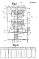
- Fig. 1 shows a possible embodiment of the passive track system, as is provided for guiding and controlling a vehicle FZ.
- the vehicle FZ consists of two separate driving cells connected with a load-bearing support body 3 and each with a joint 4, 4 ', which are constructed in a mirror-symmetrical manner and which are constructed identically and of which only one is shown in the present example and designated by 2.
- Each driving cell 2 essentially contains a steerable drive wheel R (not shown) with driving and steering servo, two trailing support wheels R S , R S 'and the necessary reading devices 13, 20 for scanning the passive track 9 and the bar code 28.
- the vehicle designed in this way FZ is completely symmetrical with regard to forward / reverse travel.
- the passive track 9 which can be permanently attached to the floor using simple methods such as painting, spraying or gluing and can also be easily removed for repair or modification, normally consists of a highly reflective plastic tape glued to the floor.
- the chosen plastic has sufficiently high contrast to a large number of floors of different qualities, has a high wear resistance and is resistant to common materials used in industry.
- a passive track 9 designed in this way can also be cleaned with cleaning machines.
- the passive track guidance system consists of the passive track 9 attached to the floor and the vehicle-supported passive track reading devices 13, 13 'for forward and backward travel with their reading heads 14, 14' and evaluation electronics 16, 16 '.
- As active optical elements of the read heads 14, 14 '8 each track sensors SS1, SS 2 ... SS 8 or 1 SS', SS 2 '...
- SL 1 , SL 2 ... SL 16 denote 16 lane positions, in the areas of which the roadway has a brightness value depending on whether the associated brightness measurement window is entirely in the passive lane 9 (SL 8 ; SL 9 ) or entirely in the floor areas 11, 12 (SL 1 to SL 6 ; SL 11 to SL 16 ) adjoining on both sides or half each in the passive track 9 and in the floor areas 11, 12 (SL 7 ; SL 10 ) adjoining on both sides.
- These brightness values represent a discrete brightness profile of the road running in the transverse direction, which serves as a "pattern".
- a possible lane deviation is determined by the vehicle by defining its current lane position, which is defined by light values measured by the track sensors SS 1 , SS 2 ... SS 8 or SS 1 ', SS 2 ' ... SS 8 ', with the "pattern".
- the passive track control system also includes the bar code 28, which is formed as part of the passive track 9, and the vehicle-based bar code reading device 20, comprising a reading head 21 with code sensors CS 1 , CS 2 ... CS 5 and evaluation electronics 24.
- FIG. 2a shows the passive lane guidance system in connection with two vehicles FZ and FZ ', which are centered with respect to the passive lane 9 or are shifted to the right by 1.25 lane positions on the carriageway.
- the passive track reading device 13 composed of the read head 14 and evaluation electronics 16 corresponds functionally and largely in the interface to the vehicle control to the known ferrite antenna for inductive loops with subsequent signal processing, so that optionally one or the other tracking system can be used.
- the position information transmitted to the computer of the vehicle control via parallel output 30 has the form of a digital value in the value range -127 to +128 for both systems.
- the reading device is largely insensitive to extraneous light such as workplace lighting by means of incandescent or gas discharge lamps, sunlight and IR radiation from various light barriers etc., which is also due to a certain shielding effect of the vehicle body, especially against the top, is achieved.
- the individual sensors are mounted linearly at a distance of 12.5 mm across the direction of travel.
- the active sensor area is 3.2x1.55 mm.
- Up to two reading heads can be connected to the evaluation electronics 16 via the cable 25.
- This contains a computer and an InterfacePrint 17 or 18 and is equipped to perform all the necessary functions.
- the computer print software contains all the necessary programs for calculating the lane deposit using the procedure for controlling examinations, such as the start of the lane, the end of the lane, and data transmission to the vehicle computer, which will be explained in detail later.
- the reading head 14 can be provided with a 90-degree beam deflection.
- LEDs or IR emitters 45 illuminate the roadway area located in the area of the reading head 14, the light reflected within the track brightness measurement window SF 1 , SF 2 ... SF 8 illuminating after deflection in a prism 38 integrated with an 8-fold collecting line 37 the active area of the track sensors SS 1 , SS 2 ... SS 8 is guided.
- simple optics with a 4: 1 imaging scale are installed.
- An active track brightness measurement window SF 1 , SF 2 ... SF 8 of 12.8x6.20 mm per track sensor is achieved.
- FIG. 3a shows the cross-correlation function curves 39, 40 as they correspond to the centered or decentered lane position of the two vehicles FZ and FZ 'in FIG. 2a.
- the grid dimension d used results in discrete functions consisting of the base values 41 which are assigned to the base points 1 to 9.
- the maxima 42 and 43 are important because their assigned support points, regardless of the brightness of the passive track 9 or the background, coincide with the lane positions of the vehicles FZ or FZ 'and thus indicate their lane deviation.
- the function maxima 42, 43 can fall on a base value or - which should occur far more frequently - take a position between the base values. In the latter case, the method shown in Fig. 3b is used.
- the discrete cross-correlation function is replaced by a continuously running curve 48, which results from quadratic interpolation from the support values 49, 50 and 51 in the support points M-1, M and M + 1.
- the absolute maximum value is then designated 52 and occupies the position M.
- the corresponding quality factor of the passive lane system is entered in a table for each possible assignment between 8 route sections and 5 vehicles, "1" for unusable, "255" for ideal condition.
- Those quality factors who calculated by the vehicles but always include the overall quality of the part of the passive lane system based on a vehicle FZ and the passive lane 9 in the assigned route section 36.
- the quality factors of the route sections are passed on by each individual vehicle higher-level stationary control device transmitted.
- the stationary computer which is also required when using processor-controlled vehicles for disposition, etc., maintains the table according to FIG. 4. It can be seen from this that there is no total defect. On the other hand, it emerges from a majority consideration that the passive lane 9 in the route section No. 2 is dirty or worn at one or more points and that the vehicle No. 4 and possibly also the vehicle No. 5 should be checked.
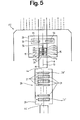
- the passive track system as a passive track control system, consisting of the bar code 28 attached to the floor and the bar code reading device 20 installed in the vehicle FZ.
- the bar code 28 basically consists of transverse breaks 27 in the guideline and is therefore an integral part of the passive track 9.
- the bar code 28 can be permanently affixed to the floor by processes such as painting, spraying or gluing and can also be removed for repair or modification.
- the bar code 28 In the illustrated in Fig. 5
- the bar code 28 consists of a glued-on, low-reflection plastic strip 29 which serves as a contrast-enhancing background and on which the highly reflective code strips 31 are applied.
- the code strips 31 differ by two different lengths as logic “0” and logic “1", so that in the present exemplary embodiment they have the following dimensions: 53 x 5 mm for logic "0", 53 x 11.5 mm for logic "1".
- the distance between the individual code strips 31 is uniformly 8 mm.
- Striking interruptions 44, 44 ', both ⁇ 43.5 mm, are provided at the beginning and at the end of the code sequence for initializing or ending the code reading.
- Another variant for bar code 28 is to attach a thin aluminum sheet to the floor, which is anodized black / white in the pattern of the code.
- the bar code reading device 20 installed in the vehicle FZ for reading the bar code 28 consists of a reading head 21 and evaluation electronics 24 and is integrated in the passive track reading device 13, 13 'or is constructed separately when the passive track control system is used alone.
- the code sensors CS 1 , CS 2 ... CS 5 with an active sensor area of 1 x 1 mm are arranged one behind the other in the direction of travel at a distance of 1.5 mm.
- By a Optics with a 2: 1 imaging scale achieve an active code area of 2x2 mm.
- a semiconductor light source 15, 15 ' is installed on each side of the code sensors CS 1 , CS 2 ... CS 5 .
- a maximum of two reading heads 21 can be connected to the evaluation electronics 24 via a connecting cable 54 each. This contains a computer print 55 and an interface print 56 and is equipped to perform all functions that are part of the normal operating sequence.
- FIG. 6 The integration of the read heads 14 and 21 for the passive track 9 and the bar code 28 made possible by using a uniform technology is shown in FIG. 6.
- the track sensors SS 1 ... SS 8 and the code sensors CS 1 ... CS 5 with their imaging optics 63 and 64 and lighting diodes 45 and 15 are combined on a print 61 in the housing 62 to form an optics block 65 which is controlled by electronics 66 and the connector 67 is connected to the vehicle computer 17.
- This embodiment variant of the invention dispenses with the right-angled beam deflection in the case of the track sensors SS 1 ... SS 8 and also uses only a light source for illuminating the associated track brightness measurement window SF 1 ... SF 8 .
- the 8 track sensors SS 1 , SS 2 ... SS 8 are of fundamental importance for the function as a passive track guidance system according to FIGS. 2a and 2b. They "observe" the road and inform the vehicle FZ of the road section over which it is currently located by supplying electrical signals f 1 , f 2 ... f 8 which are proportional to the average brightness within the track brightness measurement window SF 1 ... SF 8 are in the relevant lane area and are referred to as ACTUAL values. Since the track positions SL 1 , SL 2 ... SL 16 on the carriageway 26 and the track sensors SS 1 , SS 2 ...
- This TARGET value set is stored in the computer 17 and represents a normalized brightness profile of the roadway, which extends on both sides of the passive lane center line 10 in the transverse direction over 8 lane spacings each.
- the vehicle FZ determines which area of the TARGET brightness profile best matches the measured ACTUAL brightness profile. The central position of this area then corresponds to the lane position of the vehicle FZ.
- the best correspondence between the two brightness profiles is calculated by cross-correlation of the ACTUAL value set with the TARGET value set.
- the cross correlation be defined as follows: with the mean of the n actual measured values f . and provided that the average of the 2n SET values s . is zero
- the cross-correlation function ⁇ fs ( ⁇ ) between n sensor values and 2n tracking values is available in the form of n + 1 support values.
- the cross-correlation functions ⁇ fs ( ⁇ ) and ⁇ ' fs ( ⁇ ) shown in FIG. 3a result from the above-mentioned value sets for f, f n 'and s n .
- these are discrete or pseudo-continuous functions.
- the track positions of the vehicles FZ, FZ ' are given by the maxima of the associated cross-correlation functions ⁇ fs ( ⁇ ) and ⁇ ' fs ( ⁇ ). It the next step is to specify a simple computational method for determining the maximum of the cross-correlation function ⁇ fs ( ⁇ ).
- the result m is the interpolated location of the maximum of the cross-correlation function in relation to the location M of the maximum base value, which completes the 3rd step.
- Equipped vehicles For the function as a passive lane control system according to FIG. 5, information is required at certain points in the route network so that the vehicle (FC) performs a certain function at the right point, such as stopping, branching, transferring the load, reducing speed, etc.
- processors Equipped vehicles require additional information, such as place or route names, transfer location numbers, etc., in order to ensure operation that is as autonomous as possible and independent of fixed facilities.
- This information which usually consists of several bits - a data word - and for which the greatest possible spatial accuracy is required, is encoded in the bar code (28). This is read by the code sensors CS ... CS 5 while driving or at a standstill and the information obtained in this way is sent to the vehicle control system.
- the number of thin (logical "0") and thick (logical "1") contained in bar code 28 is Code strip 31 limited.
- 1 to 16 useful bits and up to 5 additional correction or redundancy bits are used per data word. The number of useful bits is determined depending on the application and remains constant within a system.
- Barcode reading is carried out by the 3 consecutively arranged code sensors CS 1 , CS 2 and CS 4 and is also possible with the vehicle at a standstill or with pendulum movements above the code.
- 3 code reading sensors By using 3 code reading sensors, an oscillation on the code strip 31 with amplitudes up to 5 mm is recognized and multiple evaluations of the same code strip 31 are excluded.
- Code reading is initialized with code sensors CS 3 and CS 5 . Because no strobe signal is required, the read head 21 with the code sensors CS 1 ... CS 5 can be guided obliquely over the bar code 28 to +/- 30 °.
- a code strip 31 for logic “0” is recognized in that the code sensors CS 1 , CS 2 and CS 4 change to the “sensor one” state in a combination that is dependent on the reading direction, depending on the previous state.
- a code strip 31 for logic “1” is recognized in that the code sensors CS 1 , CS 2 and CS 4 change to the "sensor one" state regardless of the previous state.
- the start or end of the code is generated by a distinctive interruption 44, 44 'of the reflective material, which means that all sensors, ie Change code reading and initialization sensors to the "sensor zero” state.
- the distance between the code strips 31 is selected such that none of the above states for logic "0", logic "1" and the beginning or end of the code can occur. At least one of the 3 code reading sensors CS 1 , CS 2 , CS 4 is always in the "sensor one” state.
- the passive track 9 is used twice, namely by the track sensors SS 1 ... SS 8 . as a guideline and from the code sensors CS 1 ... CS 5 as a source of information. Bar code 28, together with its actual function for function control, is also used for tracking at the same time. Although the reflective code strips 31 have a lower average brightness value than the regular passive track 9, their contrast is sufficient for tracking.
Landscapes
- Engineering & Computer Science (AREA)
- Physics & Mathematics (AREA)
- General Physics & Mathematics (AREA)
- Aviation & Aerospace Engineering (AREA)
- Radar, Positioning & Navigation (AREA)
- Remote Sensing (AREA)
- Electromagnetism (AREA)
- Automation & Control Theory (AREA)
- Control Of Position, Course, Altitude, Or Attitude Of Moving Bodies (AREA)
- Measuring Volume Flow (AREA)
- Ultra Sonic Daignosis Equipment (AREA)
- Vending Machines For Individual Products (AREA)
- Refuse Collection And Transfer (AREA)
Priority Applications (1)
| Application Number | Priority Date | Filing Date | Title |
|---|---|---|---|
| AT86100908T ATE48482T1 (de) | 1985-03-15 | 1986-01-23 | Passivspur-system zur fuehrung und steuerung von fahrerlosen transport- und montageeinheiten. |
Applications Claiming Priority (2)
| Application Number | Priority Date | Filing Date | Title |
|---|---|---|---|
| CH1173/85A CH668655A5 (de) | 1985-03-15 | 1985-03-15 | Passivspur-einrichtung zur fuehrung und steuerung von fahrerlosen transport- und montageeinheiten. |
| CH1173/85 | 1985-03-15 |
Publications (2)
| Publication Number | Publication Date |
|---|---|
| EP0195191A1 true EP0195191A1 (fr) | 1986-09-24 |
| EP0195191B1 EP0195191B1 (fr) | 1989-12-06 |
Family
ID=4204204
Family Applications (1)
| Application Number | Title | Priority Date | Filing Date |
|---|---|---|---|
| EP86100908A Expired EP0195191B1 (fr) | 1985-03-15 | 1986-01-23 | Système avec marquage passif pour la conduite et la commande d'unités de transport et de montage sans conducteur |
Country Status (9)
| Country | Link |
|---|---|
| US (1) | US4777601A (fr) |
| EP (1) | EP0195191B1 (fr) |
| JP (1) | JPS61213905A (fr) |
| AT (1) | ATE48482T1 (fr) |
| CA (1) | CA1264490A (fr) |
| CH (1) | CH668655A5 (fr) |
| DE (1) | DE3667343D1 (fr) |
| ES (1) | ES8701392A1 (fr) |
| FI (1) | FI88344C (fr) |
Cited By (12)
| Publication number | Priority date | Publication date | Assignee | Title |
|---|---|---|---|---|
| EP0290634A1 (fr) * | 1987-05-09 | 1988-11-17 | Carl Schenck Ag | Méthode de guidage d'un véhicule déplaçable à volonté sans pilote |
| EP0374294A1 (fr) * | 1988-12-22 | 1990-06-27 | Siemens Aktiengesellschaft | Dispositif de transmission d'information à un véhicule à voie de guidage |
| EP0383352A1 (fr) * | 1989-02-16 | 1990-08-22 | Maschinenfabrik Rieter Ag | Capteur pour la conduite automatique de véhicules |
| EP0661614A3 (fr) * | 1993-12-30 | 1995-09-13 | Honda Motor Co Ltd | Système de détection de la position d'un robot mobile et de contrÔle de celui-ci. |
| FR2762085A1 (fr) * | 1997-04-09 | 1998-10-16 | Cilas | Procede pour determiner la position d'un capteur par rapport a une bande longitudinale, capteur pour mettre en oeuvre ledit procede et application |
| EP0949495A1 (fr) * | 1998-04-02 | 1999-10-13 | Volkswagen Aktiengesellschaft | Dispositif et procédé pour la simulation d'un accident de véhicule |
| EP2704882A4 (fr) * | 2011-05-04 | 2014-10-15 | Harvest Automation Inc | Robot adaptable de manipulation de récipients avec sous-système de détection de limites |
| US8915692B2 (en) | 2008-02-21 | 2014-12-23 | Harvest Automation, Inc. | Adaptable container handling system |
| US8937410B2 (en) | 2012-01-17 | 2015-01-20 | Harvest Automation, Inc. | Emergency stop method and system for autonomous mobile robots |
| US9147173B2 (en) | 2011-10-31 | 2015-09-29 | Harvest Automation, Inc. | Methods and systems for automated transportation of items between variable endpoints |
| DE102020200894A1 (de) | 2020-01-27 | 2021-07-29 | Zf Friedrichshafen Ag | Codierung von Informationen in Fahrbahnmarkierungen |
| EP4592786A1 (fr) * | 2024-01-25 | 2025-07-30 | Marusys Co., Ltd. | Robot de traçage de ligne et procédé de commande de robot de traçage de ligne |
Families Citing this family (55)
| Publication number | Priority date | Publication date | Assignee | Title |
|---|---|---|---|---|
| FR2610427B1 (fr) * | 1987-02-04 | 1995-09-29 | Protee | Systeme et procede de controle de la marche d'un vehicule autonome |
| US5002145A (en) * | 1988-01-29 | 1991-03-26 | Nec Corporation | Method and apparatus for controlling automated guided vehicle |
| JPH07120194B2 (ja) * | 1988-03-31 | 1995-12-20 | 株式会社椿本チエイン | 無人搬送車の走行制御方法及びその装置 |
| US4942531A (en) * | 1988-05-16 | 1990-07-17 | Bell & Howell Company | Self-adapting signal detector with digital outputs |
| US4990841A (en) * | 1989-09-19 | 1991-02-05 | Apogee Robotics | Magnetically guided vehicle |
| US5111401A (en) * | 1990-05-19 | 1992-05-05 | The United States Of America As Represented By The Secretary Of The Navy | Navigational control system for an autonomous vehicle |
| US5191528A (en) * | 1990-06-28 | 1993-03-02 | Eaton-Kenway, Inc. | Update marker system for naviagtion of an automatic guided vehicle |
| US5216605A (en) * | 1990-06-28 | 1993-06-01 | Eaton-Kenway, Inc. | Update marker system for navigation of an automatic guided vehicle |
| US5281901A (en) * | 1990-12-03 | 1994-01-25 | Eaton-Kenway, Inc. | Downward compatible AGV system and methods |
| US5187664A (en) * | 1990-11-27 | 1993-02-16 | Eaton-Kenway, Inc. | Proportional position-sensing system for an automatic guided vehicle |
| CA2053028C (fr) * | 1990-10-23 | 1996-04-09 | Hideichi Tanizawa | Systeme de controle de la circulation de chariots |
| US5127486A (en) * | 1990-11-23 | 1992-07-07 | Eaton-Kenway, Inc. | System for sensing arrival of an automatic guided vehicle at a wire |
| US5175415A (en) * | 1990-11-27 | 1992-12-29 | Eaton-Kenway, Inc. | Combination drive-wheel mechanism and travel-sensor mechanism |
| US5539646A (en) * | 1993-10-26 | 1996-07-23 | Hk Systems Inc. | Method and apparatus for an AGV inertial table having an angular rate sensor and a voltage controlled oscillator |
| US5961571A (en) * | 1994-12-27 | 1999-10-05 | Siemens Corporated Research, Inc | Method and apparatus for automatically tracking the location of vehicles |
| US5991674A (en) * | 1996-05-02 | 1999-11-23 | Chrysler Corporation | Floor shifter linkage for robotic control of vehicle |
| US5865266A (en) * | 1996-05-02 | 1999-02-02 | Chrysler Corporation | Steering wheel linkage for robotic system for automated durability road (ADR) facility |
| US5913945A (en) * | 1996-05-02 | 1999-06-22 | Daimlerchrysler Corporation | Pedal linkage for robotic control of vehicle |
| US5821718A (en) * | 1996-05-07 | 1998-10-13 | Chrysler Corporation | Robotic system for automated durability road (ADR) facility |
| US5906647A (en) * | 1996-09-03 | 1999-05-25 | Chrysler Corporation | Vehicle mounted guidance antenna for automated durability road (ADR) facility |
| US6141620A (en) * | 1996-09-03 | 2000-10-31 | Chrysler Corporation | Vehicle control system for automated durability road (ADR) facility |
| US5867089A (en) * | 1996-09-03 | 1999-02-02 | Chrysler Corporation | Base-to-remotely controlled vehicle communications for automated durability road (ADR) facility |
| US5908454A (en) * | 1996-09-03 | 1999-06-01 | Chrysler Corporation | Operator interface for automated durability road (ADR) facility |
| US5938705A (en) * | 1996-09-03 | 1999-08-17 | Chrysler Corporation | Vehicle controller (VCON) for automated durability road (ADR) facility |
| US6061613A (en) * | 1996-09-03 | 2000-05-09 | Chrysler Corporation | Base station for automated durability road (ADR) facility |
| US6453237B1 (en) * | 1999-04-23 | 2002-09-17 | Global Locate, Inc. | Method and apparatus for locating and providing services to mobile devices |
| KR20010044053A (ko) * | 2000-06-23 | 2001-06-05 | 유재춘 | 이동 로봇의 주행 상태 감지 장치 |
| GB2374797A (en) * | 2001-04-23 | 2002-10-30 | Paolo Niccolai | Self propelled and guided household or other indoor appliance |
| JP2002321699A (ja) * | 2001-04-27 | 2002-11-05 | Mitsubishi Heavy Ind Ltd | 航空貨物搬送システム |
| NL1019191C2 (nl) * | 2001-10-18 | 2003-04-23 | Frog Navigation Systems B V | Voertuig en werkwijze voor het besturen daarvan. |
| ES2268122T3 (es) | 2001-12-12 | 2007-03-16 | Jervis B. Webb International Company | Sistema y procedimiento de guiado de vehiculos sin conductor. |
| GB2384691A (en) * | 2002-01-29 | 2003-08-06 | Paolo Niccolai | Self propelled and guided floor cleaner or transport device |
| BRPI0511407A (pt) * | 2004-05-03 | 2008-01-22 | Webb Int Co Jerwis B | sistema para carga automática de transporte utilizando o método de referência cruzada |
| US8192137B2 (en) | 2004-05-03 | 2012-06-05 | Jervis B. Webb Company | Automatic transport loading system and method |
| US7980808B2 (en) * | 2004-05-03 | 2011-07-19 | Jervis B. Webb Company | Automatic transport loading system and method |
| US8210791B2 (en) * | 2004-05-03 | 2012-07-03 | Jervis B. Webb Company | Automatic transport loading system and method |
| US8075243B2 (en) | 2004-05-03 | 2011-12-13 | Jervis B. Webb Company | Automatic transport loading system and method |
| DE102005024881A1 (de) * | 2005-05-31 | 2006-12-07 | Still Gmbh | Flurförderzeug mit einer elektrischen Steuerungseinheit |
| US20060276958A1 (en) * | 2005-06-02 | 2006-12-07 | Jervis B. Webb Company | Inertial navigational guidance system for a driverless vehicle utilizing laser obstacle sensors |
| US8768558B2 (en) * | 2007-01-05 | 2014-07-01 | Agjunction Llc | Optical tracking vehicle control system and method |
| USRE48527E1 (en) * | 2007-01-05 | 2021-04-20 | Agjunction Llc | Optical tracking vehicle control system and method |
| US9702707B2 (en) * | 2011-12-22 | 2017-07-11 | AppLabz, LLC | Systems, methods, and apparatus for providing indoor navigation using optical floor sensors |
| WO2013116654A1 (fr) * | 2012-02-03 | 2013-08-08 | Siemens Healthcare Diagnostice, Inc. | Système de codage incorporé dans une surface de piste d'automatisation |
| CN104679004B (zh) * | 2015-02-09 | 2017-07-11 | 上海交通大学 | 柔性路径与固定路径相结合的自动导引车及其导引方法 |
| US10589931B2 (en) | 2016-09-30 | 2020-03-17 | Staples, Inc. | Hybrid modular storage fetching system |
| US10683171B2 (en) | 2016-09-30 | 2020-06-16 | Staples, Inc. | Hybrid modular storage fetching system |
| EP3519937A4 (fr) | 2016-09-30 | 2020-04-29 | Staples, Inc. | Système de récupération de stockage modulaire hybride |
| EP3399379B1 (fr) * | 2017-05-05 | 2023-04-26 | Leuze electronic GmbH + Co. KG | Système de détection |
| US11590997B1 (en) | 2018-08-07 | 2023-02-28 | Staples, Inc. | Autonomous shopping cart |
| US11084410B1 (en) | 2018-08-07 | 2021-08-10 | Staples, Inc. | Automated guided vehicle for transporting shelving units |
| US11630447B1 (en) | 2018-08-10 | 2023-04-18 | Staples, Inc. | Automated guided vehicle for transporting objects |
| US11119487B2 (en) | 2018-12-31 | 2021-09-14 | Staples, Inc. | Automated preparation of deliveries in delivery vehicles using automated guided vehicles |
| US11180069B2 (en) | 2018-12-31 | 2021-11-23 | Staples, Inc. | Automated loading of delivery vehicles using automated guided vehicles |
| US11124401B1 (en) | 2019-03-31 | 2021-09-21 | Staples, Inc. | Automated loading of delivery vehicles |
| US11221631B2 (en) * | 2019-04-24 | 2022-01-11 | Innovation First, Inc. | Performance arena for robots with position location system |
Citations (4)
| Publication number | Priority date | Publication date | Assignee | Title |
|---|---|---|---|---|
| DE2459358A1 (de) * | 1973-12-17 | 1975-06-19 | Hitachi Ltd | Vorrichtung zur erfassung einer reflektierenden substanz auf einem traegerkoerper |
| US4139862A (en) * | 1977-09-08 | 1979-02-13 | Nasa | Interactive color display for multispectral imagery using correlation clustering |
| FR2406245A1 (fr) * | 1977-10-13 | 1979-05-11 | Matra Engins | Installation de transport a guidage automatique |
| EP0012554A1 (fr) * | 1978-12-06 | 1980-06-25 | BELL & HOWELL COMPANY | Système de guidage pour véhicule comportant une tête de balayage |
Family Cites Families (13)
| Publication number | Priority date | Publication date | Assignee | Title |
|---|---|---|---|---|
| US3738443A (en) * | 1969-11-28 | 1973-06-12 | M Kubo | Control system for the travel of a goods trolley |
| JPS49110020A (fr) * | 1973-02-21 | 1974-10-19 | ||
| US3935922A (en) * | 1974-07-16 | 1976-02-03 | Lear Siegler, Inc. | Vehicle guidance mechanism |
| US4020918A (en) * | 1975-12-31 | 1977-05-03 | Lear Siegler, Inc. | Manually operable automatically controlled vehicle with power steering |
| US4003445A (en) * | 1976-02-12 | 1977-01-18 | Lear Siegler, Inc. | Code circuitry for a vehicle guidance mechanism |
| US4278142A (en) * | 1978-05-08 | 1981-07-14 | Agency Of Industrial Science And Technology | Automatic guidance system for vehicles |
| FR2443713A1 (fr) * | 1978-12-06 | 1980-07-04 | Matra | Installation a vehicules automatiques |
| JPS5911922B2 (ja) * | 1980-08-13 | 1984-03-19 | 株式会社日立製作所 | 無人搬送装置 |
| SE423839B (sv) * | 1980-10-02 | 1982-06-07 | Volvo Ab | Sett och anordning for styrning av ett styrbart hjulfordon |
| SE423840B (sv) * | 1980-10-02 | 1982-06-07 | Volvo Ab | Sett att vid ett med dod rekning styrt hjulfordon anordna en uppdatering |
| JPS59112312A (ja) * | 1982-12-20 | 1984-06-28 | Nippon Yusoki Co Ltd | 無人搬送車の誘導帯 |
| JPS6063618A (ja) * | 1983-09-17 | 1985-04-12 | Tsubakimoto Chain Co | 無人走行車の走行制御方法 |
| JPS61204713A (ja) * | 1985-03-07 | 1986-09-10 | Murata Mach Ltd | 無人走行車の誘導方式 |
-
1985
- 1985-03-15 CH CH1173/85A patent/CH668655A5/de not_active IP Right Cessation
-
1986
- 1986-01-23 ES ES551163A patent/ES8701392A1/es not_active Expired
- 1986-01-23 AT AT86100908T patent/ATE48482T1/de active
- 1986-01-23 DE DE8686100908T patent/DE3667343D1/de not_active Expired - Fee Related
- 1986-01-23 EP EP86100908A patent/EP0195191B1/fr not_active Expired
- 1986-02-27 CA CA000502828A patent/CA1264490A/fr not_active Expired - Fee Related
- 1986-03-03 US US06/835,248 patent/US4777601A/en not_active Expired - Fee Related
- 1986-03-06 FI FI860938A patent/FI88344C/fi not_active IP Right Cessation
- 1986-03-14 JP JP61056746A patent/JPS61213905A/ja active Pending
Patent Citations (4)
| Publication number | Priority date | Publication date | Assignee | Title |
|---|---|---|---|---|
| DE2459358A1 (de) * | 1973-12-17 | 1975-06-19 | Hitachi Ltd | Vorrichtung zur erfassung einer reflektierenden substanz auf einem traegerkoerper |
| US4139862A (en) * | 1977-09-08 | 1979-02-13 | Nasa | Interactive color display for multispectral imagery using correlation clustering |
| FR2406245A1 (fr) * | 1977-10-13 | 1979-05-11 | Matra Engins | Installation de transport a guidage automatique |
| EP0012554A1 (fr) * | 1978-12-06 | 1980-06-25 | BELL & HOWELL COMPANY | Système de guidage pour véhicule comportant une tête de balayage |
Non-Patent Citations (1)
| Title |
|---|
| PROCEEDINGS OF THE 4TH INTERNATIONAL SYMPOSIUM ON INDUSTRIAL ROBOTS, Tokyo, JP, 19. - 21. November 1974, Seiten 385-393, Japan Industrial Robot Association, Tokyo, JP; S. ANDO et al.: "Unattended travelling vehicle guided by optical means" * |
Cited By (17)
| Publication number | Priority date | Publication date | Assignee | Title |
|---|---|---|---|---|
| EP0290634A1 (fr) * | 1987-05-09 | 1988-11-17 | Carl Schenck Ag | Méthode de guidage d'un véhicule déplaçable à volonté sans pilote |
| EP0374294A1 (fr) * | 1988-12-22 | 1990-06-27 | Siemens Aktiengesellschaft | Dispositif de transmission d'information à un véhicule à voie de guidage |
| EP0383352A1 (fr) * | 1989-02-16 | 1990-08-22 | Maschinenfabrik Rieter Ag | Capteur pour la conduite automatique de véhicules |
| US5066854A (en) * | 1989-02-16 | 1991-11-19 | Rieter Machine Works Ltd. | Method of and apparatus for guiding a self-steering vehicle along an optical guideway |
| US5144130A (en) * | 1989-02-16 | 1992-09-01 | Rieter Machine Works Limited | Method for the electrical adjustment of an optical row of sensors |
| US6021363A (en) * | 1993-12-30 | 2000-02-01 | Honda Giken Kogyo Kabushiki Kaisha | System for detecting and controlling the position of a mobile robot |
| EP0661614A3 (fr) * | 1993-12-30 | 1995-09-13 | Honda Motor Co Ltd | Système de détection de la position d'un robot mobile et de contrÔle de celui-ci. |
| US5737217A (en) * | 1993-12-30 | 1998-04-07 | Honda Giken Kogyo Kabushiki Kaisha | System for detecting and controlling the position of a mobile robot |
| FR2762085A1 (fr) * | 1997-04-09 | 1998-10-16 | Cilas | Procede pour determiner la position d'un capteur par rapport a une bande longitudinale, capteur pour mettre en oeuvre ledit procede et application |
| EP0949495A1 (fr) * | 1998-04-02 | 1999-10-13 | Volkswagen Aktiengesellschaft | Dispositif et procédé pour la simulation d'un accident de véhicule |
| US8915692B2 (en) | 2008-02-21 | 2014-12-23 | Harvest Automation, Inc. | Adaptable container handling system |
| EP2704882A4 (fr) * | 2011-05-04 | 2014-10-15 | Harvest Automation Inc | Robot adaptable de manipulation de récipients avec sous-système de détection de limites |
| US9147173B2 (en) | 2011-10-31 | 2015-09-29 | Harvest Automation, Inc. | Methods and systems for automated transportation of items between variable endpoints |
| US9568917B2 (en) | 2011-10-31 | 2017-02-14 | Harvest Automation, Inc. | Methods and systems for automated transportation of items between variable endpoints |
| US8937410B2 (en) | 2012-01-17 | 2015-01-20 | Harvest Automation, Inc. | Emergency stop method and system for autonomous mobile robots |
| DE102020200894A1 (de) | 2020-01-27 | 2021-07-29 | Zf Friedrichshafen Ag | Codierung von Informationen in Fahrbahnmarkierungen |
| EP4592786A1 (fr) * | 2024-01-25 | 2025-07-30 | Marusys Co., Ltd. | Robot de traçage de ligne et procédé de commande de robot de traçage de ligne |
Also Published As
| Publication number | Publication date |
|---|---|
| ES8701392A1 (es) | 1986-11-16 |
| FI88344B (fi) | 1993-01-15 |
| FI860938A0 (fi) | 1986-03-06 |
| JPS61213905A (ja) | 1986-09-22 |
| FI860938A7 (fi) | 1986-09-16 |
| CA1264490A (fr) | 1990-01-16 |
| DE3667343D1 (de) | 1990-01-11 |
| US4777601A (en) | 1988-10-11 |
| FI88344C (fi) | 1993-04-26 |
| ES551163A0 (es) | 1986-11-16 |
| ATE48482T1 (de) | 1989-12-15 |
| EP0195191B1 (fr) | 1989-12-06 |
| CH668655A5 (de) | 1989-01-13 |
Similar Documents
| Publication | Publication Date | Title |
|---|---|---|
| EP0195191B1 (fr) | Système avec marquage passif pour la conduite et la commande d'unités de transport et de montage sans conducteur | |
| DE3787003T2 (de) | Lenkvorrichtung für sich unbemannt bewegende körper. | |
| DE3889474T2 (de) | Navigationssystem und Verfahren zum Betrieb eines autonomen Fahrzeuges. | |
| EP0954773B1 (fr) | Procede et dispositif pour la mise a poste d'une unite mobile autonome | |
| DE3433555C2 (fr) | ||
| DE4013168C2 (de) | Fahrsteuerverfahren und Fahrsteuereinrichtung für ein Mobilrobotersystem | |
| EP0388390B1 (fr) | Système de mesure incrémentiel | |
| WO2000010062A2 (fr) | Procede et dispositif pour la determination d'une course autour d'une position de reference predeterminee | |
| DE2949204A1 (de) | Anlage mit automatisch gesteuerten fahrzeugen | |
| CH683703A5 (de) | Verfahren zur Geleisevermessung. | |
| DE102007029299B4 (de) | Optischer Sensor für Positionieraufgaben | |
| DE3715025A1 (de) | Fahrsteueranlage fuer transportwagen | |
| EP0058302A2 (fr) | Capteur de position pas à pas utilisant des techniques électro-optiques | |
| WO1986003612A1 (fr) | Dispositif d'ecartement de vehicules tenus sur une voie | |
| DE2557535B2 (de) | Fernerkennungsanordnung für Objekte | |
| EP1286181A1 (fr) | Conduisant des vehicules | |
| DE1413643B2 (de) | Verfahren zur selbsttaetigen durchfuehrung von arbeitspro grammen mit hilfe eines fahrzeuges | |
| DE3122970A1 (de) | Lenkeinrichtung zur steuerung der lenkung eines unbemannten fahrzeuges | |
| DE102010021042A1 (de) | Verfahren zur rechnergestützten Spurführung von Fahrzeugen | |
| DE3512127A1 (de) | Ortungs- und navigationssystem fuer landfahrzeuge | |
| DE2838583A1 (de) | Messystem zum messen der laenge von in bewegung befindlichen fahrzeugen | |
| EP0374290A1 (fr) | Véhicule ferroviaire | |
| DE3828447C2 (de) | Optische Leitvorrichtung für fahrerlose Transportsysteme | |
| DE102019116892A1 (de) | Fahrspurereignisantizipation durch LiDAR-Straßenbegrenzungserfassung | |
| DE3930109C1 (fr) |
Legal Events
| Date | Code | Title | Description |
|---|---|---|---|
| PUAI | Public reference made under article 153(3) epc to a published international application that has entered the european phase |
Free format text: ORIGINAL CODE: 0009012 |
|
| AK | Designated contracting states |
Kind code of ref document: A1 Designated state(s): AT BE CH DE FR GB IT LI NL SE |
|
| RAP1 | Party data changed (applicant data changed or rights of an application transferred) |
Owner name: JD-TECHNOLOGIE AG |
|
| 17P | Request for examination filed |
Effective date: 19870304 |
|
| ITCL | It: translation for ep claims filed |
Representative=s name: FUMERO BREVETTI S.N.C. |
|
| EL | Fr: translation of claims filed | ||
| 17Q | First examination report despatched |
Effective date: 19880711 |
|
| GRAA | (expected) grant |
Free format text: ORIGINAL CODE: 0009210 |
|
| ITF | It: translation for a ep patent filed | ||
| AK | Designated contracting states |
Kind code of ref document: B1 Designated state(s): AT BE CH DE FR GB IT LI NL SE |
|
| PG25 | Lapsed in a contracting state [announced via postgrant information from national office to epo] |
Ref country code: NL Effective date: 19891206 Ref country code: BE Effective date: 19891206 |
|
| REF | Corresponds to: |
Ref document number: 48482 Country of ref document: AT Date of ref document: 19891215 Kind code of ref document: T |
|
| ET | Fr: translation filed | ||
| REF | Corresponds to: |
Ref document number: 3667343 Country of ref document: DE Date of ref document: 19900111 |
|
| GBT | Gb: translation of ep patent filed (gb section 77(6)(a)/1977) | ||
| NLV1 | Nl: lapsed or annulled due to failure to fulfill the requirements of art. 29p and 29m of the patents act | ||
| PLBE | No opposition filed within time limit |
Free format text: ORIGINAL CODE: 0009261 |
|
| STAA | Information on the status of an ep patent application or granted ep patent |
Free format text: STATUS: NO OPPOSITION FILED WITHIN TIME LIMIT |
|
| 26N | No opposition filed | ||
| REG | Reference to a national code |
Ref country code: CH Ref legal event code: PUE Owner name: DIGITRON AG |
|
| ITPR | It: changes in ownership of a european patent |
Owner name: CESSIONE;DIGITRON AG |
|
| REG | Reference to a national code |
Ref country code: GB Ref legal event code: 732 |
|
| REG | Reference to a national code |
Ref country code: FR Ref legal event code: TP |
|
| ITTA | It: last paid annual fee | ||
| REG | Reference to a national code |
Ref country code: CH Ref legal event code: PFA Free format text: DIGITRON AG |
|
| ITPR | It: changes in ownership of a european patent |
Owner name: FUSIONI;SPRECHER + SCHUH AUTOMATION |
|
| REG | Reference to a national code |
Ref country code: FR Ref legal event code: CA |
|
| REG | Reference to a national code |
Ref country code: GB Ref legal event code: 732E |
|
| EAL | Se: european patent in force in sweden |
Ref document number: 86100908.2 |
|
| PGFP | Annual fee paid to national office [announced via postgrant information from national office to epo] |
Ref country code: CH Payment date: 19951222 Year of fee payment: 11 |
|
| PGFP | Annual fee paid to national office [announced via postgrant information from national office to epo] |
Ref country code: SE Payment date: 19960115 Year of fee payment: 11 Ref country code: GB Payment date: 19960115 Year of fee payment: 11 |
|
| PGFP | Annual fee paid to national office [announced via postgrant information from national office to epo] |
Ref country code: FR Payment date: 19960131 Year of fee payment: 11 Ref country code: DE Payment date: 19960131 Year of fee payment: 11 Ref country code: AT Payment date: 19960131 Year of fee payment: 11 |
|
| PG25 | Lapsed in a contracting state [announced via postgrant information from national office to epo] |
Ref country code: GB Effective date: 19970123 Ref country code: AT Effective date: 19970123 |
|
| PG25 | Lapsed in a contracting state [announced via postgrant information from national office to epo] |
Ref country code: SE Effective date: 19970124 |
|
| PG25 | Lapsed in a contracting state [announced via postgrant information from national office to epo] |
Ref country code: LI Effective date: 19970131 Ref country code: CH Effective date: 19970131 |
|
| GBPC | Gb: european patent ceased through non-payment of renewal fee |
Effective date: 19970123 |
|
| REG | Reference to a national code |
Ref country code: CH Ref legal event code: PL |
|
| PG25 | Lapsed in a contracting state [announced via postgrant information from national office to epo] |
Ref country code: FR Effective date: 19970930 |
|
| PG25 | Lapsed in a contracting state [announced via postgrant information from national office to epo] |
Ref country code: DE Effective date: 19971001 |
|
| EUG | Se: european patent has lapsed |
Ref document number: 86100908.2 |
|
| REG | Reference to a national code |
Ref country code: FR Ref legal event code: ST |
|
| PG25 | Lapsed in a contracting state [announced via postgrant information from national office to epo] |
Ref country code: IT Free format text: LAPSE BECAUSE OF NON-PAYMENT OF DUE FEES;WARNING: LAPSES OF ITALIAN PATENTS WITH EFFECTIVE DATE BEFORE 2007 MAY HAVE OCCURRED AT ANY TIME BEFORE 2007. THE CORRECT EFFECTIVE DATE MAY BE DIFFERENT FROM THE ONE RECORDED. Effective date: 20050123 |