EP0195280A2 - Dispositif pour tendre et aligner un cliché flexible sur le cylindre porte-plaque d'une machine à imprimer rotative - Google Patents
Dispositif pour tendre et aligner un cliché flexible sur le cylindre porte-plaque d'une machine à imprimer rotative Download PDFInfo
- Publication number
- EP0195280A2 EP0195280A2 EP86102500A EP86102500A EP0195280A2 EP 0195280 A2 EP0195280 A2 EP 0195280A2 EP 86102500 A EP86102500 A EP 86102500A EP 86102500 A EP86102500 A EP 86102500A EP 0195280 A2 EP0195280 A2 EP 0195280A2
- Authority
- EP
- European Patent Office
- Prior art keywords
- clamping
- tensioning
- screws
- rail
- pressure plate
- Prior art date
- Legal status (The legal status is an assumption and is not a legal conclusion. Google has not performed a legal analysis and makes no representation as to the accuracy of the status listed.)
- Granted
Links
Images

Classifications
-
- B—PERFORMING OPERATIONS; TRANSPORTING
- B41—PRINTING; LINING MACHINES; TYPEWRITERS; STAMPS
- B41F—PRINTING MACHINES OR PRESSES
- B41F27/00—Devices for attaching printing elements or formes to supports
- B41F27/12—Devices for attaching printing elements or formes to supports for attaching flexible printing formes
- B41F27/1218—Devices for attaching printing elements or formes to supports for attaching flexible printing formes comprising printing plate tensioning devices
- B41F27/1225—Devices for attaching printing elements or formes to supports for attaching flexible printing formes comprising printing plate tensioning devices moving in the printing plate end substantially rectilinearly
- B41F27/1231—Devices for attaching printing elements or formes to supports for attaching flexible printing formes comprising printing plate tensioning devices moving in the printing plate end substantially rectilinearly by translatory motion substantially tangential to support surface
Definitions
- the invention relates to a device for clamping and aligning flexible printing plates according to the preamble of claim 1.
- Such devices are known (DE-GM 8435189) and are used to place the printing plate to be clamped onto the plate cylinder as precisely as possible in order to avoid a subsequent correction.
- the tensioning rail can be aligned in a certain position at the start of the pressure using adjusting screws.
- means can also be provided on the printing plate itself, which facilitate the precise alignment of the printing plate. If this does not succeed, the applied pressure plate must be corrected, which as a rule leads to plastic deformations due to the wrap friction. These deformations in turn result in registration errors that are difficult to correct.
- a further disadvantage of the previous clamping devices has been that the starting position is lost when the adjusting screws are turned, that the positional accuracy is impaired by the thread play in the adjusting screws and that the tensioning rail tilts in its guides on the cylinder body when the pressure plate is inserted, even if between compression springs are provided in the two tensioning rails. All of this leads to inaccuracies in the alignment of the printing plate before it is placed on it, and inevitably to inaccurate clamping. Now runs the clamped in the front tensioning rail Pressing the pressure plate into the machine under pressure between the plate and blanket cylinders pulls the pressure plate on the front clamping rail and this tilts backwards in the direction of the tensile force of the pressure plate into the opposite contact position.
- the object is achieved with the characterizing features of claim 1.
- the preload achieved using an additional force makes it possible to switch off the play in the adjusting means, the additional force being chosen so high that the one-sided installation of the clamping means does not change even when a new pressure plate is inserted.
- the leaf springs are designed and attached so that no bending moments but only tensile forces act on the tensioning rail.
- the additional set screws according to claim 3 allow a precise setting of the desired starting position. This means that the pressure plate can be re-tensioned at any time without losing the target position determined by the set screws. This target position of the clamping rail can be simply by loosening the clamping screws * always find again.
- the embodiment according to claim 2 has the advantage that the leaf springs arranged as close as possible to the pressure plate do not hinder the necessary tensioning of the same.
- the clamped pressure plate can be inserted into the machine so precisely that the possibly necessary register corrections take place in the elastic range of the pressure plate due to the precise alignment and position determination of the front tensioning rail.
- the printing unit shown in FIG. 1 contains in a known manner a plate cylinder 1, a blanket cylinder 2 and a printing cylinder 3, which are mounted on both sides in machine side frames 4.
- the plate cylinder 1 is assigned a dampening unit 5 and an inking unit 6, which are also mounted on both sides in the machine side frames 4.
- the plate cylinder 1 has a channel 7, which runs axially parallel, in which a front clamping rail 8 and a rear clamping rail 9 are arranged. For clamping and aligning a new pressure plate 10, this is inserted into the front clamping rail 8 approximately in the position shown, whereby it loads the front clamping rail 8 - at least with its own weight.
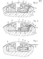
- FIG. 2 shows how the front end 11 of the pressure plate 10 is clamped between the clamping rail 8 and the cover rail 12 with the aid of a clamping rod 13.
- Such tensioning screws are also provided in the rear tensioning rail 9.
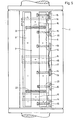
- Both clamping rails 8 and 9 are guided in the circumferential direction of the plate cylinder 1 in guides 16 which are fixed to the bottom of the channel 6.
- the front tensioning rail 8 is shown exaggeratedly tilted relative to the bottom of the channel 7 to show that when the pressure plate runs in between the plate cylinder 1 and the blanket cylinder 2 - which is done by rotating the two cylinders in the direction of the arrow - tensile forces act on the front end 11 of the pressure plate that lead to the shown tipping phenomenon in the context of the game.
- the pressure plate 10 corresponding to FIG. 1 is only inserted, which in the previously known designs led to the tilting movement in the opposite direction, as is exaggerated here.
- a leaf spring 17 is screwed on the front tensioning rail 8 in a manner that prevents it from rotating.
- the leaf spring 17 is provided directly under the pressure plate 10 and is suspended under prestress in stops 19 screwed onto the channel wall. It exerts a tensile force on the front clamping rail 8, so that it always remains in the tilt position shown in FIG. 3 even when a new pressure plate is inserted, as a result of which the play between the clamping rail 8 and the guide 16 and in the other clamping devices is excluded.
- two set screws 20 are provided, which are fixed via lock nuts 21. Via these adjusting screws 20, the tensioning rail 8 can be aligned in a specific starting position or setpoint position, so that this specific setpoint position can always be assumed after a clamping process.
- the set screws 20 are arranged at the same height as the clamping screws 14 in order to ensure the same tipping point of the clamping rail 8.
- the contact surfaces of the adjusting and clamping screws are spherical and are hereby supported on the stops 15 and 19. To compensate for any play can be provided between lock nut 21 and S p annschiene 8, a plate spring, not shown.
- compression springs 22 can be provided between the two tensioning rails 8 and 9 in order to prevent undesired displacement of the tensioning rail 9 in the guides 16. These compression springs also support the insertion of the rear end of the pressure plate 10 between the tensioning rail 9 and the cover rail 12.
- the pressure plate 10 can be with its front end 11 in the clamping rail 8, e.g. with the help of dowel bolts u. The like., Insert and align so precisely that a possibly necessary register fine correction takes place at the end of the pressure plate via the tensioning rail 9 in the elastic region of the pressure plate.
- the required stable starting position of the front clamping rail 8 is generated by the leaf springs 17.
- other types of springs can also be used instead of leaf springs.
Landscapes
- Supply, Installation And Extraction Of Printed Sheets Or Plates (AREA)
Applications Claiming Priority (2)
| Application Number | Priority Date | Filing Date | Title |
|---|---|---|---|
| DE3510440 | 1985-03-22 | ||
| DE19853510440 DE3510440A1 (de) | 1985-03-22 | 1985-03-22 | Vorrichtung zum einspannen und ausrichten von biegsamen druckplatten auf dem plattenzylinder von rotationsdruckmaschinen |
Publications (3)
| Publication Number | Publication Date |
|---|---|
| EP0195280A2 true EP0195280A2 (fr) | 1986-09-24 |
| EP0195280A3 EP0195280A3 (en) | 1987-06-16 |
| EP0195280B1 EP0195280B1 (fr) | 1990-04-25 |
Family
ID=6266055
Family Applications (1)
| Application Number | Title | Priority Date | Filing Date |
|---|---|---|---|
| EP86102500A Expired - Lifetime EP0195280B1 (fr) | 1985-03-22 | 1986-02-26 | Dispositif pour tendre et aligner un cliché flexible sur le cylindre porte-plaque d'une machine à imprimer rotative |
Country Status (4)
| Country | Link |
|---|---|
| US (1) | US4724762A (fr) |
| EP (1) | EP0195280B1 (fr) |
| JP (1) | JPS61220848A (fr) |
| DE (1) | DE3510440A1 (fr) |
Families Citing this family (14)
| Publication number | Priority date | Publication date | Assignee | Title |
|---|---|---|---|---|
| DE3519869A1 (de) * | 1985-06-03 | 1986-12-04 | Heidelberger Druckmaschinen Ag, 6900 Heidelberg | Spannschiene am plattenzylinder von rotationsdruckmaschinen |
| DE3806526A1 (de) * | 1988-03-01 | 1989-09-14 | Heidelberger Druckmasch Ag | Vorrichtung zum spannen von biegsamen druckplatten am plattenzylinder von rotationsdruckmaschinen |
| DE3933678A1 (de) * | 1989-10-09 | 1991-04-18 | Miller Johannisberg Druckmasch | Vorrichtung zum positionsgenauen spannen einer druckplatte auf einem druckzylinder |
| DE3936446A1 (de) * | 1989-11-02 | 1991-05-08 | Miller Johannisberg Druckmasch | Plattenzylinder einer druckmaschine |
| US5012738A (en) * | 1989-11-13 | 1991-05-07 | Hercules, Incorporated | Printing plate locking device |
| US5159877A (en) * | 1991-12-10 | 1992-11-03 | Ag-Bag Corporation | Rotor arrangement for a bagging machine |
| GR960100252A (el) * | 1996-07-17 | 1998-03-31 | Μπαρες τσιγκων εκτυπωτικων μηχανων οσφετ για την ταχεια και σωστη τοποθετηση του τσιγκου επι του κυλινδρου (καζανι). | |
| CZ297967B6 (cs) * | 2000-08-25 | 2007-05-09 | Heidelberger Druckmaschienen Ag | Zarízení na prestavování minimálne jednoho prvku registru v tiskovém stroji a zpusob k provádení takového prestavování |
| US6886312B1 (en) | 2003-11-07 | 2005-05-03 | Miller-St. Nazianz, Inc. | Compacting rotor for bagging machines |
| US8281716B2 (en) | 2008-12-24 | 2012-10-09 | Printing Research, Inc. | Anti-marking jackets comprised of fluoropolymer and methods of using in offset printing |
| US8578853B2 (en) * | 2008-12-24 | 2013-11-12 | Printing Research, Inc. | Anti-marking jackets comprised of attachment structure and methods of using in offset printing |
| US8424453B2 (en) * | 2010-09-01 | 2013-04-23 | Printing Research, Inc. | Apparatus and method for adjusting anti-marking jackets |
| US8677899B2 (en) | 2011-01-31 | 2014-03-25 | Printing Research, Inc. | Reversible anti-marking jackets and methods of using |
| US9346258B2 (en) | 2012-05-02 | 2016-05-24 | Printing Research, Inc. | Method for cleaning anti-marking jackets |
Family Cites Families (16)
| Publication number | Priority date | Publication date | Assignee | Title |
|---|---|---|---|---|
| DE8435189U1 (de) * | 1985-02-28 | Grapho Metronic Meß- und Regeltechnik GmbH & Co KG, 8000 München | Vorrichtung zum Einspannen und Justieren von Druckplatten auf den Plattenzylindern einer Druckmaschine | |
| US1765530A (en) * | 1927-10-22 | 1930-06-24 | Harris Seybold Potter Co | Plate clamp |
| GB448069A (en) * | 1935-08-19 | 1936-06-02 | Multigraph Co | Improvements in or relating to printing machines |
| DE946901C (de) * | 1942-11-26 | 1956-08-09 | Steinmesse & Stollberg K G | Schnellklemmvorrichtung fuer biegsame Druckplatten |
| US2641183A (en) * | 1948-07-24 | 1953-06-09 | Fairchild Camera Instr Co | Image-reproducing plate and cylinder assembly |
| US3168040A (en) * | 1962-07-18 | 1965-02-02 | Harris Intertype Corp | Plate clamp registering mechanism |
| US3557695A (en) * | 1967-07-29 | 1971-01-26 | Roland Offsetmaschf | Device for the fastening of a printing plate |
| DE2060001C3 (de) * | 1970-12-05 | 1975-08-28 | Koenig & Bauer Ag, 8700 Wuerzburg | Klemm- und Spannvorrichtung fur biegsame Druckplatten |
| US3884147A (en) * | 1972-05-26 | 1975-05-20 | Roland Offsetmaschf | Device for fastening flexible printing plates |
| US3858512A (en) * | 1973-03-22 | 1975-01-07 | Roland Offsetmaschf | Lock-up mechanism for flexible printing plates providing improved reference adjustment |
| DE2754080C3 (de) * | 1977-12-05 | 1982-01-07 | Registersystem für die Drucktechnik GmbH, 8000 München | Vorrichtung zum registerhaltigen Spannen von Druckplatten auf dem Plattenzylinder von Druckmaschinen |
| US4347788A (en) * | 1980-05-01 | 1982-09-07 | Harris Corporation | Plate lockup mechanism |
| JPS57205152A (en) * | 1981-06-13 | 1982-12-16 | Komori Printing Mach Co Ltd | Color register adjusting device for sheet printer |
| CH653616A5 (fr) * | 1983-07-26 | 1986-01-15 | De La Rue Giori Sa | Procede de fixation et d'ajustage d'une plaque d'impression sur un cylindre porte-plaques et dispositif de mise en oeuvre. |
| DE8412886U1 (de) * | 1984-04-26 | 1984-07-19 | Zimmerer, Alois, 8000 München | Offset-druckzylinder mit druckplatte |
| DE3505678A1 (de) * | 1985-02-19 | 1986-08-21 | Rolf Dr.-Ing. 8011 Neukeferloh Bosse | Einrichtesystem fuer offsetdruckmaschinen |
-
1985
- 1985-03-22 DE DE19853510440 patent/DE3510440A1/de active Granted
-
1986
- 1986-02-26 EP EP86102500A patent/EP0195280B1/fr not_active Expired - Lifetime
- 1986-03-20 JP JP61061018A patent/JPS61220848A/ja active Pending
-
1987
- 1987-03-27 US US07/032,986 patent/US4724762A/en not_active Expired - Fee Related
Also Published As
| Publication number | Publication date |
|---|---|
| EP0195280B1 (fr) | 1990-04-25 |
| DE3510440A1 (de) | 1986-09-25 |
| DE3510440C2 (fr) | 1992-04-16 |
| US4724762A (en) | 1988-02-16 |
| EP0195280A3 (en) | 1987-06-16 |
| JPS61220848A (ja) | 1986-10-01 |
Similar Documents
| Publication | Publication Date | Title |
|---|---|---|
| EP0238804B1 (fr) | Dispositif de fixation des clichés souples sur les cylindres de clichés dans les rotatives | |
| EP0195280B1 (fr) | Dispositif pour tendre et aligner un cliché flexible sur le cylindre porte-plaque d'une machine à imprimer rotative | |
| EP0425936A2 (fr) | Dispositif pour le repérage, la fixation et la tension rapides de plaques d'impression | |
| EP0201747B1 (fr) | Dispositif pour tendre parallèlement les clichés sur le cylindre à cliché d'une machine à imprimer | |
| EP0359959A2 (fr) | Dispositif d'encrage à lame | |
| EP0596337B1 (fr) | Dispositif pour placer en répérage des plaques d'impression sur des cylindres de plaque des machines | |
| EP1777072B1 (fr) | Méthode de fabrication d'une plaque d'impression | |
| DE3212414C2 (fr) | ||
| DE3936459C1 (fr) | ||
| EP1155838A2 (fr) | Cylindre porte-plaque et positionneur extérieur de plaque | |
| EP0429808B1 (fr) | Dispositif pour tendre avec un repérage exact une plaque d'impression sur un cylindre d'impression | |
| EP1592556A1 (fr) | Groupe d'impression pour machine d'impression | |
| DE2604874C3 (de) | Einrichtung zum Einpassen von Druckplatten für Offset-Rollen-Rotationsdruckmaschinen | |
| DE3806526C2 (fr) | ||
| DE2720673B2 (de) | Vorrichtung zum ungleichförmigen Spannen eines Gummituches in einer Offsetdruckmaschine | |
| EP1182036A1 (fr) | Dispositif pour réglage d'au moins un élément de repérage dans une machine d'impression et procédé correspondant | |
| DE3246938A1 (de) | Druckmaschine mir druckplattenzylinder, farbauftragwalze und gegendruckzylinder | |
| DE10013804B4 (de) | Verfahren und Vorrichtung zum Aufspannen eines Zylinderaufzuges auf einen Druckmaschinenzylinder | |
| DE2926765A1 (de) | Vorrichtung zur unterdrueckung von biegeschwingungen in rotations-offsetdruckmaschinen | |
| DE3603218A1 (de) | Einrichtung zum einstellen eines buchblocktransportsystems insbesondere fuer klebebindemaschinen | |
| DE4410385C2 (de) | Vorrichtung zum Befestigen von Druckplatten | |
| DE4240462C2 (de) | Vorrichtung zum registergenauen Aufspannen von Druckplatten auf dem Plattenzylinder von Druckmaschinen | |
| CH697131A5 (de) | Ausrichtvorrichtung für ein Druckwerk einer Druckmaschine. | |
| DE8816324U1 (de) | Vorrichtung zum Einspannen und Justieren von Druckplatten auf den Plattenzylindern einer Druckmaschine | |
| WO2008006584A1 (fr) | Dispositif de serrage doté de moyens de serrage à imbrication |
Legal Events
| Date | Code | Title | Description |
|---|---|---|---|
| PUAI | Public reference made under article 153(3) epc to a published international application that has entered the european phase |
Free format text: ORIGINAL CODE: 0009012 |
|
| 17P | Request for examination filed |
Effective date: 19860226 |
|
| AK | Designated contracting states |
Kind code of ref document: A2 Designated state(s): CH FR GB IT LI NL SE |
|
| PUAL | Search report despatched |
Free format text: ORIGINAL CODE: 0009013 |
|
| AK | Designated contracting states |
Kind code of ref document: A3 Designated state(s): CH FR GB IT LI NL SE |
|
| 17Q | First examination report despatched |
Effective date: 19890202 |
|
| GRAA | (expected) grant |
Free format text: ORIGINAL CODE: 0009210 |
|
| AK | Designated contracting states |
Kind code of ref document: B1 Designated state(s): CH FR GB IT LI NL SE |
|
| ITF | It: translation for a ep patent filed | ||
| ET | Fr: translation filed | ||
| GBT | Gb: translation of ep patent filed (gb section 77(6)(a)/1977) | ||
| PLBE | No opposition filed within time limit |
Free format text: ORIGINAL CODE: 0009261 |
|
| STAA | Information on the status of an ep patent application or granted ep patent |
Free format text: STATUS: NO OPPOSITION FILED WITHIN TIME LIMIT |
|
| ITTA | It: last paid annual fee | ||
| 26N | No opposition filed | ||
| PGFP | Annual fee paid to national office [announced via postgrant information from national office to epo] |
Ref country code: SE Payment date: 19920212 Year of fee payment: 7 |
|
| PGFP | Annual fee paid to national office [announced via postgrant information from national office to epo] |
Ref country code: NL Payment date: 19920229 Year of fee payment: 7 |
|
| PG25 | Lapsed in a contracting state [announced via postgrant information from national office to epo] |
Ref country code: SE Effective date: 19930227 |
|
| PG25 | Lapsed in a contracting state [announced via postgrant information from national office to epo] |
Ref country code: NL Effective date: 19930901 |
|
| NLV4 | Nl: lapsed or anulled due to non-payment of the annual fee | ||
| EUG | Se: european patent has lapsed |
Ref document number: 86102500.5 Effective date: 19930912 |
|
| PGFP | Annual fee paid to national office [announced via postgrant information from national office to epo] |
Ref country code: GB Payment date: 19970121 Year of fee payment: 12 |
|
| PGFP | Annual fee paid to national office [announced via postgrant information from national office to epo] |
Ref country code: FR Payment date: 19970214 Year of fee payment: 12 |
|
| PGFP | Annual fee paid to national office [announced via postgrant information from national office to epo] |
Ref country code: CH Payment date: 19970326 Year of fee payment: 12 |
|
| PG25 | Lapsed in a contracting state [announced via postgrant information from national office to epo] |
Ref country code: GB Free format text: LAPSE BECAUSE OF NON-PAYMENT OF DUE FEES Effective date: 19980226 |
|
| PG25 | Lapsed in a contracting state [announced via postgrant information from national office to epo] |
Ref country code: LI Free format text: LAPSE BECAUSE OF NON-PAYMENT OF DUE FEES Effective date: 19980228 Ref country code: FR Free format text: THE PATENT HAS BEEN ANNULLED BY A DECISION OF A NATIONAL AUTHORITY Effective date: 19980228 Ref country code: CH Free format text: LAPSE BECAUSE OF NON-PAYMENT OF DUE FEES Effective date: 19980228 |
|
| GBPC | Gb: european patent ceased through non-payment of renewal fee |
Effective date: 19980226 |
|
| REG | Reference to a national code |
Ref country code: CH Ref legal event code: PL |
|
| REG | Reference to a national code |
Ref country code: FR Ref legal event code: ST |
|
| PG25 | Lapsed in a contracting state [announced via postgrant information from national office to epo] |
Ref country code: IT Free format text: LAPSE BECAUSE OF NON-PAYMENT OF DUE FEES;WARNING: LAPSES OF ITALIAN PATENTS WITH EFFECTIVE DATE BEFORE 2007 MAY HAVE OCCURRED AT ANY TIME BEFORE 2007. THE CORRECT EFFECTIVE DATE MAY BE DIFFERENT FROM THE ONE RECORDED. Effective date: 20050226 |