EP0195376B1 - Convoyeur avec un porteur suspendu - Google Patents
Convoyeur avec un porteur suspendu Download PDFInfo
- Publication number
- EP0195376B1 EP0195376B1 EP86103436A EP86103436A EP0195376B1 EP 0195376 B1 EP0195376 B1 EP 0195376B1 EP 86103436 A EP86103436 A EP 86103436A EP 86103436 A EP86103436 A EP 86103436A EP 0195376 B1 EP0195376 B1 EP 0195376B1
- Authority
- EP
- European Patent Office
- Prior art keywords
- carrier
- conveyor apparatus
- suspension
- support surface
- pivot axis
- Prior art date
- Legal status (The legal status is an assumption and is not a legal conclusion. Google has not performed a legal analysis and makes no representation as to the accuracy of the status listed.)
- Expired
Links
- 239000000725 suspension Substances 0.000 title claims abstract description 19
- 239000000969 carrier Substances 0.000 claims abstract description 9
- 230000008878 coupling Effects 0.000 claims 1
- 238000010168 coupling process Methods 0.000 claims 1
- 238000005859 coupling reaction Methods 0.000 claims 1
- 239000000463 material Substances 0.000 abstract description 2
- 238000006073 displacement reaction Methods 0.000 description 2
- 238000005352 clarification Methods 0.000 description 1
- 238000000034 method Methods 0.000 description 1
- 239000004753 textile Substances 0.000 description 1
Images

Classifications
-
- B—PERFORMING OPERATIONS; TRANSPORTING
- B65—CONVEYING; PACKING; STORING; HANDLING THIN OR FILAMENTARY MATERIAL
- B65G—TRANSPORT OR STORAGE DEVICES, e.g. CONVEYORS FOR LOADING OR TIPPING, SHOP CONVEYOR SYSTEMS OR PNEUMATIC TUBE CONVEYORS
- B65G9/00—Apparatus for assisting manual handling having suspended load-carriers movable by hand or gravity
- B65G9/002—Load-carriers, rollers therefor
Definitions
- the invention relates to a conveyor device according to the preamble of claim 1.
- the rail-shaped carrier has a U-profile.
- the continuous crossbar forms the support surface.
- the swivel axes are arranged within the U-cross section and the hanging bar is attached to it with an eyelet bent at its end.
- a slit in the carrier support surface from the free end allows the pivoting of the hanging bar at least up to the vertical to the carrier support surface, i.e. in the carrying position. If the carrier is to be brought into a space-saving storage position, each hanging rod must be pivoted about 270 °, i.e. H. can be folded into the U-profile.
- the swiveling movement from one position to the other requires a lot of free movement space and, especially in an environment of sensitive suspended goods, great care for the movement, which is simple in itself.
- the open side of the U-profile is unsuitable for attachments, in particular hangers or the like, as a support surface.
- the brackets can fall off, uncomfortable for textiles or the like thereon, or, if quickly hung up in large numbers empty, can get tangled and delay the loading process.
- the long swivel path can therefore not be avoided by using the support bracket in reverse.
- the object of the invention is to provide a conveyor of the type described in the introduction, the carriers of which are quicker, easier and more versatile to handle.
- the main advantage of the short pivoting movement is that it takes place over the carrier surface, not in its extension, and can therefore also be carried out in a confined space.
- a hanging carrier can be gripped simultaneously on both hanging rods and these can be folded up approximately simultaneously after lifting without changing the handle. The same applies in reverse for the movement from rest to work position.
- conventional conveyor systems of the type mentioned the necessary ground clearance is not available for a pivoting movement of 270 °.
- An embodiment characterized by the feature of claim 2 makes it possible, above all, to place the hanging rods close to the support surface without the swivel bearings displaced upward being in the way.
- the hinged hanging bar is secured in the clamping groove against unintentional swinging open.
- the pivot axis is taken along with every movement of the hanging bar and thus the clamping groove is brought into a certain position.
- the detachable connection has the advantage that hanging rods can be used for different carriers and carriers with different hanging rods. This can relate to dimensions, in the case of beams also to the profile or the design of the support surface, and in the case of hanging rods also to the shape of the end of the attachment which is remote from the beam.
- claims 3 and 4 to 7 each address advantageous embodiments with regard to the connection between the hanging rod and the pivot axis. It is possible through the bayonet-type locking between the pivot axis and hanging rod to hold the latter in different positions. This includes the possibility of reducing the transport height of the carrier by locking the hanging bar at a distance from its two ends. This means that their entire length is not used. This in turn results in the possibility of hanging carriers according to the invention for short items to be hung and thus increasing the transport capacity.
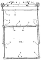
- FIG. 1 shows a section of a running rail 1 with a long trolley 2a supported thereon by means of roller sets 2.
- the running track 1 belonging to an entire system is fastened to the ceiling of a room by means of indicated broken brackets 3.
- An approximately rail-shaped support 6 is suspended from the long trolley 2a by means of hanging rods 4.
- One end of each hanging bar forms an open hook 5, which is adapted in shape and size to the cross section of the long trolley.
- Each hanging bar is on the support 6 attached to a pivot axis 7.
- the top of each rail-shaped carrier forms a carrier support surface 6a - see also FIG. 2 - for items not shown here, for example items of clothing on hangers.
- each pivot axis 7 is rotatably mounted between extensions of the side walls 6b and are offset upwards relative to the carrier support surface 6a. With each pivot axis 7, a hanging rod 4 is releasably securely connected, so that the pivot axis follows the pivoting movements of the hanging rod.
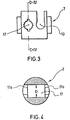
- the embodiment according to FIG. 1 shows a bayonet-like connection which will be discussed in more detail later with reference to FIGS. 3 and 4.
- each pivot axis 7 has a non-continuous threaded bore 8 and the hanging rod 4 has an external thread 9 at its end.
- a clamping groove 10 is provided on the pivot axis 7, into which the hanging rod attached to the opposite pivot axis 4 is clickable. It then lies close to the support surface 6a. Between the bearing area of the pivot axes 7 and the carrier support surface 6a, the side surfaces 6b each form rounded troughs 11, as shown in FIG. 1, the hooks 5 of further hanging rods 4 can be hooked into them.
- a pin 12 is attached projecting centrally upwards. It limits the sliding area for material to be conveyed suspended over the support surface.
- the underside 6c of the rail-shaped carrier is provided in the longitudinal direction with a toothed strip 13, the incisions 14 of which run between the teeth 15 transversely to the longitudinal direction of the carrier.
- each hanging bar 4 has at its lower end projections 16 which protrude on two sides.
- the pivot axis 7 has in addition to the Klenmnut 10 a continuous locking bore 17. Its inner diameter D corresponds to the greatest dimension 1 between the two ends of the projections 16. However, its entry and exit area 17a has an outline that is essentially the cross section of a hanging rod plus projections corresponds (Fig. 3).
- a carrier 6 hangs on the long trolley 2a by means of its hanging bars 4.
- Each hanging rod 4 of the upper support is locked in its pivot bearing 7 with projections 16 which are located approximately in the middle of their length, that is to say at a distance from their two ends. Your end region, which is also provided with projections 16, then projects freely downwards.
- the lower support 6 is hooked with the hooks 5 of its support rods 4 into the troughs 11 next to the pivot bearings of the upper support and its support rods 4 are fastened to the associated pivot bearings 7 with the projections 16 at their end remote from the hook.
- the projections 16 are matched in their extension to the longitudinal direction of the support rod to the deflection of the hook 5 so that when the projections are locked in the bore of the pivot bearing, the hook is in the correct position for hanging on the long trolley or another carrier.
- the locking of a support rod in a pivot bearing bore can also be achieved by other means.
- the support rod and bore can have an oval outline, so that a clamping fit is achieved by rotation.
- Notches on the profile of the support rod can also interact with corresponding locking points in the bore. Notches can be present in any number and even or changing intervals.
- FIG. 2 shows approximately the rest or storage position of a carrier.
- the support rods here attached to the respective pivot bearing by means of threads, are folded onto the support support surface 6a. This position is taken by the hanging bar lying behind from the viewer, while for clarification the hanging bar closer to the viewer still protrudes slightly inclined upwards.
- each support rod 4 engages in the clamping groove 10 of the opposite pivot axis and is thereby held on the carrier. In this position, the carrier requires little storage space. The pivoting movement of each support rod takes place in this way, i.e. directly towards the carrier.
- each support bar extends beyond the length of the carrier.
- the storage of each pivot axis makes it possible, if necessary, to hang the support upside down, with the toothed rack 13 upwards.
- Hangers or similar suspension elements can then each be distributed in the incisions 14 and thereby kept non-slip and at a distance. 1, 3 and 4, the holding rod can optionally also be used from the other side of the pivot axis bore.
- each carrier is largely arbitrary, and can even be circular, provided that a contact area is available for the folded hanging rods.
- the term "system" within the scope of the claims can include a small distance between the support surface and the hanging bar.
- the clamping groove 10 can also run all around on the pivot bearing or be arranged in the form of two incisions. It then offers the possibility of holding the second hanging bar even when the hanging bar attached to the pivot bearing is not in the folded position. This can e.g. B. be the case when a carrier should only be hung on a hanging bar, transported in a space-saving manner on the rail system or stored.
- the surface of the carrier can extend as a cover over the trough 11.
- the trough 11 can be dispensed with entirely if a different displacement limitation is provided for the conveyed goods or the hanging rods of another carrier or if a displacement up to the pivot bearing is accepted.
Landscapes
- Engineering & Computer Science (AREA)
- Mechanical Engineering (AREA)
- Chain Conveyers (AREA)
- Centrifugal Separators (AREA)
- Carriers, Traveling Bodies, And Overhead Traveling Cranes (AREA)
- Supplying Of Containers To The Packaging Station (AREA)
- Supports For Pipes And Cables (AREA)
Claims (11)
Priority Applications (1)
| Application Number | Priority Date | Filing Date | Title |
|---|---|---|---|
| AT86103436T ATE30566T1 (de) | 1985-03-19 | 1986-03-14 | Foerdereinrichtung mit haengetraeger. |
Applications Claiming Priority (2)
| Application Number | Priority Date | Filing Date | Title |
|---|---|---|---|
| DE19853509936 DE3509936A1 (de) | 1985-03-19 | 1985-03-19 | Foerdereinrichtung mit haengetraeger |
| DE3509936 | 1985-03-19 |
Publications (2)
| Publication Number | Publication Date |
|---|---|
| EP0195376A1 EP0195376A1 (fr) | 1986-09-24 |
| EP0195376B1 true EP0195376B1 (fr) | 1987-11-04 |
Family
ID=6265717
Family Applications (1)
| Application Number | Title | Priority Date | Filing Date |
|---|---|---|---|
| EP86103436A Expired EP0195376B1 (fr) | 1985-03-19 | 1986-03-14 | Convoyeur avec un porteur suspendu |
Country Status (7)
| Country | Link |
|---|---|
| US (1) | US4704969A (fr) |
| EP (1) | EP0195376B1 (fr) |
| AT (1) | ATE30566T1 (fr) |
| CA (1) | CA1316399C (fr) |
| CS (1) | CS268811B2 (fr) |
| DD (1) | DD243904A5 (fr) |
| DE (2) | DE3509936A1 (fr) |
Families Citing this family (6)
| Publication number | Priority date | Publication date | Assignee | Title |
|---|---|---|---|---|
| DE3901870A1 (de) * | 1989-01-23 | 1990-08-09 | Veit Transpo Gmbh | Haengefoerdersystem |
| US5076446A (en) * | 1989-06-14 | 1991-12-31 | Hanger-Tight Company | Hanger caddy transporter with restraining devices |
| US5067620A (en) * | 1990-09-17 | 1991-11-26 | Norrie Lyle W | Product support apparatus |
| US5501345A (en) * | 1993-11-15 | 1996-03-26 | Metro Industries, Inc. | Garment holder assembly |
| DE19721726C1 (de) * | 1997-05-24 | 1998-07-30 | Logotech Gmbh | Hängefördersystem |
| US20070017941A1 (en) * | 2005-07-20 | 2007-01-25 | Baessler Keith A | Garment hanger |
Family Cites Families (11)
| Publication number | Priority date | Publication date | Assignee | Title |
|---|---|---|---|---|
| US988468A (en) * | 1910-06-27 | 1911-04-04 | John H Harth | Seed-corn hanger. |
| US1738030A (en) * | 1928-11-02 | 1929-12-03 | Canton Stamping & Enameling Co | Burning rack |
| CH379076A (de) * | 1960-07-26 | 1964-06-30 | Moebelfabrik Horgen Glarus Ag | Umklappbares Möbelbein |
| US3179256A (en) * | 1964-02-10 | 1965-04-20 | Underwood Clem | Supporting bracket for multiple clothes hangers |
| US3441147A (en) * | 1967-08-28 | 1969-04-29 | Neal Kelley | Garment hanging device |
| US3473465A (en) * | 1968-04-22 | 1969-10-21 | Hormel & Co Geo A | Apparatus for pressing and smoking meat |
| US3696890A (en) * | 1970-05-05 | 1972-10-10 | Gilbert Armstrong | Article delivery system |
| ES401644A1 (es) * | 1972-01-12 | 1975-11-01 | Ralph Modellkleidung Ralph Lou | Un dispositivo de transporte, en especial para el transpor-te colgante interempresa en la industria del vestido. |
| US3827367A (en) * | 1972-11-27 | 1974-08-06 | M Paglia | Conveyor trolley with camming heads |
| US4162730A (en) * | 1977-04-18 | 1979-07-31 | Steere Marjorie S | Portable article hanger |
| DE7816030U1 (de) * | 1978-05-29 | 1978-10-26 | Fahmi, Ibrahim, 4150 Krefeld | Tragstab fuer mehrfachkleiderbuegel |
-
1985
- 1985-03-19 DE DE19853509936 patent/DE3509936A1/de not_active Withdrawn
-
1986
- 1986-02-21 US US06/832,156 patent/US4704969A/en not_active Expired - Lifetime
- 1986-03-13 CS CS861733A patent/CS268811B2/cs not_active IP Right Cessation
- 1986-03-14 DE DE8686103436T patent/DE3660007D1/de not_active Expired
- 1986-03-14 AT AT86103436T patent/ATE30566T1/de not_active IP Right Cessation
- 1986-03-14 EP EP86103436A patent/EP0195376B1/fr not_active Expired
- 1986-03-17 DD DD86287969A patent/DD243904A5/de unknown
- 1986-03-19 CA CA000504444A patent/CA1316399C/fr not_active Expired - Fee Related
Also Published As
| Publication number | Publication date |
|---|---|
| DD243904A5 (de) | 1987-03-18 |
| EP0195376A1 (fr) | 1986-09-24 |
| DE3660007D1 (en) | 1987-12-10 |
| CS173386A2 (en) | 1989-08-14 |
| DE3509936A1 (de) | 1986-09-25 |
| ATE30566T1 (de) | 1987-11-15 |
| US4704969A (en) | 1987-11-10 |
| CA1316399C (fr) | 1993-04-20 |
| CS268811B2 (en) | 1990-04-11 |
Similar Documents
| Publication | Publication Date | Title |
|---|---|---|
| DE3344659C1 (de) | Transportgestell fuer Haengefoerderung | |
| EP2125581B1 (fr) | Moyen de transport pour un dispositif de transport en suspension | |
| DE3906857C2 (de) | Transporteinrichtung mit L-förmigem Hänger | |
| EP3647238A1 (fr) | Dispositif de transport sous forme de convoyeur suspendu | |
| CH711921A1 (de) | Laufrollengeführtes Förderorgan und Förderanlage mit derartigen Förderorganen. | |
| EP1151941B1 (fr) | Etagère inclinée pour la préparation de commandes à partir des unités de stockage | |
| DE102022109936A1 (de) | Förderelement und Fördereinrichtung | |
| DE2310356A1 (de) | Foerdergestell | |
| DE1940256C3 (de) | Fördereinrichtung, insbesondere für die innerbetriebliche Hängeförderung in der Bekleidungsindustrie | |
| DE4319164C2 (de) | Förderer, insbesondere Stetigförderer für Einzelbügel | |
| EP0195376A1 (fr) | Convoyeur avec un porteur suspendu | |
| DE3221646C2 (fr) | ||
| DE9209392U1 (de) | Förderer | |
| EP1123881A2 (fr) | Dispositif de stockage, de manutention et de transport de pièces lors d'un traitement de surface | |
| DE4422772A1 (de) | Haltevorrichtung für Fahrräder | |
| CH658174A5 (de) | Warenpraesentiergestell. | |
| DE9406152U1 (de) | Vorrichtung zum Transport von Gegenständen | |
| EP0216950B1 (fr) | Porte-charge pour transporteur aérien | |
| DE8508205U1 (de) | Fördereinrichtung mit Hängeträger | |
| DE10355471B4 (de) | Regal- und Fördervorrichtung | |
| DE9002594U1 (de) | Hängefördereinrichtung | |
| DE102025108925B3 (de) | Anordnung zum multidirektionalen Transport von Stückgut | |
| DE8421274U1 (de) | Waeschehalter od. dgl. | |
| EP0682900A1 (fr) | Cintre pour vêtements | |
| EP3295104B1 (fr) | Dispositif de transfert et dispositif de transport de tiges pour des produits longs à base de pâte, procédé de fonctionnement d'un dispositif de transfert ou d'un dispositif de transport et séchoir à pâte |
Legal Events
| Date | Code | Title | Description |
|---|---|---|---|
| PUAI | Public reference made under article 153(3) epc to a published international application that has entered the european phase |
Free format text: ORIGINAL CODE: 0009012 |
|
| 17P | Request for examination filed |
Effective date: 19860724 |
|
| AK | Designated contracting states |
Kind code of ref document: A1 Designated state(s): AT BE CH DE FR GB LI LU NL |
|
| 17Q | First examination report despatched |
Effective date: 19870128 |
|
| GRAA | (expected) grant |
Free format text: ORIGINAL CODE: 0009210 |
|
| AK | Designated contracting states |
Kind code of ref document: B1 Designated state(s): AT BE CH DE FR GB LI LU NL |
|
| REF | Corresponds to: |
Ref document number: 30566 Country of ref document: AT Date of ref document: 19871115 Kind code of ref document: T |
|
| REF | Corresponds to: |
Ref document number: 3660007 Country of ref document: DE Date of ref document: 19871210 |
|
| ET | Fr: translation filed | ||
| GBT | Gb: translation of ep patent filed (gb section 77(6)(a)/1977) | ||
| PLBE | No opposition filed within time limit |
Free format text: ORIGINAL CODE: 0009261 |
|
| STAA | Information on the status of an ep patent application or granted ep patent |
Free format text: STATUS: NO OPPOSITION FILED WITHIN TIME LIMIT |
|
| 26N | No opposition filed | ||
| PGFP | Annual fee paid to national office [announced via postgrant information from national office to epo] |
Ref country code: LU Payment date: 19930312 Year of fee payment: 8 |
|
| EPTA | Lu: last paid annual fee | ||
| REG | Reference to a national code |
Ref country code: FR Ref legal event code: SN |
|
| PGFP | Annual fee paid to national office [announced via postgrant information from national office to epo] |
Ref country code: BE Payment date: 19940310 Year of fee payment: 9 |
|
| PG25 | Lapsed in a contracting state [announced via postgrant information from national office to epo] |
Ref country code: LU Free format text: LAPSE BECAUSE OF NON-PAYMENT OF DUE FEES Effective date: 19940314 |
|
| PGFP | Annual fee paid to national office [announced via postgrant information from national office to epo] |
Ref country code: NL Payment date: 19940331 Year of fee payment: 9 Ref country code: FR Payment date: 19940331 Year of fee payment: 9 |
|
| PGFP | Annual fee paid to national office [announced via postgrant information from national office to epo] |
Ref country code: CH Payment date: 19940511 Year of fee payment: 9 |
|
| PGFP | Annual fee paid to national office [announced via postgrant information from national office to epo] |
Ref country code: AT Payment date: 19950309 Year of fee payment: 10 |
|
| PG25 | Lapsed in a contracting state [announced via postgrant information from national office to epo] |
Ref country code: LI Effective date: 19950331 Ref country code: FR Free format text: THE PATENT HAS BEEN ANNULLED BY A DECISION OF A NATIONAL AUTHORITY Effective date: 19950331 Ref country code: CH Effective date: 19950331 Ref country code: BE Effective date: 19950331 |
|
| BERE | Be: lapsed |
Owner name: VEIT G.M.B.H. & CO. Effective date: 19950331 |
|
| PG25 | Lapsed in a contracting state [announced via postgrant information from national office to epo] |
Ref country code: NL Effective date: 19951001 |
|
| REG | Reference to a national code |
Ref country code: CH Ref legal event code: PL |
|
| NLV4 | Nl: lapsed or anulled due to non-payment of the annual fee |
Effective date: 19951001 |
|
| PG25 | Lapsed in a contracting state [announced via postgrant information from national office to epo] |
Ref country code: AT Effective date: 19960314 |
|
| REG | Reference to a national code |
Ref country code: FR Ref legal event code: ST |
|
| REG | Reference to a national code |
Ref country code: GB Ref legal event code: 732E |
|
| REG | Reference to a national code |
Ref country code: FR Ref legal event code: JE |
|
| REG | Reference to a national code |
Ref country code: FR Ref legal event code: RN |
|
| REG | Reference to a national code |
Ref country code: FR Ref legal event code: IC |
|
| REG | Reference to a national code |
Ref country code: GB Ref legal event code: IF02 |
|
| PGFP | Annual fee paid to national office [announced via postgrant information from national office to epo] |
Ref country code: GB Payment date: 20020311 Year of fee payment: 17 |
|
| PGFP | Annual fee paid to national office [announced via postgrant information from national office to epo] |
Ref country code: DE Payment date: 20020429 Year of fee payment: 17 |
|
| PG25 | Lapsed in a contracting state [announced via postgrant information from national office to epo] |
Ref country code: GB Free format text: LAPSE BECAUSE OF NON-PAYMENT OF DUE FEES Effective date: 20030314 |
|
| PG25 | Lapsed in a contracting state [announced via postgrant information from national office to epo] |
Ref country code: DE Free format text: LAPSE BECAUSE OF NON-PAYMENT OF DUE FEES Effective date: 20031001 |
|
| GBPC | Gb: european patent ceased through non-payment of renewal fee |
Effective date: 20030314 |