EP0195509B1 - Magnetron mit Anzeigevorrichtung für die augenblickliche Magnetronfrequenz - Google Patents
Magnetron mit Anzeigevorrichtung für die augenblickliche Magnetronfrequenz Download PDFInfo
- Publication number
- EP0195509B1 EP0195509B1 EP86300940A EP86300940A EP0195509B1 EP 0195509 B1 EP0195509 B1 EP 0195509B1 EP 86300940 A EP86300940 A EP 86300940A EP 86300940 A EP86300940 A EP 86300940A EP 0195509 B1 EP0195509 B1 EP 0195509B1
- Authority
- EP
- European Patent Office
- Prior art keywords
- magnetron
- frequency
- counter
- tuning member
- electrical pulses
- Prior art date
- Legal status (The legal status is an assumption and is not a legal conclusion. Google has not performed a legal analysis and makes no representation as to the accuracy of the status listed.)
- Expired
Links
- 230000003287 optical effect Effects 0.000 claims description 17
- 239000000835 fiber Substances 0.000 claims description 5
- 230000004044 response Effects 0.000 claims description 4
- 230000000694 effects Effects 0.000 description 2
- 238000000034 method Methods 0.000 description 2
- 230000005355 Hall effect Effects 0.000 description 1
- 239000011521 glass Substances 0.000 description 1
- 238000012544 monitoring process Methods 0.000 description 1
- 230000001360 synchronised effect Effects 0.000 description 1
- 230000001960 triggered effect Effects 0.000 description 1
Images


Classifications
-
- H—ELECTRICITY
- H01—ELECTRIC ELEMENTS
- H01J—ELECTRIC DISCHARGE TUBES OR DISCHARGE LAMPS
- H01J23/00—Details of transit-time tubes of the types covered by group H01J25/00
- H01J23/16—Circuit elements, having distributed capacitance and inductance, structurally associated with the tube and interacting with the discharge
- H01J23/18—Resonators
- H01J23/20—Cavity resonators; Adjustment or tuning thereof
Definitions
- the plates are divided into the same number of segments as there are anode cavities so that a variation in capacitance, resulting from rotation of the spinner, corresponds to the variation in magnetron frequency.
- a variation in capacitance resulting from rotation of the spinner
- the transducer suffers from the disadvantage that it is relatively bulky and is susceptible to interference from local fields within the magnetron.
- Hall effect devices responsive to a changing magnetic field caused by rotation of the spinner, as described in GB-A-1,077,680, have alternatively been used but again these tend to be susceptible to interference from local fields.
- a magnetron including a rotatable tuning member and a sensing arrangement responsive to rotation of the tuning member to provide an indication of the instantaneous magnetron frequency, characterised in that said sensing arrangement comprises a plurality of optical markings provided on the tuning member and spaced apart about the axis of rotation thereof,
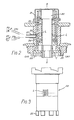
- Figure 2 illustrates a cross-sectional view through part of a coaxial magnetron and, as in the above-described example, the cathode shown at 20 is housed within a vacuum envelope 21.
- the magnetron has a tuning member in the form of a spinner 22 mounted by means of a pair of ball races 23, 24 for rotation about the longitudinal axis XX of the cathode.
- the spinner is coupled magnetically to a drive shaft mounted outside the envelope but not shown in Figure 2.
- the magnetron has 32, fixed anode vanes (not shown in the drawing) spaced evenly around the axis of the cathode.
- the spinner is provided with nine evenly spaced castellations C which are caused to rotate, in use, relative to an outer, fixed shutter 25 which also has nine, evenly spaced castellations located in the coaxial cavity of the magnetron shown generally at CAV.
- the spinner rotates and the castellations C on the spinner 22 move past the spaces between castellations on the shutter 25 the instantaneous magnetron frequency in the coaxial cavity changes.
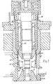
- the present invention is applicable to other forms of magnetrons having a rotatable tuning member, of the kind described in relation to Figure 1, for example.
- the spinner has a number of optical markings (L) located circumferentially on the exterior surface and an indication of the instantaneous magnetron frequency is derived by monitoring movement of the optical markings past a fixed reference position as the spinner rotates. This provides an indication of the angular position of the spinner and so the frequency excursion of the transmitted microwave energy.
- optical markings are shown, by way of example, on an exaggerated scale in the side view of the spinner illustrated in Figure 3.
- the optical markings comprise lines L formed by engraving the surface of the spinner although alternative arrangements are envisaged; the optical markings may be painted on the surface of the spinner, for example, and may comprise lines or dots.
- the spinner has, in effect, 72 lines spaced evenly at intervals of 0.5 mm around the circumference of the spinner; that is eight lines for every frequency cycle in the magnetron response.
- the first line in each group of eight, corresponding to the start of each new frequency cycle, is omitted.
- the magnetron is provided with a glass window shown at 26 in Figure 2 and light from a photo diode PD is directed through the window to illuminate the markings on the spinner within.
- Light is transmitted to the window along a fibre optic pipe FP, and light reflected at the spinner is transmitted along another fibre optic pipe FP 2 to a photo sensitive transistor PT which generates an electrical pulse in response to each change in light intensity as occasioned by movement of an engraving past the window.
- a common fibre optic cable (supplied for example by FORT Fibre Optics of Paris Ref. BFS) is used to transmit light to and away from the spinner, the cable being bonded into a mounting 27 in the vacuum envelope to abut the window 26.
- the optical markings are sensed by the photo sensitive transistor PT which generates a succession of square wave pulses. These are applied to an electrical circuit, shown in Figure 4, for processing to produce an output signal representing the variation in magnetron frequency.
- the pulses are received at an amplifier 41 and passed via a phase-locked loop 42 and a divide- by-32 network 43 to a binary counter 44 which counts pulses corresponding to each frequency cycle, i.e. up to 256 pulses (8 x 32).
- a counter reset circuit 45 is triggered, counter 44 is reset and the sequence repeated.
- Respective, predetermined frequency values, corresponding to the 256 pulses of each frequency cycle are stored in a memory 46, and a stored frequency value corresponding to the instantaneous value of the count is selected from memory 46 and routed, in digital form, to an output location O/P(1).
- an output signal generated, as described hereinbefore, has the same periodicity as the variation in magnetron frequency it would not provide an indication of the absolute position of the spinner.
- a synchronisation pulse is generated periodically at the start of each new frequency cycle. This pulse is decoded at 45 and used to reset the binary counter 44. In this way, the required frequency waveform, as illustrated in Figure 5, is generated in digital form at the output of the memory 46.
- An analogue output O/P(2) may be provided by a D/A converter 47 and amplifier 48. The digital or analogue output represents the changing magnetron frequency as the spinner rotates and is applied as a reference signal to the receiver local oscillator which is thereby synchronized with the transmitted magnetron frequency.
- the synchronisation pulses are generated, in this example, by provision of gap after successive groups of seven lines thus generating a discontinuity in the periodicity of pulses applied to amplifier 41 and marking the start of each frequency cycle.
Landscapes
- Microwave Tubes (AREA)
- Optical Transform (AREA)
Claims (7)
Applications Claiming Priority (2)
| Application Number | Priority Date | Filing Date | Title |
|---|---|---|---|
| GB8504219 | 1985-02-19 | ||
| GB8504219 | 1985-02-19 |
Publications (3)
| Publication Number | Publication Date |
|---|---|
| EP0195509A2 EP0195509A2 (de) | 1986-09-24 |
| EP0195509A3 EP0195509A3 (en) | 1988-01-07 |
| EP0195509B1 true EP0195509B1 (de) | 1991-01-16 |
Family
ID=10574706
Family Applications (1)
| Application Number | Title | Priority Date | Filing Date |
|---|---|---|---|
| EP86300940A Expired EP0195509B1 (de) | 1985-02-19 | 1986-02-12 | Magnetron mit Anzeigevorrichtung für die augenblickliche Magnetronfrequenz |
Country Status (3)
| Country | Link |
|---|---|
| US (1) | US4636750A (de) |
| EP (1) | EP0195509B1 (de) |
| DE (1) | DE3676842D1 (de) |
Families Citing this family (1)
| Publication number | Priority date | Publication date | Assignee | Title |
|---|---|---|---|---|
| US4881162A (en) * | 1988-03-15 | 1989-11-14 | Ltv Aerospace & Defense Co. | Frequency control system |
Family Cites Families (8)
| Publication number | Priority date | Publication date | Assignee | Title |
|---|---|---|---|---|
| US3440565A (en) * | 1966-03-17 | 1969-04-22 | Westinghouse Electric Corp | Sensor for detection of frequency of a reed modulated magnetron |
| US3811056A (en) * | 1971-12-06 | 1974-05-14 | Nissan Motor | Velocity sensor |
| IT1052772B (it) * | 1975-12-31 | 1981-07-20 | Olivetti C E C S P A | Dispositivo per rilevare la posizione angolare di un organo rotante..per esempio una testina di scrittura di una macchina per ufficio |
| GB1570191A (en) * | 1976-03-05 | 1980-06-25 | Ass Eng Ltd | Rotational speed transducers |
| GB1548038A (en) * | 1976-09-16 | 1979-07-04 | Emi Varian Ltd | Spin tuned magnetrons |
| US4387299A (en) * | 1979-06-25 | 1983-06-07 | Yazaki Sogyo Kabushiki Kaisha | Travel-distance signal generator for vehicles |
| DE3130965A1 (de) * | 1981-08-05 | 1983-02-24 | Teldix Gmbh, 6900 Heidelberg | Optische sensoranordnung |
| DE3145162A1 (de) * | 1981-11-13 | 1983-05-26 | AEG-Kanis Turbinenfabrik GmbH, 8500 Nürnberg | Verfahren zur messung und ueberwachung der drehzahl von schnellaufenden maschinen |
-
1986
- 1986-02-12 DE DE8686300940T patent/DE3676842D1/de not_active Expired - Lifetime
- 1986-02-12 EP EP86300940A patent/EP0195509B1/de not_active Expired
- 1986-02-14 US US06/829,156 patent/US4636750A/en not_active Expired - Fee Related
Also Published As
| Publication number | Publication date |
|---|---|
| EP0195509A2 (de) | 1986-09-24 |
| EP0195509A3 (en) | 1988-01-07 |
| DE3676842D1 (de) | 1991-02-21 |
| US4636750A (en) | 1987-01-13 |
Similar Documents
| Publication | Publication Date | Title |
|---|---|---|
| EP0490685B1 (de) | Winkelkodierer | |
| US6215119B1 (en) | Dual sensor encoder to counter eccentricity errors | |
| EP0158781B1 (de) | Drehkodiergerät | |
| US7015832B2 (en) | Pulse width modulation based digital incremental encoder | |
| CN1141426A (zh) | 电容式位移测量装置 | |
| US3968691A (en) | Environmental condition sensing apparatus | |
| US4047007A (en) | Clocked digital counting system | |
| GB1199063A (en) | Position Responsive Signal Generator | |
| US4636750A (en) | Magnetron with frequency sensor arrangement | |
| JPH052082B2 (de) | ||
| US4748424A (en) | Magnetron with frequency control means | |
| US4135118A (en) | System for determining the relative angular positions of the rotors of two synchronously driven synchronous motors | |
| US4670750A (en) | Photoelectric impulse transmitter | |
| US3461304A (en) | System for measuring angular displacement of shafts rotating at different speeds | |
| US4143364A (en) | Optical displacement measuring system | |
| US3458709A (en) | Time reference angle encoder using radiation sensitive means | |
| US3509555A (en) | Position encoding apparatus | |
| WO1981002345A1 (en) | Velocity sensing system | |
| JPH0210472Y2 (de) | ||
| JP3080375B2 (ja) | インクリメンタル式エンコーダ | |
| US3047855A (en) | Motion sensing system | |
| JPH1062205A (ja) | 回転スリット板及びそれを用いた回転検出装置 | |
| US3886787A (en) | Method of and apparatus for measuring physical quantities of a rotating body | |
| US4493997A (en) | Fiber optic sensor for shaft state | |
| US3371338A (en) | Apparatus for continuously detecting increments of movement of a movable member by means of instantaneous an alog-digital conversion |
Legal Events
| Date | Code | Title | Description |
|---|---|---|---|
| PUAI | Public reference made under article 153(3) epc to a published international application that has entered the european phase |
Free format text: ORIGINAL CODE: 0009012 |
|
| AK | Designated contracting states |
Kind code of ref document: A2 Designated state(s): DE GB IT SE |
|
| PUAL | Search report despatched |
Free format text: ORIGINAL CODE: 0009013 |
|
| AK | Designated contracting states |
Kind code of ref document: A3 Designated state(s): DE GB IT SE |
|
| 17P | Request for examination filed |
Effective date: 19880609 |
|
| 17Q | First examination report despatched |
Effective date: 19890413 |
|
| GRAA | (expected) grant |
Free format text: ORIGINAL CODE: 0009210 |
|
| AK | Designated contracting states |
Kind code of ref document: B1 Designated state(s): DE GB IT SE |
|
| ITF | It: translation for a ep patent filed | ||
| REF | Corresponds to: |
Ref document number: 3676842 Country of ref document: DE Date of ref document: 19910221 |
|
| PLBE | No opposition filed within time limit |
Free format text: ORIGINAL CODE: 0009261 |
|
| STAA | Information on the status of an ep patent application or granted ep patent |
Free format text: STATUS: NO OPPOSITION FILED WITHIN TIME LIMIT |
|
| 26N | No opposition filed | ||
| EAL | Se: european patent in force in sweden |
Ref document number: 86300940.3 |
|
| PGFP | Annual fee paid to national office [announced via postgrant information from national office to epo] |
Ref country code: DE Payment date: 20010726 Year of fee payment: 16 |
|
| REG | Reference to a national code |
Ref country code: GB Ref legal event code: IF02 |
|
| PG25 | Lapsed in a contracting state [announced via postgrant information from national office to epo] |
Ref country code: DE Free format text: LAPSE BECAUSE OF NON-PAYMENT OF DUE FEES Effective date: 20020903 |
|
| PGFP | Annual fee paid to national office [announced via postgrant information from national office to epo] |
Ref country code: GB Payment date: 20030204 Year of fee payment: 18 |
|
| PGFP | Annual fee paid to national office [announced via postgrant information from national office to epo] |
Ref country code: SE Payment date: 20030213 Year of fee payment: 18 |
|
| PG25 | Lapsed in a contracting state [announced via postgrant information from national office to epo] |
Ref country code: GB Free format text: LAPSE BECAUSE OF NON-PAYMENT OF DUE FEES Effective date: 20040212 |
|
| PG25 | Lapsed in a contracting state [announced via postgrant information from national office to epo] |
Ref country code: SE Free format text: LAPSE BECAUSE OF NON-PAYMENT OF DUE FEES Effective date: 20040213 |
|
| EUG | Se: european patent has lapsed | ||
| GBPC | Gb: european patent ceased through non-payment of renewal fee |
Effective date: 20040212 |
|
| PG25 | Lapsed in a contracting state [announced via postgrant information from national office to epo] |
Ref country code: IT Free format text: LAPSE BECAUSE OF NON-PAYMENT OF DUE FEES;WARNING: LAPSES OF ITALIAN PATENTS WITH EFFECTIVE DATE BEFORE 2007 MAY HAVE OCCURRED AT ANY TIME BEFORE 2007. THE CORRECT EFFECTIVE DATE MAY BE DIFFERENT FROM THE ONE RECORDED. Effective date: 20050212 |