EP0195533A1 - Selbstverstärkende Scheibenbremsen - Google Patents
Selbstverstärkende Scheibenbremsen Download PDFInfo
- Publication number
- EP0195533A1 EP0195533A1 EP86301291A EP86301291A EP0195533A1 EP 0195533 A1 EP0195533 A1 EP 0195533A1 EP 86301291 A EP86301291 A EP 86301291A EP 86301291 A EP86301291 A EP 86301291A EP 0195533 A1 EP0195533 A1 EP 0195533A1
- Authority
- EP
- European Patent Office
- Prior art keywords
- brake
- plates
- lugs
- housing
- action
- Prior art date
- Legal status (The legal status is an assumption and is not a legal conclusion. Google has not performed a legal analysis and makes no representation as to the accuracy of the status listed.)
- Granted
Links
- 238000000926 separation method Methods 0.000 claims description 3
- 239000002783 friction material Substances 0.000 claims description 2
- 238000003892 spreading Methods 0.000 abstract description 3
- 238000010276 construction Methods 0.000 description 9
- 238000003754 machining Methods 0.000 description 5
- 230000000694 effects Effects 0.000 description 3
- 230000004048 modification Effects 0.000 description 3
- 238000012986 modification Methods 0.000 description 3
- 238000005266 casting Methods 0.000 description 1
- 239000007788 liquid Substances 0.000 description 1
- 238000004519 manufacturing process Methods 0.000 description 1
- 230000002093 peripheral effect Effects 0.000 description 1
- 238000007789 sealing Methods 0.000 description 1
Images

Classifications
-
- F—MECHANICAL ENGINEERING; LIGHTING; HEATING; WEAPONS; BLASTING
- F16—ENGINEERING ELEMENTS AND UNITS; GENERAL MEASURES FOR PRODUCING AND MAINTAINING EFFECTIVE FUNCTIONING OF MACHINES OR INSTALLATIONS; THERMAL INSULATION IN GENERAL
- F16D—COUPLINGS FOR TRANSMITTING ROTATION; CLUTCHES; BRAKES
- F16D55/00—Brakes with substantially-radial braking surfaces pressed together in axial direction, e.g. disc brakes
- F16D55/02—Brakes with substantially-radial braking surfaces pressed together in axial direction, e.g. disc brakes with axially-movable discs or pads pressed against axially-located rotating members
- F16D55/04—Brakes with substantially-radial braking surfaces pressed together in axial direction, e.g. disc brakes with axially-movable discs or pads pressed against axially-located rotating members by moving discs or pads away from one another against radial walls of drums or cylinders
- F16D55/14—Brakes with substantially-radial braking surfaces pressed together in axial direction, e.g. disc brakes with axially-movable discs or pads pressed against axially-located rotating members by moving discs or pads away from one another against radial walls of drums or cylinders with self-tightening action, e.g. by means of coacting helical surfaces or balls and inclined surfaces
-
- F—MECHANICAL ENGINEERING; LIGHTING; HEATING; WEAPONS; BLASTING
- F16—ENGINEERING ELEMENTS AND UNITS; GENERAL MEASURES FOR PRODUCING AND MAINTAINING EFFECTIVE FUNCTIONING OF MACHINES OR INSTALLATIONS; THERMAL INSULATION IN GENERAL
- F16D—COUPLINGS FOR TRANSMITTING ROTATION; CLUTCHES; BRAKES
- F16D2125/00—Components of actuators
- F16D2125/18—Mechanical mechanisms
- F16D2125/20—Mechanical mechanisms converting rotation to linear movement or vice versa
- F16D2125/34—Mechanical mechanisms converting rotation to linear movement or vice versa acting in the direction of the axis of rotation
- F16D2125/36—Helical cams, Ball-rotating ramps
-
- F—MECHANICAL ENGINEERING; LIGHTING; HEATING; WEAPONS; BLASTING
- F16—ENGINEERING ELEMENTS AND UNITS; GENERAL MEASURES FOR PRODUCING AND MAINTAINING EFFECTIVE FUNCTIONING OF MACHINES OR INSTALLATIONS; THERMAL INSULATION IN GENERAL
- F16D—COUPLINGS FOR TRANSMITTING ROTATION; CLUTCHES; BRAKES
- F16D2125/00—Components of actuators
- F16D2125/18—Mechanical mechanisms
- F16D2125/58—Mechanical mechanisms transmitting linear movement
- F16D2125/66—Wedges
Definitions
- This invention relates to self-energising disc brakes of the kind in which rotatable friction discs provided with linings of friction material are adapted to be brought into engagement with spaced opposed braking surfaces in a housing by pressure plates located between the friction discs and centred by stationary pilot lugs, balls or rollers are located in co-operating oppositely inclined recesses in the adjacent faces of the pressure plates, and the application of the brake is initiated by moving the pressure plates angularly in opposite directions, the pressure plates then moving apart, due to the tendency for the balls or rollers to ride up ramps defined by the edges of the recesses, and into engagement with the friction discs which are urged into engagement with the braking surfaces, and the pressure plates are carried round with the friction discs until one is arrested by the engagement of a lug on the plate with a drag-taking stop abutment in the housing, the continued angular movement of the other pressure plate providing a servo action.
- Self-energising brakes of the kind set forth may be dry or they may be of the liquid cooled type, and such brakes are commonly used in tractors and like vehicles and are hereinafter called brakes of the kind set forth.
- the brake is operated hydraulically for normal service braking by means of a hydraulic actuator which is located within the housing and acts between lugs on the pressure plates, and the actuator comprises a cylinder body having a longitudinal bore in which works at least one piston co-operating with an adjacent one of the lugs, the axis of the bore being tangential to the plates and the line of action of the force from the piston to the respective lug lying in a plane which is angled with respect to a transverse plane parallel to the plane of each plate.
- Angling the line of action of the force facilitates brake application and stability since the brake-applying force is applied to the plates with a radial component.
- the degree or extent of angling is matched to the inclination of the ramps defined by the edges of the recesses, thereby increasing efficiency, since a direct thrust is applied along the line of movement of the plates it may be necessary, in such a case, to control the tolerance of the pilot lugs within fine limits in order to ensure adequate stability of the brake. Hence an additional machining operation may be required.
- the angling of the line of action of the brake-applying force may be achieved by angling the axis of the longitudinal bore itself to lie in the said angled plane, or by angling the abutment face on the lug with which the piston co-operates.
- the cylinder body may be fixed to the housing with a pair of opposed pistons working in the bore in the body which extends through the body, the pistons acting between the lugs.
- the body may be carried by, or integral with, a mounting plate which is detachably mounted on the housing and forms a closure for a radial opening through which the cylinder body extends into the housing.
- the mounting plate and the actuator may be combined with a mechanical mechanism for applying the brake manually for parking or in an emergency.
- the mechanical mechanism may project into the housing through a second radial opening, spaced angularly from the first.
- the mechanical mechanism is actuated from the exterior of the housing by means which project into the brake with the hydraulic actuator, through a common radial opening. This facilitates machining on existing transfer lines, and allows more choice of a position in which the input forces are applied to the brake.
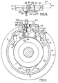
- the brake illustrated in Figures 1-3 of the drawings is of a conventional spreading type in which two rotatable friction discs 1, 2 provided with friction linings and splined on a shaft are adapted to be brought into engagement with spaced opposed radial braking surfaces in a housing 4 by pressure plates 5, 6 located between the discs 1 and centred by three angularly spaced stationary pilots 7, 8, 9. Balls 10 are located in co-operating oppositely inclined recesses 3 in the adjacent faces of the pressure plates 5, 6.
- the application of the brake is initiated by moving the pressure plates 5, 6 angularly in opposite directions which causes the pressure plates 5, 6 to move axially relatively away from each other due to the tendency for the balls 10 to ride up ramps 11 defined by the end faces of the recesses 3. This urges the friction discs 1, 2 into engagement with the braking surfaces in the housing 4.
- the pressure plates 5, 6 are then carried round with the discs until one is arrested by the engagement of a lug 5a, 6a on a respective plate 5, 6 with a drag-taking abutment constituted by the pilot 9, whereafter continued angular movement of the other plate, known as the "servo-plate", provides a servo action.
- the housing 4 comprises a first member 15 in the form of a casting comprising an end wall 16 of which the inner face constitutes one of the radial braking surfaces, and an integral, axially extending, annular flange 17 constituting a radial wall.
- the open face at the free end of the flange 17 is closed by an end plate, not shown, which is bolted to the member 15 by angularly spaced bolts.
- a radial opening 20 in the flange 17 provides a mounting for an hydraulic actuator 22 by means of which the brake is adapted to be applied hydraulically.
- the hydraulic actuator 22 comprises a cylinder 24 having an open-ended longitudinal through-bore in which work a pair of oppositely acting pistons 26, 27 for engagement with lugs 28 and 29 on the plates 5, 6.
- a pressure space defined in bore between adjacent inner ends of the pistons 26 and 27 is connected to a master cylinder through a passage 32, and a bleed passage 33 also leads from the pressure space.
- the cylinder 24 is integral with the inner end of a spigot 34 which depends from a mounting plate 35.
- the plate 35 closes the opening 20 and is detachably secured to the flange 17 by at least two circumferentially spaced bolts 36.
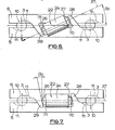
- the longitudinal axis 37 of the bore is tangential to the plates 5, 6, and also lies in a plane which is angled at an angle 8e with respect to a transverse plane parallel to the plane of each plate 5, 6.
- the angle ⁇ e is related to the angle of inclination ⁇ r of the ramp 11 of each recess.
- the mounting plate 35 provides a mounting for a mechanical brake-applying mechanism 40 for applying the brake manually for parking or in an emergency.
- the mounting plate 35 has a pair of axially spaced arms 41 which project from one end of the plate 35 and between the outer ends of which extends a pivot pin 42.
- a bifurcated lever 43 is pivotally mounted at its outer end on the pin 42 and at its opposite inner end has a connection 44 adapted to be coupled to a pull-rod or similar inextensible brake-applying member.
- a trunnion 45 is located at an intermediate point in the length of the lever 43, and the trunnion includes a block 46 which form a pivotal mounting for a wedge assembly 47.
- the wedge assembly 47 comprises a wedge 47 disposed between the balls 10 of an adjacent actuator pair, and a pull-rod 48 which carries the wedge 47 and extends through a radial opening 52 in the flange 17 and an opening in the block 46.
- the pull-rod 48 carries, in screw- threaded engagement at its outer end, an adjusting nut 50 which is in abutment with the block 46, and a lock nut 51.
- the radial opening 52 is spaced circumferentially from the opening 20, and is sealed by a sealing boot 53.
- the pistons 26 and 27 move in opposite directions to urge the two lugs 28 and 29 relatively away from each other to initiate application of the brake. Due to the angle of inclination of the axis 37 of the cylinder 24, the input forces of the pistons 26 and 27 act in directions to move the pressure plates 5, 6 both angularly and axially.
- a brake-applying force applied to the lever 43 moves the lever 43 angularly about the pivot pin 42 as an axis, to withdraw the wedge 47 in a radial direction and separate the balls 10 of the said actuator pair. Due to the engagement of the balls 10 in the recesses 3, the pressure plates 5 and 6 are caused to move angularly in opposite directions and initiate application of the brake, as described above.
- the effective length of the pull-rod 48 can be adjusted to compensate for wear of the friction linings by adjusting the positions of the nuts 50, 51.
- the mechanical brake-applying mechanism 40 projects into the brake through the radial opening 20.
- the brake-applying mechanism 40 comprises a bell-crank lever 60 which is pivotally connected to the plate 5 by means of a pivot pin 61.
- the lever 60 has a part- circular nose 62 which co-operates with the lug 29 on the plate 6 which is extended axially across the plate 5.
- the lever 60 is adapted to be moved angularly about the pivot by means of a pull-rod 61 which, in turn, is coupled at its outer end to a lever 62.
- the lever 62 is pivotably mounted at one end on a pivotal connection 63 on the mounting plate 35 so that a brake-applying force applied to the opposite end is operative to withdraw the pull-rod 61 from the housing 4, at the same time moving the bell-crank lever 60 angularly, in turn to urge the two plates 5 and 6 angularly, relatively away from each other.
- the bell-crank lever 60 is parallel to the axis 37 so that it is also angled at an angle of 8e, and therefore applies input loads to the plates 5 and 6 in a similar direction and manner to that of the hydraulic actuator 22.
- the pivot pin 61 has a stem of conical profile which is received in a circular opening in the bell-crank lever 60 in order to align the lever 60, and the pin 61 is screwed into a tapped hole in the plate 6 which is normal to the plane of that plate, to facilitate manufacture.
- the tolerances between the pilot lugs 7 and 8 and the pressure plates 5 and 6 are chosen to bring the offset of the faces on the pressure plates 5 and 6, which co-operate with the lugs 7 and 8, to a zero value in an assembled condition.
- An additional machining operation may be necessary to achieve the necessary tolerances at the pilot faces.
- the axial component of the brake-applying force is applied by the pistons 26, 27 to the lugs 28, 29 in a direction so that at least the balls 10 adjacent to the actuator 22 are loaded onto the recesses 3. This ensures that those balls 10 closely follow the respective ramps 11.
- the pivot point is transferred from the balls 10 diametrically opposite the actuator 22 to the balls 10 adjacent to the actuator 22. Even if an angle appears between the actuator 22 and relative to any pivot point on the balls 10, any tendency for the plates 5 and 6 to lift will be relatively small, and substantially one- third in comparison with the embodiment of Figures 1 to 4, and Figures 5 and 6, and the relative lift between the two plates 5 and 6 is substantially eliminated. Existing tolerances between the pilot lugs 7 and 8 and the pressure plates 5 and 6 can be maintained, and no additional machining operation will therefore be required to bring the offset of the pilot faces of the two pressure plates 5 and 6 to a zero value.
- the axis 37 of the bore of the cylinder 24 is parallel to the plane of the plates, and the abutment faces 70, 71 on the respective lugs 28 and 29 are parallel to each other and are inclined at the angle 6e to a normal to the axis 37.
Landscapes
- Engineering & Computer Science (AREA)
- General Engineering & Computer Science (AREA)
- Mechanical Engineering (AREA)
- Braking Arrangements (AREA)
Applications Claiming Priority (4)
| Application Number | Priority Date | Filing Date | Title |
|---|---|---|---|
| GB858506163A GB8506163D0 (en) | 1985-03-09 | 1985-03-09 | Self-energising disc brakes |
| GB8506163 | 1985-03-09 | ||
| GB8524855 | 1985-10-09 | ||
| GB858524855A GB8524855D0 (en) | 1985-03-09 | 1985-10-09 | Self-energising disc brakes |
Publications (2)
| Publication Number | Publication Date |
|---|---|
| EP0195533A1 true EP0195533A1 (de) | 1986-09-24 |
| EP0195533B1 EP0195533B1 (de) | 1989-04-12 |
Family
ID=26288954
Family Applications (1)
| Application Number | Title | Priority Date | Filing Date |
|---|---|---|---|
| EP86301291A Expired EP0195533B1 (de) | 1985-03-09 | 1986-02-24 | Selbstverstärkende Scheibenbremsen |
Country Status (5)
| Country | Link |
|---|---|
| EP (1) | EP0195533B1 (de) |
| CN (1) | CN86101459A (de) |
| BR (1) | BR8601006A (de) |
| DE (1) | DE3662809D1 (de) |
| ES (1) | ES8701931A1 (de) |
Cited By (2)
| Publication number | Priority date | Publication date | Assignee | Title |
|---|---|---|---|---|
| EP0240127A1 (de) * | 1986-02-26 | 1987-10-07 | LUCAS INDUSTRIES public limited company | Selbstverstärkende Scheibenbremsen |
| EP0304168A1 (de) * | 1987-07-22 | 1989-02-22 | LUCAS INDUSTRIES public limited company | Selbstverstärkend wirkende Scheibenbremse |
Families Citing this family (3)
| Publication number | Priority date | Publication date | Assignee | Title |
|---|---|---|---|---|
| FR2893912B1 (fr) * | 2005-11-30 | 2008-02-08 | Messier Bugatti Sa | Frein electromecanique, notamment pour aeronef, avec actionneurs ayant un debattement angulaire |
| JP5532246B2 (ja) * | 2010-09-30 | 2014-06-25 | 日立オートモティブシステムズ株式会社 | 推力発生装置、ディスクブレーキ及びスタビライザ |
| JP7530264B2 (ja) * | 2020-10-07 | 2024-08-07 | 住友重機械工業株式会社 | モータ装置 |
Citations (5)
| Publication number | Priority date | Publication date | Assignee | Title |
|---|---|---|---|---|
| GB1147892A (en) * | 1965-07-12 | 1969-04-10 | Lambert & Brake Corp | Self adjusting friction devices |
| DE2640304A1 (de) * | 1976-09-08 | 1978-03-09 | Kloeckner Humboldt Deutz Ag | Scheibenbremse, insbesondere fuer landwirtschaftlich nutzbare kraftfahrzeuge |
| GB2014261A (en) * | 1978-02-11 | 1979-08-22 | Girling Ltd | Disc Brakes for Vehicles |
| EP0040027A1 (de) * | 1980-05-09 | 1981-11-18 | LUCAS INDUSTRIES public limited company | Scheibenbremsen |
| EP0108591A1 (de) * | 1982-11-06 | 1984-05-16 | LUCAS INDUSTRIES public limited company | Scheibenbremsen für Fahrzeuge |
Family Cites Families (1)
| Publication number | Priority date | Publication date | Assignee | Title |
|---|---|---|---|---|
| US2955681A (en) * | 1954-01-13 | 1960-10-11 | Bendix Corp | Disk brake |
-
1986
- 1986-02-24 DE DE8686301291T patent/DE3662809D1/de not_active Expired
- 1986-02-24 EP EP86301291A patent/EP0195533B1/de not_active Expired
- 1986-03-07 ES ES552785A patent/ES8701931A1/es not_active Expired
- 1986-03-07 BR BR8601006A patent/BR8601006A/pt not_active IP Right Cessation
- 1986-03-08 CN CN198686101459A patent/CN86101459A/zh active Pending
Patent Citations (5)
| Publication number | Priority date | Publication date | Assignee | Title |
|---|---|---|---|---|
| GB1147892A (en) * | 1965-07-12 | 1969-04-10 | Lambert & Brake Corp | Self adjusting friction devices |
| DE2640304A1 (de) * | 1976-09-08 | 1978-03-09 | Kloeckner Humboldt Deutz Ag | Scheibenbremse, insbesondere fuer landwirtschaftlich nutzbare kraftfahrzeuge |
| GB2014261A (en) * | 1978-02-11 | 1979-08-22 | Girling Ltd | Disc Brakes for Vehicles |
| EP0040027A1 (de) * | 1980-05-09 | 1981-11-18 | LUCAS INDUSTRIES public limited company | Scheibenbremsen |
| EP0108591A1 (de) * | 1982-11-06 | 1984-05-16 | LUCAS INDUSTRIES public limited company | Scheibenbremsen für Fahrzeuge |
Cited By (2)
| Publication number | Priority date | Publication date | Assignee | Title |
|---|---|---|---|---|
| EP0240127A1 (de) * | 1986-02-26 | 1987-10-07 | LUCAS INDUSTRIES public limited company | Selbstverstärkende Scheibenbremsen |
| EP0304168A1 (de) * | 1987-07-22 | 1989-02-22 | LUCAS INDUSTRIES public limited company | Selbstverstärkend wirkende Scheibenbremse |
Also Published As
| Publication number | Publication date |
|---|---|
| BR8601006A (pt) | 1986-11-18 |
| CN86101459A (zh) | 1986-11-26 |
| EP0195533B1 (de) | 1989-04-12 |
| ES8701931A1 (es) | 1986-12-01 |
| DE3662809D1 (en) | 1989-05-18 |
| ES552785A0 (es) | 1986-12-01 |
Similar Documents
| Publication | Publication Date | Title |
|---|---|---|
| US4653614A (en) | Self-energizing disc brakes | |
| EP0040027B1 (de) | Scheibenbremsen | |
| EP0196766B1 (de) | Selbstverstärkende Scheibenbremsen | |
| EP0110637B1 (de) | Scheibenbremsen für Fahrzeuge | |
| EP0195533B1 (de) | Selbstverstärkende Scheibenbremsen | |
| EP0190828B1 (de) | Scheibenbremsen mit Selbstverstärkung | |
| US4795003A (en) | Self-energizing disc brakes | |
| EP0192396A1 (de) | Selbstverstärkende Scheibenbremse | |
| US4089392A (en) | Self-energizing disc brakes and actuator therefor | |
| US4549636A (en) | Disc brakes for vehicles | |
| EP0192395A1 (de) | Selbstverstärkende Scheibenbremse | |
| US4676345A (en) | Self-energizing disc brakes | |
| EP0495311A1 (de) | Bremsbetätigungsvorrichtung | |
| EP0033032A1 (de) | Scheibenbremsen für Kraftfahrzeuge | |
| EP0224341A1 (de) | Selbstverstärkend wirkende Scheibenbremse | |
| US4702351A (en) | Self-energizing disc brakes | |
| EP0240127B1 (de) | Selbstverstärkende Scheibenbremsen | |
| US4768624A (en) | Self-energizing disc brakes with cable assembly and cable casing therefor | |
| EP0213869A2 (de) | Selbstverstärkende Scheibenbremse | |
| EP0304168A1 (de) | Selbstverstärkend wirkende Scheibenbremse | |
| EP0236027A1 (de) | Selbstverstärkende Scheibenbremsen | |
| EP0316070A1 (de) | Selbstverstärkend wirkende Scheibenbremse | |
| US4722423A (en) | Brake actuating mechanism | |
| EP0188339A2 (de) | Selbstverstärkende Scheibenbremsen | |
| EP0237158A1 (de) | Selbstverstärkende Scheibenbremsen |
Legal Events
| Date | Code | Title | Description |
|---|---|---|---|
| PUAI | Public reference made under article 153(3) epc to a published international application that has entered the european phase |
Free format text: ORIGINAL CODE: 0009012 |
|
| AK | Designated contracting states |
Kind code of ref document: A1 Designated state(s): DE FR GB IT |
|
| 17P | Request for examination filed |
Effective date: 19870228 |
|
| 17Q | First examination report despatched |
Effective date: 19880318 |
|
| GRAA | (expected) grant |
Free format text: ORIGINAL CODE: 0009210 |
|
| AK | Designated contracting states |
Kind code of ref document: B1 Designated state(s): DE FR GB IT |
|
| ITF | It: translation for a ep patent filed | ||
| REF | Corresponds to: |
Ref document number: 3662809 Country of ref document: DE Date of ref document: 19890518 |
|
| ET | Fr: translation filed | ||
| PGFP | Annual fee paid to national office [announced via postgrant information from national office to epo] |
Ref country code: FR Payment date: 19900202 Year of fee payment: 5 |
|
| PLBE | No opposition filed within time limit |
Free format text: ORIGINAL CODE: 0009261 |
|
| STAA | Information on the status of an ep patent application or granted ep patent |
Free format text: STATUS: NO OPPOSITION FILED WITHIN TIME LIMIT |
|
| 26N | No opposition filed | ||
| PGFP | Annual fee paid to national office [announced via postgrant information from national office to epo] |
Ref country code: DE Payment date: 19900420 Year of fee payment: 5 |
|
| ITTA | It: last paid annual fee | ||
| PG25 | Lapsed in a contracting state [announced via postgrant information from national office to epo] |
Ref country code: FR Effective date: 19911031 |
|
| PG25 | Lapsed in a contracting state [announced via postgrant information from national office to epo] |
Ref country code: DE Effective date: 19911101 |
|
| REG | Reference to a national code |
Ref country code: FR Ref legal event code: ST |
|
| REG | Reference to a national code |
Ref country code: GB Ref legal event code: IF02 |
|
| REG | Reference to a national code |
Ref country code: GB Ref legal event code: 732E |
|
| REG | Reference to a national code |
Ref country code: GB Ref legal event code: 732E |
|
| PGFP | Annual fee paid to national office [announced via postgrant information from national office to epo] |
Ref country code: GB Payment date: 20050216 Year of fee payment: 20 |
|
| PGFP | Annual fee paid to national office [announced via postgrant information from national office to epo] |
Ref country code: IT Payment date: 20050226 Year of fee payment: 20 |
|
| REG | Reference to a national code |
Ref country code: GB Ref legal event code: PE20 |
|
| PG25 | Lapsed in a contracting state [announced via postgrant information from national office to epo] |
Ref country code: GB Free format text: LAPSE BECAUSE OF EXPIRATION OF PROTECTION Effective date: 20060223 |
|
| REG | Reference to a national code |
Ref country code: GB Ref legal event code: 732E |