EP0196766B1 - Selbstverstärkende Scheibenbremsen - Google Patents
Selbstverstärkende Scheibenbremsen Download PDFInfo
- Publication number
- EP0196766B1 EP0196766B1 EP86301292A EP86301292A EP0196766B1 EP 0196766 B1 EP0196766 B1 EP 0196766B1 EP 86301292 A EP86301292 A EP 86301292A EP 86301292 A EP86301292 A EP 86301292A EP 0196766 B1 EP0196766 B1 EP 0196766B1
- Authority
- EP
- European Patent Office
- Prior art keywords
- brake
- housing
- pressure plates
- brake according
- plate
- Prior art date
- Legal status (The legal status is an assumption and is not a legal conclusion. Google has not performed a legal analysis and makes no representation as to the accuracy of the status listed.)
- Expired
Links
Images



Classifications
-
- F—MECHANICAL ENGINEERING; LIGHTING; HEATING; WEAPONS; BLASTING
- F16—ENGINEERING ELEMENTS AND UNITS; GENERAL MEASURES FOR PRODUCING AND MAINTAINING EFFECTIVE FUNCTIONING OF MACHINES OR INSTALLATIONS; THERMAL INSULATION IN GENERAL
- F16D—COUPLINGS FOR TRANSMITTING ROTATION; CLUTCHES; BRAKES
- F16D55/00—Brakes with substantially-radial braking surfaces pressed together in axial direction, e.g. disc brakes
- F16D55/02—Brakes with substantially-radial braking surfaces pressed together in axial direction, e.g. disc brakes with axially-movable discs or pads pressed against axially-located rotating members
- F16D55/04—Brakes with substantially-radial braking surfaces pressed together in axial direction, e.g. disc brakes with axially-movable discs or pads pressed against axially-located rotating members by moving discs or pads away from one another against radial walls of drums or cylinders
- F16D55/14—Brakes with substantially-radial braking surfaces pressed together in axial direction, e.g. disc brakes with axially-movable discs or pads pressed against axially-located rotating members by moving discs or pads away from one another against radial walls of drums or cylinders with self-tightening action, e.g. by means of coacting helical surfaces or balls and inclined surfaces
-
- F—MECHANICAL ENGINEERING; LIGHTING; HEATING; WEAPONS; BLASTING
- F16—ENGINEERING ELEMENTS AND UNITS; GENERAL MEASURES FOR PRODUCING AND MAINTAINING EFFECTIVE FUNCTIONING OF MACHINES OR INSTALLATIONS; THERMAL INSULATION IN GENERAL
- F16D—COUPLINGS FOR TRANSMITTING ROTATION; CLUTCHES; BRAKES
- F16D2125/00—Components of actuators
- F16D2125/18—Mechanical mechanisms
- F16D2125/20—Mechanical mechanisms converting rotation to linear movement or vice versa
- F16D2125/34—Mechanical mechanisms converting rotation to linear movement or vice versa acting in the direction of the axis of rotation
- F16D2125/36—Helical cams, Ball-rotating ramps
-
- F—MECHANICAL ENGINEERING; LIGHTING; HEATING; WEAPONS; BLASTING
- F16—ENGINEERING ELEMENTS AND UNITS; GENERAL MEASURES FOR PRODUCING AND MAINTAINING EFFECTIVE FUNCTIONING OF MACHINES OR INSTALLATIONS; THERMAL INSULATION IN GENERAL
- F16D—COUPLINGS FOR TRANSMITTING ROTATION; CLUTCHES; BRAKES
- F16D2125/00—Components of actuators
- F16D2125/18—Mechanical mechanisms
- F16D2125/58—Mechanical mechanisms transmitting linear movement
- F16D2125/68—Lever-link mechanisms, e.g. toggles with change of force ratio
Definitions
- This invention relates to self-energising disc brakes of the kind in which rotatable friction discs provided with linings of friction material are adapted to be brought into engagement with spaced opposed braking surfaces in a housing by pressure plates located between the friction discs and centred by stationary pilot lugs, balls or rollers are located in co-operating oppositely inclined recesses in the adjacent faces of the pressure plates, and the application of the brake is initiated by moving the pressure plates angularly in opposite directions, the pressure plates then moving apart, due to the tendency for the balls or rollers to ride up ramps defined by the edges of the recesses, and into engagement with the friction discs which are urged into engagement with the braking surfaces, and the pressure plates are carried round with the friction discs until one is arrested by the engagement of a lug on the plate with a drag-taking stop abutment in the housing, the continued angular movement of the other pressure plate providing a servo action.
- Self-energising brakes of the kind set forth may be dry or they may be of the liquid cooled type, and such brakes are commonly used in tractors and like vehicles and are hereinafter calles brakes of the kind set forth.
- the hydraulic actuator comprises a stepped piston working in a radial bore in a cylinder member attached to the housing of the brake and acting on the pressure plates through a thrust coupling on a pull-rod which extends, with substantial clearance, through the piston, and the mechanically operable means acts on the pull-rod independently of the piston.
- GB-A-2 014 261 discloses a self-energising disc brake of the kind set forth provided with an actuator unit incorporating hydraulically-operable means and mechanically-operable means, the unit comprises a complex casting member having a protruding portion, the radially inner surface of which defines a cavity.
- the casting is secured to the housing and provides a mounting for both the mechanically and hydraulically operable means which extend into the housing through a common radial opening.
- the hydraulically-operable means acts on lug on one of the pressure plates and comprises a cylinder body having a longitudinal bore of which the axis is tangential to the plates and in which works a piston for co-operation with the lug.
- the cavity is located radially outside of the common radial opening.
- the mechanically operable means is received in part in the cavity formed in the casting and extends from the cavity through the common radial opening and into the housing.
- a self-energising disc brake in which rotatable friction discs provided with linings of friction material are adapted to be brought into engagement with spaced opposed braking surfaces in a housing by pressure plates located between the friction discs and centred by stationary pilot lugs, balls or rollers are located in co-operating oppositely inclined recesses in the adjacent faces of the pressure plates, and the application of the brake is initiated by moving the pressure plates in opposite directions, the pressure plates then moving apart, due to the tendency for the balls or rollers to ride up ramps defined by the edges of the recesses, and into engagement with the friction discs which are urged into engagement with the braking surfaces, and the pressure plates are carried round with the friction discs until one is arrested by the engagement of a lug on the plate with a drag-taking stop abutment in the housing, the continued angular movement of the other pressure plate providing a servo action, and the brake is provided with an actuator unit incorporating hydraulically-operable means and mechanically-operable means, the unit comprising
- the bore extends between opposite ends of the cylinder body and two pistons working in the bore act between the lugs on the plates.
- the two means are operable independent of each other which increases reliability and providing a common opening in the housing facilitates machining on existing lines, and allows freedom of choice for the location of the brake input position.
- the actuator unit may be detachably mounted on the housing, suitably by the use of detachable bolts for clamping the closure plate against a region of the housing which surrounds the radial opening. This improves serviceability and facilitates sealing.
- the mechanically-operable means may be of any convenient construction, including a linkage which is accessible from the exterior of the housing through an opening in the plate.
- the mechanically-operable means includes suitable means for adjusting the effective length of the linkage of the mechanically-operable means, and, conveniently, such adjuster means are also accessible from the exterior of the housing.
- the brake illustrated in Figures 1-6 of the drawings is of a conventional spreading type in which two rotatable friction discs 1, 2 provided with friction linings and splined on a shaft are adapted to be brought into engagement with spaced opposed radial braking surfaces in a housing 4 by pressure plates 5, 6 located between the discs 1 and centred by three angularly spaced stationary pilots 7, 8, 9. Balls 10 are located in co-operating oppositely inclined recesses 3 in the adjacent faces of the pressure plates 5, 6.
- the application of the brake is initiated by moving the pressure plates 5, 6 angularly in opposite directions which causes the pressure plates 5, 6 to move axially relatively away from each other due to the tendency for the balls 10 to ride up ramps 11 defined by the end faces of the recesses 3. This urges the friction discs 1, 2 into engagement with the braking surfaces in the housing 4.
- the pressure plates 5, 6 are then carried round with the discs until one is arrested by the engagement of a lug 5a, 6a on a respective plate 5, 6 with a drag-taking abutment constituted by the pilot 9, whereafter continued angular movement of the other plate known as the «servo plate», provides a servo action.
- the housing 4 comprises a first member 15 in the form of a casting comprising an end wall 16 of which the inner face constitutes one of the radial braking surfaces, and an integral, axially extending, annular flange constituting a radial wall 17.
- the open face at the free end of the flange 17 is closed by an end plate, not shown, which is bolted to the member 15 by angularly spaced bolts.
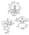
- a radial opening 20 in the flange 17 provides a mounting for an actuator unit 21 by means of which the brake is adapted to be applied hydraulically for normal service braking, and mechanically for parking or emergency braking.
- the unit 21 comprises an hydraulic cylinder 24 having an open-ended longitudinal throughbore in which work a pair of oppositely acting pistons 26, 27 for engagement with lugs 28 and 29 on the plates 5, 6.
- a pressure space defined in the bore between adjacent inner ends of the pistons 26 and 27 is connected to a master cylinder through a passage 32, and a bleed passage 33 also leads from the pressure space.
- the cylinder 24 is integral with the inner end of a spigot 34 which depends from a mounting plate 35.
- the plate 35 closes the opening 20 and is detachably secured to the flange 17 by a least two circumferentially spaced bolts 36.
- a sealing gasket 37 is clamped between the mating faces of the plate 35 and the housing 4.
- the longitudinal axis of the bore is tangential to the plates 5, 6, and also lies in a transverse plane parallel to the plane of each plate 5, 6.
- the mounting plate 35 provides a mounting for a mechanical brake-applying mechanism 40 for applying the brake manually for parking or in an emergency.
- the brake-applying mechanism 40 comprises a bifurcated lever 41 which is pivotally connected at one end to opposite ends of a transverse pivot pin 42 which project from opposite sides of a lug 43 which is upstanding from the plate 35 and is disposed on one side of the projected area of the cylinder 24.
- the opposite end of the lever 41 is provided with an opening for connection to a brake-applying pull-rod or cable 44 ( Figure 6).
- a trunnion 45 is located at an intermediate point in the length of the lever 41, and the trunnion includes a block 46 which forms a pivotal mounting for the outer end of a pull-rod 47 of which the inner end is connected by a pin 48 to one arm of a bell-crank lever 49.
- the lever 49 is pivotally connected to the plate 6 by means of a pivot pin 50, and the lever has a part-circular nose 51 which cooperates with a face 52 on the lug 29 which is extended axially across the plate 6.
- the pull-rod 47 extends into the brake through an opening 53 in the plate 35, and the opening 53 is closed by a resilient boot 54 of which the outer edge is secured to the plate 35 surrounding the opening 53 and the inner edge is secured to the rod 47.
- the pullrod 47 also carries, in screw- threaded engagement at its outer end, an adjusting nut 55, which is in abutment with the block 46, and a lock nut 56.
- the bell-crank lever 49 is replaced by a pair of toggle links 60, 61, each of which is pivotally connected at ist outer end to a respective one of the lugs 28, 29 by means of pivotal connections 62,63.
- the longitudinal axis of the bore of the cylinder 24 also lies in plane which is angled with respect to a transverse plane parallel to the plane of each plate 5, 6, and the bell-crank lever 49 is similarly angled with respect to the plates to lie in a plane parallel to the said axis.
- the pivot pin 50 has a stem of conical profile which is received in a circular opening in the bell-crank lever 49 in order to align the lever 49, and the pin 50 is screwed into a tapped hole in the plate 6 which is normal to the plane of that plate, to facilitate manufacture.
Landscapes
- Engineering & Computer Science (AREA)
- General Engineering & Computer Science (AREA)
- Mechanical Engineering (AREA)
- Braking Arrangements (AREA)
Claims (12)
Applications Claiming Priority (2)
| Application Number | Priority Date | Filing Date | Title |
|---|---|---|---|
| GB8506164 | 1985-03-09 | ||
| GB858506164A GB8506164D0 (en) | 1985-03-09 | 1985-03-09 | Self-energising disc brakes |
Publications (2)
| Publication Number | Publication Date |
|---|---|
| EP0196766A1 EP0196766A1 (de) | 1986-10-08 |
| EP0196766B1 true EP0196766B1 (de) | 1989-04-12 |
Family
ID=10575749
Family Applications (1)
| Application Number | Title | Priority Date | Filing Date |
|---|---|---|---|
| EP86301292A Expired EP0196766B1 (de) | 1985-03-09 | 1986-02-24 | Selbstverstärkende Scheibenbremsen |
Country Status (10)
| Country | Link |
|---|---|
| US (1) | US4685541A (de) |
| EP (1) | EP0196766B1 (de) |
| JP (1) | JPS61236933A (de) |
| CN (1) | CN1004977B (de) |
| BR (1) | BR8601005A (de) |
| DE (1) | DE3662810D1 (de) |
| ES (1) | ES8701932A1 (de) |
| GB (1) | GB8506164D0 (de) |
| PL (1) | PL147033B1 (de) |
| YU (1) | YU32286A (de) |
Families Citing this family (10)
| Publication number | Priority date | Publication date | Assignee | Title |
|---|---|---|---|---|
| GB8603107D0 (en) * | 1986-02-07 | 1986-03-12 | Lucas Ind Plc | Self-energising disc brakes |
| GB8904852D0 (en) * | 1989-03-02 | 1989-04-12 | Lucas Ind Plc | Disc brakes for vehicles |
| US5024298A (en) * | 1989-05-17 | 1991-06-18 | General Motors Corporation | Apparatus and method of automotive brake with booster piston |
| US5036960A (en) * | 1990-05-17 | 1991-08-06 | General Motors Corporation | Apparatus and method of automotive brake with booster piston |
| CN101065597B (zh) * | 2004-10-13 | 2011-03-30 | 克诺尔商用车制动系统有限公司 | 按自行增力的结构形式的盘式制动器和用于自行增力的制动器的控制方法 |
| US7556128B2 (en) * | 2005-10-31 | 2009-07-07 | Warner Electric Technology Llc | Dual actuator friction brake assembly |
| KR100861872B1 (ko) * | 2007-08-31 | 2008-10-06 | 현대모비스 주식회사 | 볼 인 램프 브레이크 캘리퍼 타입 차량의 주차 브레이크 |
| CN103644217B (zh) * | 2013-12-10 | 2016-02-17 | 临沂高新区鸿图电子有限公司 | 一种肘杆增力式电子机械制动器 |
| CN112065887A (zh) * | 2020-09-11 | 2020-12-11 | 山东时利和精工机械有限公司 | 一种自增力制动器总成 |
| DE102022203002B3 (de) | 2022-03-28 | 2023-09-07 | Zf Friedrichshafen Ag | Betätigungseinrichtung für eine Bremse |
Citations (1)
| Publication number | Priority date | Publication date | Assignee | Title |
|---|---|---|---|---|
| GB2014261A (en) * | 1978-02-11 | 1979-08-22 | Girling Ltd | Disc Brakes for Vehicles |
Family Cites Families (11)
| Publication number | Priority date | Publication date | Assignee | Title |
|---|---|---|---|---|
| GB726594A (en) * | 1953-04-22 | 1955-03-23 | Girling Ltd | Improvements in or relating to actuating means for internal shoe-drum brakes |
| US3101813A (en) * | 1960-04-08 | 1963-08-27 | Lambert & Brake Corp | Disc type brake structure |
| GB1022974A (en) * | 1962-02-28 | 1966-03-16 | Klaue Hermann | Axially spreading brake of the segmental brake pad type |
| DE1273922B (de) * | 1964-01-07 | 1968-07-25 | Teves Gmbh Alfred | Selbstverstaerkend wirkende, hydraulisch oder mechanisch betaetigte Teilbelagscheibenbremse, insbesondere fuer Fahrzeuge |
| US3392805A (en) * | 1966-10-27 | 1968-07-16 | Lambert & Brake Corp | Adjustable brake actuating mechanism |
| DE1937770A1 (de) * | 1969-07-25 | 1971-02-04 | Kloeckner Humboldt Deutz Ag | Scheibenbremse |
| GB1531168A (en) * | 1976-08-19 | 1978-11-01 | Girling Ltd | Self-energising disc brakes |
| DE2640304A1 (de) * | 1976-09-08 | 1978-03-09 | Kloeckner Humboldt Deutz Ag | Scheibenbremse, insbesondere fuer landwirtschaftlich nutzbare kraftfahrzeuge |
| GB2031083B (en) * | 1978-09-26 | 1982-08-11 | Lucas Industries Ltd | Spreading disc brakes for vehicles |
| US4241813A (en) * | 1979-06-29 | 1980-12-30 | The Bendix Corporation | Band brake parking lever |
| US4383593A (en) * | 1980-05-09 | 1983-05-17 | Lucas Industries Limited | Hydraulically and mechanically operable disc brakes |
-
1985
- 1985-03-09 GB GB858506164A patent/GB8506164D0/en active Pending
-
1986
- 1986-02-24 EP EP86301292A patent/EP0196766B1/de not_active Expired
- 1986-02-24 DE DE8686301292T patent/DE3662810D1/de not_active Expired
- 1986-03-03 US US06/835,172 patent/US4685541A/en not_active Expired - Fee Related
- 1986-03-05 YU YU00322/86A patent/YU32286A/xx unknown
- 1986-03-07 PL PL1986258292A patent/PL147033B1/pl unknown
- 1986-03-07 JP JP61050260A patent/JPS61236933A/ja active Granted
- 1986-03-07 BR BR8601005A patent/BR8601005A/pt not_active IP Right Cessation
- 1986-03-07 ES ES552786A patent/ES8701932A1/es not_active Expired
- 1986-03-08 CN CN86101461.8A patent/CN1004977B/zh not_active Expired
Patent Citations (1)
| Publication number | Priority date | Publication date | Assignee | Title |
|---|---|---|---|---|
| GB2014261A (en) * | 1978-02-11 | 1979-08-22 | Girling Ltd | Disc Brakes for Vehicles |
Also Published As
| Publication number | Publication date |
|---|---|
| DE3662810D1 (en) | 1989-05-18 |
| GB8506164D0 (en) | 1985-04-11 |
| PL147033B1 (en) | 1989-04-29 |
| JPH0152613B2 (de) | 1989-11-09 |
| BR8601005A (pt) | 1986-11-18 |
| CN1004977B (zh) | 1989-08-09 |
| YU32286A (en) | 1989-04-30 |
| ES552786A0 (es) | 1986-12-01 |
| CN86101461A (zh) | 1986-10-29 |
| JPS61236933A (ja) | 1986-10-22 |
| EP0196766A1 (de) | 1986-10-08 |
| US4685541A (en) | 1987-08-11 |
| ES8701932A1 (es) | 1986-12-01 |
Similar Documents
| Publication | Publication Date | Title |
|---|---|---|
| US4653614A (en) | Self-energizing disc brakes | |
| EP0196766B1 (de) | Selbstverstärkende Scheibenbremsen | |
| EP0040027B1 (de) | Scheibenbremsen | |
| EP0110637B1 (de) | Scheibenbremsen für Fahrzeuge | |
| EP0190828B1 (de) | Scheibenbremsen mit Selbstverstärkung | |
| US4795003A (en) | Self-energizing disc brakes | |
| EP0195533B1 (de) | Selbstverstärkende Scheibenbremsen | |
| US4089392A (en) | Self-energizing disc brakes and actuator therefor | |
| EP0033032B1 (de) | Scheibenbremsen für Kraftfahrzeuge | |
| EP0192396A1 (de) | Selbstverstärkende Scheibenbremse | |
| US5033591A (en) | Disc brakes for vehicles | |
| US4676345A (en) | Self-energizing disc brakes | |
| US4549636A (en) | Disc brakes for vehicles | |
| GB2075623A (en) | Disc brakes | |
| EP0224341A1 (de) | Selbstverstärkend wirkende Scheibenbremse | |
| EP0192395A1 (de) | Selbstverstärkende Scheibenbremse | |
| US4722423A (en) | Brake actuating mechanism | |
| US4768625A (en) | Self-energizing disc brakes | |
| US4711327A (en) | Self-energizing disc brakes | |
| EP0188339A2 (de) | Selbstverstärkende Scheibenbremsen | |
| EP0304168A1 (de) | Selbstverstärkend wirkende Scheibenbremse | |
| EP0097447A1 (de) | Scheibenbremsen für Fahrzeuge | |
| EP0236027A1 (de) | Selbstverstärkende Scheibenbremsen | |
| EP0237158A1 (de) | Selbstverstärkende Scheibenbremsen | |
| JPH0152614B2 (de) |
Legal Events
| Date | Code | Title | Description |
|---|---|---|---|
| PUAI | Public reference made under article 153(3) epc to a published international application that has entered the european phase |
Free format text: ORIGINAL CODE: 0009012 |
|
| AK | Designated contracting states |
Kind code of ref document: A1 Designated state(s): DE FR GB IT |
|
| 17P | Request for examination filed |
Effective date: 19870312 |
|
| 17Q | First examination report despatched |
Effective date: 19880324 |
|
| GRAA | (expected) grant |
Free format text: ORIGINAL CODE: 0009210 |
|
| AK | Designated contracting states |
Kind code of ref document: B1 Designated state(s): DE FR GB IT |
|
| ITF | It: translation for a ep patent filed | ||
| REF | Corresponds to: |
Ref document number: 3662810 Country of ref document: DE Date of ref document: 19890518 |
|
| ET | Fr: translation filed | ||
| PGFP | Annual fee paid to national office [announced via postgrant information from national office to epo] |
Ref country code: FR Payment date: 19900202 Year of fee payment: 5 |
|
| PLBE | No opposition filed within time limit |
Free format text: ORIGINAL CODE: 0009261 |
|
| STAA | Information on the status of an ep patent application or granted ep patent |
Free format text: STATUS: NO OPPOSITION FILED WITHIN TIME LIMIT |
|
| 26N | No opposition filed | ||
| PGFP | Annual fee paid to national office [announced via postgrant information from national office to epo] |
Ref country code: DE Payment date: 19900420 Year of fee payment: 5 |
|
| ITTA | It: last paid annual fee | ||
| PG25 | Lapsed in a contracting state [announced via postgrant information from national office to epo] |
Ref country code: FR Effective date: 19911031 |
|
| PG25 | Lapsed in a contracting state [announced via postgrant information from national office to epo] |
Ref country code: DE Effective date: 19911101 |
|
| REG | Reference to a national code |
Ref country code: FR Ref legal event code: ST |
|
| REG | Reference to a national code |
Ref country code: GB Ref legal event code: IF02 |
|
| PGFP | Annual fee paid to national office [announced via postgrant information from national office to epo] |
Ref country code: GB Payment date: 20050216 Year of fee payment: 20 |
|
| PGFP | Annual fee paid to national office [announced via postgrant information from national office to epo] |
Ref country code: IT Payment date: 20050226 Year of fee payment: 20 |
|
| REG | Reference to a national code |
Ref country code: GB Ref legal event code: PE20 |
|
| REG | Reference to a national code |
Ref country code: GB Ref legal event code: 732E |
|
| PG25 | Lapsed in a contracting state [announced via postgrant information from national office to epo] |
Ref country code: GB Free format text: LAPSE BECAUSE OF EXPIRATION OF PROTECTION Effective date: 20060223 |
|
| REG | Reference to a national code |
Ref country code: GB Ref legal event code: 732E |