EP0195628B1 - Tête magnétique - Google Patents
Tête magnétique Download PDFInfo
- Publication number
- EP0195628B1 EP0195628B1 EP86301921A EP86301921A EP0195628B1 EP 0195628 B1 EP0195628 B1 EP 0195628B1 EP 86301921 A EP86301921 A EP 86301921A EP 86301921 A EP86301921 A EP 86301921A EP 0195628 B1 EP0195628 B1 EP 0195628B1
- Authority
- EP
- European Patent Office
- Prior art keywords
- magnetic
- thin film
- film
- magnetic thin
- magnetic head
- Prior art date
- Legal status (The legal status is an assumption and is not a legal conclusion. Google has not performed a legal analysis and makes no representation as to the accuracy of the status listed.)
- Expired
Links
- 230000005291 magnetic effect Effects 0.000 title claims description 161
- 239000010409 thin film Substances 0.000 claims description 96
- 239000010408 film Substances 0.000 claims description 55
- 230000000694 effects Effects 0.000 claims description 16
- 230000035699 permeability Effects 0.000 claims description 16
- 230000003287 optical effect Effects 0.000 claims description 15
- 239000000696 magnetic material Substances 0.000 claims description 11
- 230000010287 polarization Effects 0.000 claims 1
- 239000010410 layer Substances 0.000 description 34
- 230000005415 magnetization Effects 0.000 description 30
- VYPSYNLAJGMNEJ-UHFFFAOYSA-N Silicium dioxide Chemical compound O=[Si]=O VYPSYNLAJGMNEJ-UHFFFAOYSA-N 0.000 description 14
- 229910045601 alloy Inorganic materials 0.000 description 11
- 239000000956 alloy Substances 0.000 description 11
- 238000000034 method Methods 0.000 description 10
- 239000000758 substrate Substances 0.000 description 10
- 230000005374 Kerr effect Effects 0.000 description 9
- 230000004907 flux Effects 0.000 description 9
- 229910000859 α-Fe Inorganic materials 0.000 description 9
- 238000006243 chemical reaction Methods 0.000 description 7
- 229910052681 coesite Inorganic materials 0.000 description 7
- 229910052906 cristobalite Inorganic materials 0.000 description 7
- 239000000377 silicon dioxide Substances 0.000 description 7
- 235000012239 silicon dioxide Nutrition 0.000 description 7
- 229910052682 stishovite Inorganic materials 0.000 description 7
- 229910052905 tridymite Inorganic materials 0.000 description 7
- 238000004519 manufacturing process Methods 0.000 description 6
- 239000000463 material Substances 0.000 description 6
- 238000004544 sputter deposition Methods 0.000 description 6
- 239000004411 aluminium Substances 0.000 description 5
- 229910052782 aluminium Inorganic materials 0.000 description 5
- XAGFODPZIPBFFR-UHFFFAOYSA-N aluminium Chemical compound [Al] XAGFODPZIPBFFR-UHFFFAOYSA-N 0.000 description 5
- 238000001704 evaporation Methods 0.000 description 5
- 229910020641 Co Zr Inorganic materials 0.000 description 4
- 229910020520 Co—Zr Inorganic materials 0.000 description 4
- 229910002555 FeNi Inorganic materials 0.000 description 4
- 229910001030 Iron–nickel alloy Inorganic materials 0.000 description 4
- -1 for example Substances 0.000 description 4
- 239000011521 glass Substances 0.000 description 4
- 229910009493 Y3Fe5O12 Inorganic materials 0.000 description 3
- 229910000808 amorphous metal alloy Inorganic materials 0.000 description 3
- 230000008859 change Effects 0.000 description 3
- 238000010276 construction Methods 0.000 description 3
- 238000001459 lithography Methods 0.000 description 3
- 125000006850 spacer group Chemical group 0.000 description 3
- 229910000684 Cobalt-chrome Inorganic materials 0.000 description 2
- 229910018605 Ni—Zn Inorganic materials 0.000 description 2
- XUIMIQQOPSSXEZ-UHFFFAOYSA-N Silicon Chemical compound [Si] XUIMIQQOPSSXEZ-UHFFFAOYSA-N 0.000 description 2
- 230000015572 biosynthetic process Effects 0.000 description 2
- 239000010952 cobalt-chrome Substances 0.000 description 2
- 239000002131 composite material Substances 0.000 description 2
- 230000008878 coupling Effects 0.000 description 2
- 238000010168 coupling process Methods 0.000 description 2
- 238000005859 coupling reaction Methods 0.000 description 2
- 238000010586 diagram Methods 0.000 description 2
- 230000008020 evaporation Effects 0.000 description 2
- 230000005284 excitation Effects 0.000 description 2
- 239000002223 garnet Substances 0.000 description 2
- 230000005381 magnetic domain Effects 0.000 description 2
- 238000000059 patterning Methods 0.000 description 2
- 229910000889 permalloy Inorganic materials 0.000 description 2
- 229910052761 rare earth metal Inorganic materials 0.000 description 2
- 239000011347 resin Substances 0.000 description 2
- 229920005989 resin Polymers 0.000 description 2
- 230000035945 sensitivity Effects 0.000 description 2
- 239000010703 silicon Substances 0.000 description 2
- 229910052710 silicon Inorganic materials 0.000 description 2
- 229910001199 N alloy Inorganic materials 0.000 description 1
- GRYLNZFGIOXLOG-UHFFFAOYSA-N Nitric acid Chemical compound O[N+]([O-])=O GRYLNZFGIOXLOG-UHFFFAOYSA-N 0.000 description 1
- 239000000853 adhesive Substances 0.000 description 1
- 230000001070 adhesive effect Effects 0.000 description 1
- 238000005520 cutting process Methods 0.000 description 1
- 238000000609 electron-beam lithography Methods 0.000 description 1
- 230000005294 ferromagnetic effect Effects 0.000 description 1
- 230000006698 induction Effects 0.000 description 1
- 229910052751 metal Inorganic materials 0.000 description 1
- 239000002184 metal Substances 0.000 description 1
- 239000005300 metallic glass Substances 0.000 description 1
- 229910017604 nitric acid Inorganic materials 0.000 description 1
- 239000012788 optical film Substances 0.000 description 1
- 238000000206 photolithography Methods 0.000 description 1
- 229920001721 polyimide Polymers 0.000 description 1
- 239000009719 polyimide resin Substances 0.000 description 1
- 150000002910 rare earth metals Chemical class 0.000 description 1
- 239000004065 semiconductor Substances 0.000 description 1
- 239000002356 single layer Substances 0.000 description 1
- 238000000992 sputter etching Methods 0.000 description 1
- 230000001052 transient effect Effects 0.000 description 1
- 229910052723 transition metal Inorganic materials 0.000 description 1
- 238000001771 vacuum deposition Methods 0.000 description 1
Images


Classifications
-
- G—PHYSICS
- G11—INFORMATION STORAGE
- G11B—INFORMATION STORAGE BASED ON RELATIVE MOVEMENT BETWEEN RECORD CARRIER AND TRANSDUCER
- G11B5/00—Recording by magnetisation or demagnetisation of a record carrier; Reproducing by magnetic means; Record carriers therefor
- G11B5/127—Structure or manufacture of heads, e.g. inductive
- G11B5/1278—Structure or manufacture of heads, e.g. inductive specially adapted for magnetisations perpendicular to the surface of the record carrier
-
- G—PHYSICS
- G11—INFORMATION STORAGE
- G11B—INFORMATION STORAGE BASED ON RELATIVE MOVEMENT BETWEEN RECORD CARRIER AND TRANSDUCER
- G11B11/00—Recording on or reproducing from the same record carrier wherein for these two operations the methods are covered by different main groups of groups G11B3/00 - G11B7/00 or by different subgroups of group G11B9/00; Record carriers therefor
- G11B11/10—Recording on or reproducing from the same record carrier wherein for these two operations the methods are covered by different main groups of groups G11B3/00 - G11B7/00 or by different subgroups of group G11B9/00; Record carriers therefor using recording by magnetic means or other means for magnetisation or demagnetisation of a record carrier, e.g. light induced spin magnetisation; Demagnetisation by thermal or stress means in the presence or not of an orienting magnetic field
- G11B11/105—Recording on or reproducing from the same record carrier wherein for these two operations the methods are covered by different main groups of groups G11B3/00 - G11B7/00 or by different subgroups of group G11B9/00; Record carriers therefor using recording by magnetic means or other means for magnetisation or demagnetisation of a record carrier, e.g. light induced spin magnetisation; Demagnetisation by thermal or stress means in the presence or not of an orienting magnetic field using a beam of light or a magnetic field for recording by change of magnetisation and a beam of light for reproducing, i.e. magneto-optical, e.g. light-induced thermomagnetic recording, spin magnetisation recording, Kerr or Faraday effect reproducing
- G11B11/10532—Heads
- G11B11/10534—Heads for recording by magnetising, demagnetising or transfer of magnetisation, by radiation, e.g. for thermomagnetic recording
-
- G—PHYSICS
- G11—INFORMATION STORAGE
- G11B—INFORMATION STORAGE BASED ON RELATIVE MOVEMENT BETWEEN RECORD CARRIER AND TRANSDUCER
- G11B11/00—Recording on or reproducing from the same record carrier wherein for these two operations the methods are covered by different main groups of groups G11B3/00 - G11B7/00 or by different subgroups of group G11B9/00; Record carriers therefor
- G11B11/10—Recording on or reproducing from the same record carrier wherein for these two operations the methods are covered by different main groups of groups G11B3/00 - G11B7/00 or by different subgroups of group G11B9/00; Record carriers therefor using recording by magnetic means or other means for magnetisation or demagnetisation of a record carrier, e.g. light induced spin magnetisation; Demagnetisation by thermal or stress means in the presence or not of an orienting magnetic field
- G11B11/105—Recording on or reproducing from the same record carrier wherein for these two operations the methods are covered by different main groups of groups G11B3/00 - G11B7/00 or by different subgroups of group G11B9/00; Record carriers therefor using recording by magnetic means or other means for magnetisation or demagnetisation of a record carrier, e.g. light induced spin magnetisation; Demagnetisation by thermal or stress means in the presence or not of an orienting magnetic field using a beam of light or a magnetic field for recording by change of magnetisation and a beam of light for reproducing, i.e. magneto-optical, e.g. light-induced thermomagnetic recording, spin magnetisation recording, Kerr or Faraday effect reproducing
- G11B11/10532—Heads
- G11B11/10541—Heads for reproducing
- G11B11/10543—Heads for reproducing using optical beam of radiation
- G11B11/10547—Heads for reproducing using optical beam of radiation interacting with the magnetisation of an intermediate transfer element, e.g. magnetic film, included in the head
Definitions
- the present invention relates to a magnetic head which can write magnetically and read-out optically.
- Known recording/reproducing systems with a high recording density include perpendicular magnetic recording and reproducing systems and magneto-optical writing and reproducing system.
- a recording/ reproducing system using a perpendicular magnetic head in recording and an optical read-out head utilizing magneto-optic effect in reproducing which has the advantages of both systems.
- FIG. 1 of the accompanying drawings Another known optically reproducing type single pole magnetic head is shown in Fig. 1 of the accompanying drawings, which is capable of both writing and reproducing.
- this head a high permeability magnetic thin film 1 of the main pole is divided into two, and a second magnetic thin film 2, which had an easy-magnetization axis in a direction perpendicular to the film surface is closely adhered to.
- This head is disclosed in JP-A-169946 of 1982.
- a polarised laser beam 9 was irradiated perpendicularly to this second thin magnetic film and the magnetized state of the main pole was discriminated by e.g. the polar Kerr effect, or the Faraday effect by perpendicularly incident optical beam.
- the reproduction of high density recording was effected by converting the magnetization induced in the main pole from the magnetic medium into a difference in strength of light.
- the second magnetic thin film 2 is a perpendicular magnetizable film, and hence almost all the magnetic flux 4 in the magnetic circuit is lost from the magnetic circuit in the surface of the second magnetic thin film. Therefore, in such a construction, the magnetic circuit of the main pole has a large open end, and even when the magnetized state of the main pole is reversed in dependence on a magnetic signal, it is necessary to expend extremely large amounts of energy. Hence, it becomes difficult for the magnetized state of the main magnetic pole faithfully to follow the magnetic signal from the medium. Thus, this magnetic circuit construction for making an optical reproducing head does not have a high sensitivity.
- Fig. 1 Also shown in Fig. 1, are the direction of magnetization 3, a recording medium 5, a substrate 6 of the recording medium 5, an auxiliary magnetic pole 7 and a coil 8 for writing.
- JP-A-57183646 teaches a magneto-optical thin film, in which the easy magnetization axis of the magnetic film is in the direction vertical to the magneto-optical film.
- the present invention seeks to provide a magnetic head capable of both magnetic writing and optical read-out, which has a higher sensitivity than the known heads. It achieves this by arranging the easy-magnetization axis of the second film parallel or in the surface of that film.
- the second film is also capable of being magnetized by the leakage magnetic field from the magnetic recording medium.
- the second magnetic thin film will have a large magneto-optic effect (e.g. Faraday effect, Kerr effect).
- writing is magnetically effected by means of the coil in the same manner as in the prior art perpendicular magnetic recording system.
- the reading-out of recorded signals from the recording medium is effected by the irradiation of the polarized laser beam on the surface of the second magnetic thin film and by measuring the change of polarized angle of the laser beam reflected therefrom to reproduce optically the recorded information.
- This optical reproducing method is fundamentally the same as the optical reproducing system using the magneto-optic effect in the prior art magneto-optical recording and reproducing system with the exception that the laser irradiated body is the second magnetic thin film mentioned above.
- the recording medium for recording information by use of the magnetic head of the present invention may be the known perpendicular magnetic recording medium.
- the first magnetic thin film may be of a magnetic material having high permeability and high saturation magnetization, such as, for example, known Fe-Ni alloys, Fe-N alloys, or Co-Zr alloys, as in the main pole of the known perpendicular magnetic recording head.
- a magnetic material having high permeability and high saturation magnetization such as, for example, known Fe-Ni alloys, Fe-N alloys, or Co-Zr alloys, as in the main pole of the known perpendicular magnetic recording head.
- crystallomagnetic anisotropy it is desirable that the easy magnetization axis is present parallel to or in the film surface, but is not necessarily to be limited to such a manner since the anisotropy is, in general, comparatively low.
- the second magnetic thin film may be of a magnetic material having large longitudinal Kerr effect and/or Faraday effect as well as an easy magnetization axis parallel to or in the film surface, such as, for example, magnetic garnet such as the known Y3Fe5012 (a so-called YIG), a magnetic amorphous alloy consisting of a rare earth element and a transient metal element such as Gd-Co, or a magnetic amorphous alloy such as Fe-Co-B-P, Fe-B, or Co-Zr.
- magnetic garnet such as the known Y3Fe5012 (a so-called YIG)
- a magnetic amorphous alloy consisting of a rare earth element and a transient metal element such as Gd-Co
- Gd-Co Gd-Co
- Fe-Co-B-P Fe-Co-B
- Co-Zr Co-Zr
- the second magnetic thin film In order for the second magnetic thin film to be capable of being magnetized by the leakage magnetic field from a recording medium, it is possible, for example, to couple the second magnetic thin film magnetically to the first magnetic thin film or to arrange the second magnetic thin film at approximately right angles to and in close vicinity to the recording medium surface. In order to couple both members magnetically, it is recommended, for example, that the second magnetic thin film is laminated on the first magnetic film to form a main pole with a multilayered structure, or that the first magnetic thin film is divided, with the divided first magnetic thin films being connected by the second magnetic thin film closely adhered thereto.
- a reflection film may be provided in order to give a suitable light path for the laser.
- a substrate on which the magnetic materials may be adhered may be provided and a spacer formed of non-magnetic material may also be provided between layers of the multilayered films.
- the main pole of the single pole type magnetic head has a multi-layered thin film structure.
- This multi-layered thin film structure consists of a first layer and a second layer.
- the first layer that is, the first magnetic thin film is exclusively for writing, and is made of a magnetic thin film with high permeability and high saturation magnetization.
- the second layer that is, the second magnetic thin film is exclusively for reproducing and is formed of a magnetic thin film having an easy-magnetization axis parallel to or in the film surface, high magneto-optical conversion efficiency, and high permeability.
- a third film of a non-magnetic material may be provided between the first and second layers to prevent magnetic coupling between those layers.
- a single pole magnetic head has a main pole with a double layer structure, having a first layer 11 exclusively for waiting and a second layer 12 exclusively for reproducing.
- the first layer is a ferro-magnetic thin film made of a material with high permeability of 6.3 to 25.1 x 10 ⁇ 4 T (500-2000), and preferably with a high saturation magnetization of 0.188T (4 ⁇ Ms or (4 x 3.14 x 150) G) such as e.g. FeNi or FeN.
- the second layer is made of a material having high magneto-optical conversion efficiency of the Kerr effect and Faraday effect such as e.g. FeB, CoZr, GdCo, or Y3Fe5O12.
- the material of the second layer has a rotation angle of the polarisation surface by the magneto-optical effect (such as the Kerr rotation angle) of 0.2° or more.
- the auxiliary pole 16 consisting of a magnetic material such as Mn-Zn ferrite, Ni-Zn ferrite, or Co-Zr alloy returns the magnetic flux in the head to the side of the recording medium thereby closing the magnetic circuit.
- the film 21 is disposed directly at the lower part of the medium, it may be provided in the lower part directly or indirectly.
- the arrows in the recording medium 14 designate the direction of magnetization, and also shown is the substrate 15 of the recording medium.
- the auxiliary pole 16 is provided on a non-magnetic substrate such as, for example, glass, silicon or the like, and there is a spacer of a non-magnetic material such as, for example, SiO2 between part of the auxiliary pole 16 and the first layer 11 to form a stepped shape, although these are not illustrated in Fig. 2.
- a transparent cover layer consisting of e.g. a high molecular resin on the second layer 12 and a reflecting film 19 on the side surface thereof.
- the main magnetic pole having a film thickness of 0.1 ⁇ m and a width of 3 ⁇ m, is excited by a coil 13 of e.g. 8 turns wound on the main pole.
- the saturation magnetization in the first layer is 0.314 T (4 x 3.14 x 250G), and is larger than that of the second layer, (which is 0.151T (4 x 3.14 x 120G)).
- the perpendicular magnetic recording medium 14 such as CoCr, TbFe, CoO, etc., is magnetized by the strong magnetic flux from the forward end of the first layer, so that information is written therein.
- a linearly polarised laser beam 17 (in this embodiment, a semiconductor laser of the wave length of 800 nm was used) is applied on the surface of the second layer as shown in the figure.
- the power of the laser beam 17 was 0.1 to 5mW at the film surface to be irradiated.
- Kerr rotation or Faraday rotation occurs in correspondence to the magnetized state of the second layer, and the change of magnetization can be converted into a change in the polarized angle.
- the reflected beam 18 reaches a detector such as e.g. a PIN diode on the upper part of the head via a reflection film 19, a lens optical system and an analyser to carry out the reproduction of information as is well known.
- An auxiliary pole 16 made of MnZn ferrite 10 ⁇ m thick was adhered on a glass substrate with thickness of 1 mm, by means of e.g. an ordinary organic adhesive.
- SiO2 to a thickness of 3 ⁇ m was laminated and adhered onto the ferrite by a sputtering method.
- Approximately half the ferrite surface was sputtered with SiO2, with an aluminium mask preventing SiO2 adhering to the ferrite at this part.
- the aluminium mask was dissolved using e.g. nitric acid to remove SiO2 on the aluminium mask to form a structure with a step formed with SiO2 on the surface of the ferrite.
- a first layer 11 consisting of a known Fe-Ni alloy with high permeability, was laminated by an evaporation method or a sputtering method to a thickness of 20-300 nm, typically to a thickness of 100 nm.
- a second layer 12 of a known GdCo alloy with high magneto-optical conversion efficiency was laminated to a thickness of 20-300 nm, typically to a thickness of 100 nm.
- the multi-layered plate with five layer structure (including the substrate) and produced as discussed above was cut by a cutting method, such as an ion milling method, to the width of 1 to 20 ⁇ m, preferably to 1 to 3 ⁇ m, and to a length of 10 to 300 ⁇ m, typically to 100 ⁇ m.
- a transparent cover layer of e.g. a polyimide resin was provided on this multi-layered plate, and at the edge of the multi-layered plate, aluminium was evaporated to form a reflection film 19.
- the excitation coil 13 was formed by a known lithography method e.g. in the same manner as in a prior art thin film head.
- a second layer 102 for use in the optical read-out is formed only on the part to be irradiated by the beam, and the other parts are the same as in Fig. 2.
- the forward end of the main pole is formed only with the first layer 11, and the forward end film thickness can be reduced to 1 to 10 ⁇ m, and typically to 3 ⁇ m, so that high density writing and reproduction has become possible.
- the symbols indicating parts other than the second layer 102 are the same as those for the corresponding parts in Fig. 2.
- the magnetic head of this example can be produced by using a known thin film forming method such as a vacuum evaporation method or a sputtering method, and a known thin film patterning method by means of e.g. lithography, in the same manner as in Example 1.
- a known thin film forming method such as a vacuum evaporation method or a sputtering method
- a known thin film patterning method by means of e.g. lithography
- a non-magnetic layer 100 of a thickness of 0.1 to 10 ⁇ m made of SiO2, AlN, or a resin was interposed between a first layer 11 and a second layer 202 to prevent the magnetic coupling.
- an auxiliary pole 206 is separated into two parts. The other parts are the same as in Fig. 2. In this case, the role of the writing film and the optical read-out film became more evident, and the formation of suitable thin film materials respectively became possible, while maintaining the function as a composite head.
- the reference numerals 13, 14, 15, 17, 18, 19 and 21 designate the same parts as in Fig. 2.
- the magnetic head of this example can also be produced by using a known thin film device production method as in the same manner as in Examples 1 and 2.
- the magnetic head obtained in the first three Examples improved when compared with the prior art magnetic head shown in Fig. 1, is improved, by approximately one order in magneto-optical conversion efficiency and in reproducing efficiency.
- Examples 4 to 6 there are shown embodiments of a single pole type magnetic head having a structure in which the main pole comprises the above-described first magnetic thin films divided into two and the above-described second magnetic thin film connecting the two parts of the first magnetic thin films. That is, the main pole formed of the first high permeability thin film was divided into two parts, and in close adherence to these parts is arranged a second high permeability film having an easy-magnetization axis in the direction parallel to the film surface. The second film also has a high longitudinal Kerr effect or Faraday effect. By means of such an arrangement, the magnetic circuits between the divided main magnetic poles are magnetically coupled to be closed by the second magnetic film and accurate signal reproduction becomes possible.
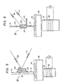
- a first magnetic thin film 31 consisting of a known high permeability film such as e.g. FeNi or CoZr, with film thickness of 0.05 to 0.15 ⁇ m and a width of 5 ⁇ m is placed at right angles to and in close vicinity of a perpendicular magnetic recording medium 35 of e.g. CoCr, TbFe, or CoO. Also this first magnetic thin film 31 is divided into upper and lower parts.
- the permeability of the first magnetic film is preferably 6.3 x 10 ⁇ 4 Hm ⁇ 1 (500) or more, as in Examples 1 to 3.
- a magnetic thin film for optical read-out, i.e. the second magnetic thin film 40 is arranged in close adherence to the first magnetic thin film 31.
- This thin film 40 has, an easy-magnetization axis parallel to the direction in the film surface, and is a magnetic thin film with high magneto-optical conversion efficiency such as e.g. the longitudinal Kerr effect, or the Faraday effect as in Examples 1 to 3.
- a magnetic garnet to begin with Y3Fe5O12 (YIG) a rare earth metal-transition metal system amorphous alloy to begin with GdCo, or an amorphous metal film such as FeCoBP may be used.
- YIG Y3Fe5O12
- a rare earth metal-transition metal system amorphous alloy to begin with GdCo or an amorphous metal film such as FeCoBP
- an auxiliary pole 37 consisting of a soft magnetic material such as e.g. Mn-Zn ferrite, Ni-Zn ferrite, or Co-Zr alloy and a writing coil (excitation coil) 38 are arranged in the reverse side of the medium.
- the arrow 33 denotes the direction of magnetization in the second magnetic thin film 40
- the arrows 34 indicate the magnetic flux
- the arrow in the recording medium 35 indicates the direction of magnetizaation in the medium.
- the substrate 36 of the recording medium is also shown.
- the first magnetic thin film 31 is provided on a non-magnetic substrate such as e.g. glass, but this is omitted from Fig. 5.
- Writing is effected by exciting the auxiliary pole 37 by the coil 38 to magnetize the main pole 30, thereby to induce magnetization of the perpendicular magnetic recording medium 35 directly disposed thereunder.
- Read-out is carried out as follows. At first, the leakage magnetic field from the magnetic domain written in the medium 35 induces the magnetization of the first magnetic thin film 31 of the main pole 30 to order it in one direction. Furthermore, this magnetization also causes the arrangement of the magnetization of the magneto-optical thin film (i.e. the second magnetic thin film 40 attached to the first magnetic thin film 31) into the same direction as that of the first magnetic thin film 31.
- a linearly polarized laser beam 39 When a linearly polarized laser beam 39 is incident obliquely at an angle ⁇ from above the beam reflects on the surface of the magneto-optic thin film (in the case of longitudinal Kerr effect) to become a reflected beam 41 and is passed through a lens optical system and an analyser to be introduced into a photodetector such as e.g. a PIN diode.
- a photodetector such as e.g. a PIN diode.
- the polarized angle of the reflected beam is rotated in proportion to Mscos ⁇ , where Ms is the magnetization of the opto-magnetic thin film. This rotation angle changes sign (anti-clockwise or clockwise rotation) in dependence on the direction of the magnetization (upwards and downwards in the figure).
- the direction of magnetization of the magneto-optic thin film i.e. the second magnetic thin film 40
- the direction of magnetization of the first magnetic thin film 31 and, further, the magnetization state of the medium 35 directly under the main pole can be reproduced according to the present example.
- the direction of magnetization of the magneto-optic thin film is parallel to the film surface, the magnetic flux from the first magnetic thin film can be almost completely introduced into the magneto-optic thin film and the magnetic circuit in the beam irradiated part is closed.
- the magneto-optic reproducing efficiency is extremely high while enabling faithful reproduction for following the magnetization state of the medium.
- the manufacture of the auxiliary pole 37 and the coil 38, are the same as those in the prior art.
- a magneto-optic thin film having an easy-magnetization direction parallel to or in the film surface i.e. the second magnetic thin film 310
- a transparent magnetic material such as Y3Fe5O12
- a reflecting film 42 of an aluminium thin film formed by evaporation may also be provided.
- a secondary reflection film 43 for directing the reflected beam 41 to the upper part of the disc of the recording medium is also provided.
- the loss of flux is small and the flux in the first magnetic thin film 31 is introduced into the magneto-optic thin film, i.e. the second magnetic thin film 310 more efficiently than in the case of Example 4, and a preferable result can be obtained.
- a transparent cover layer for supporting the secondary reflection film 43 is provided, and the secondary reflection film 43 is adhered to the side thereof. Further, symbols in Fig. 6 other than the above are the same as those in Fig. 5.
- the magnetic head of this Example can be manufactured in the same manner as in Example 4 by using a thin film device manufacturing method utilizing known thin film formation methods such as an evaporation method or a sputtering method, and by known thin film patterning methods, e.g. lithography.
- a thin film device manufacturing method utilizing known thin film formation methods such as an evaporation method or a sputtering method, and by known thin film patterning methods, e.g. lithography.
- an auxiliary pole 57 is provided on the same side as the main pole, and a high permeability film 64 (whose magnetization direction is in the surface) is arranged at the lower part of the perpendicular magnetic recording medium 55.
- This planar magnetization film 64 (of e.g. the Fe-Ni alloy called Permalloy) functions when it is at the lower part of the medium, even if it is not provided in the direct low part of the medium.
- the structure circumferentially of the main pole is the same as in Example 5. In this case, the magnetic circuit is perfectly closed through the magneto-optic thin film, i.e. the second magnetic thin film 60 having a magnetization direction parallel to or in the surface, and the reproducing efficiency of the magnetic information from the medium can be made maximum.
- a first magnetic thin film 51 there is also shown a first magnetic thin film 51, a substrate 56 of a magnetic recording medium 55, a coil 58, a linearly polarized laser beam 59, a reflected beam 61, a reflection film 62, and a secondary reflection film 63.
- the arrows in the recording medium indicates the direction of magnetization and the arrows in the other magnetic materials indicate magnetic flux.
- the magnetic head of this Example can also be manufactured by using a known thin film device manufacturing method in the same manner as in Examples 4 and 5.
- the magnetic heads obtained by respective Examples in the above-described Examples 4 to 6 have been improved by about one order in magneto-optic conversion efficiency and reproduction efficiency when compared with the prior art magnetic head shown in Fig. 1.
- the magnetization direction of a thin film having magneto-optic effect is parallel to the film surface, and hence the flux from the high permeability film of the main pole is induced to be approximately completely into the magneto-optic thin film, and the magneto-optic conversion efficiency and the reproduction efficiency are improved Therefore, according to the present invention, the line direction period of a magnetic disc may be of the order of the film thickness of 0.1 ⁇ m of the main pole, and together with that, the track direction period can be made equal to the laser beam diameter (1 to 5 ⁇ m). As a result, the recording density may be improved to a large extent up to the region of 10 bit/ ⁇ m2 which was impossible in the prior art.
Landscapes
- Engineering & Computer Science (AREA)
- Manufacturing & Machinery (AREA)
Claims (8)
- Tête magnétique pour un enregistrement magnétique perpendiculaire et une lecture optique comportant:- un pôle auxiliaire (16);- une bobine d'écriture (13);- un pôle principal possédant une première pellicule mince magnétique (11) de perméabilité élevée et une seconde pellicule mince magnétique (12) présentant un effet magnéto-optique;- un faisceau lumineux tombant sur ladite seconde pellicule mince magnétique;dans laquelle ladite seconde pellicule mince magnétique comporte au moins une partie parallèle à ladite première pellicule mince magnétique et qui, en utilisation, est couplée magnétiquement au champ magnétique de fuite provenant d'un support d'enregistrement magnétique (14);
caractérisée en ce que la seconde pellicule mince magnétique (12) possède un axe de facile aimantation parallèle à ou dans sa surface et, en utilisation, perpendiculaire audit support d'enregistrement (14); et le sens de propagation du faisceau lumineux fait un angle oblique avec la surface de ladite seconde pellicule mince magnétique (12). - Tête magnétique selon la revendication 1, dans laquelle les première et seconde pellicules minces magnétiques (11,12) sont couplées magnétiquement.
- Tête magnétique selon la revendication 1 ou la revendication 2, dans laquelle le pôle principal est une pellicule à double couche comprenant les première et seconde pellicules minces magnétiques (11,12).
- Tête magnétique selon la revendication 1 ou la revendication 2, dans laquelle la première pellicule mince magnétique est divisée en deux parties et la seconde pellicule mince magnétique réunit ces deux parties.
- Tête magnétique selon la revendication 1, dans laquelle les première et seconde pellicules minces magnétiques (11,12) sont stratifiées entre elles par l'intermédiaire d'une pellicule en matériau non magnétique.
- Tête magnétique selon l'une quelconque des revendications 1 à 5, dans laquelle la perméabilité de la première pellicule mince magnétique est au moins 6,3 x 10⁻⁴ T (500).
- Tête magnétique selon l'une quelconque des revendications 1 à 6, dans laquelle l'angle de rotation de la surface de polarisation dû à l'effet magnéto-optique de la seconde pellicule mince magnétique (11) est au moins 0,2°.
- Tête magnétique selon l'une quelconque des revendications précédentes possédant un réflecteur (19) adjacent à la seconde pellicule (12) pour réfléchir vers un détecteur la lumière réfléchie par la seconde pellicule (11).
Applications Claiming Priority (4)
| Application Number | Priority Date | Filing Date | Title |
|---|---|---|---|
| JP5444185A JPS61214264A (ja) | 1985-03-20 | 1985-03-20 | 光磁気ヘツド |
| JP54440/85 | 1985-03-20 | ||
| JP5444085A JPS61214263A (ja) | 1985-03-20 | 1985-03-20 | 光再生磁気ヘツド |
| JP54441/85 | 1985-03-20 |
Publications (3)
| Publication Number | Publication Date |
|---|---|
| EP0195628A2 EP0195628A2 (fr) | 1986-09-24 |
| EP0195628A3 EP0195628A3 (en) | 1988-03-30 |
| EP0195628B1 true EP0195628B1 (fr) | 1991-07-03 |
Family
ID=26395204
Family Applications (1)
| Application Number | Title | Priority Date | Filing Date |
|---|---|---|---|
| EP86301921A Expired EP0195628B1 (fr) | 1985-03-20 | 1986-03-17 | Tête magnétique |
Country Status (3)
| Country | Link |
|---|---|
| US (1) | US4707755A (fr) |
| EP (1) | EP0195628B1 (fr) |
| DE (1) | DE3680010D1 (fr) |
Families Citing this family (7)
| Publication number | Priority date | Publication date | Assignee | Title |
|---|---|---|---|---|
| JPH01287804A (ja) * | 1988-02-15 | 1989-11-20 | Alps Electric Co Ltd | 光磁気記録装置用磁気ヘッド |
| FR2652670B1 (fr) * | 1989-10-03 | 1995-06-23 | Thomson Csf | Tete de lecture magnetooptique a haute resolution. |
| FR2656723B1 (fr) * | 1989-12-28 | 1995-07-21 | Thomson Consumer Electronics | Tete de lecture multipiste magneto-optique. |
| WO1992002931A1 (fr) * | 1990-08-10 | 1992-02-20 | Minnesota Mining And Manufacturing Company | Support d'enregistrement thermomagnetique ayant une haute densite d'enregistrement et une capacite de superposition d'ecriture directe |
| JPH04105235A (ja) * | 1990-08-24 | 1992-04-07 | Sony Corp | 磁気ヘッド |
| US5636187A (en) * | 1992-12-11 | 1997-06-03 | Canon Kabushiki Kaisha | Magnetooptical recording apparatus and magnetooptical recording method for canceling leakage magnetic fields associated with a recording medium and devices ancillary to the recording medium |
| US6188549B1 (en) | 1997-12-10 | 2001-02-13 | Read-Rite Corporation | Magnetoresistive read/write head with high-performance gap layers |
Family Cites Families (4)
| Publication number | Priority date | Publication date | Assignee | Title |
|---|---|---|---|---|
| US3465322A (en) * | 1966-06-20 | 1969-09-02 | Ibm | Transducer utilizing electro-optic effect |
| JPS5459915A (en) * | 1977-10-20 | 1979-05-15 | Sony Corp | Method and apparatus for reading of magnetic recording signal |
| GB2120000B (en) * | 1982-04-28 | 1986-04-09 | Tdk Corp | Magnetic recording and reproduction |
| JPS60143462A (ja) * | 1983-12-29 | 1985-07-29 | Fuji Photo Film Co Ltd | 磁気記録情報再生方法および装置 |
-
1986
- 1986-02-26 US US06/832,884 patent/US4707755A/en not_active Expired - Fee Related
- 1986-03-17 EP EP86301921A patent/EP0195628B1/fr not_active Expired
- 1986-03-17 DE DE8686301921T patent/DE3680010D1/de not_active Expired - Lifetime
Also Published As
| Publication number | Publication date |
|---|---|
| EP0195628A3 (en) | 1988-03-30 |
| US4707755A (en) | 1987-11-17 |
| EP0195628A2 (fr) | 1986-09-24 |
| DE3680010D1 (de) | 1991-08-08 |
Similar Documents
| Publication | Publication Date | Title |
|---|---|---|
| US4701881A (en) | Magneto-optical recording medium | |
| US4628485A (en) | Magneto-optical recording medium | |
| EP0586122B1 (fr) | Dispositif de mémoire magnéto-optique et méthode d'enregistrement et de reproduction d'information | |
| JPS62137754A (ja) | 光磁気再生方法 | |
| US4871614A (en) | Opto-magnetic recording medium having three exchange-coupled magnetic layers | |
| US5265074A (en) | Magneto-optical recording medium | |
| EP0195628B1 (fr) | Tête magnétique | |
| EP0127243A1 (fr) | Dispositif et élément d'enregistrement par voie thermo-magnéto-optique | |
| JPH01237945A (ja) | 光磁気記録媒体 | |
| JP3108397B2 (ja) | 光磁気記録媒体 | |
| JPS5841451A (ja) | 垂直磁気記録体 | |
| US6139980A (en) | Reading method of reading information from a recording medium and medium used therefor | |
| EP0178423A2 (fr) | Milieu d'enregistrement magnéto-optique | |
| US5627803A (en) | Magneto optical recording medium including a plurality of magnetic layers and a method for reducing thereof | |
| JPS6275955A (ja) | 磁気光再生ヘツド | |
| JPS6139956A (ja) | 磁気−光ヘツド | |
| US6120921A (en) | Magneto-optical recording medium | |
| JPS59168954A (ja) | 光磁気記録媒体 | |
| JPS61214264A (ja) | 光磁気ヘツド | |
| JP2000132880A (ja) | 情報再生素子及びそれを備える情報記録/再生ヘッド並びに情報再生方法 | |
| EP1213717A2 (fr) | Support d'enregistrement magnéto-optique | |
| JPS61214263A (ja) | 光再生磁気ヘツド | |
| KR100447159B1 (ko) | 광자기기록매체 | |
| JPS60193147A (ja) | 光熱磁気記録媒体 | |
| KR970010942B1 (ko) | 광자기 기록매체 |
Legal Events
| Date | Code | Title | Description |
|---|---|---|---|
| PUAI | Public reference made under article 153(3) epc to a published international application that has entered the european phase |
Free format text: ORIGINAL CODE: 0009012 |
|
| 17P | Request for examination filed |
Effective date: 19860501 |
|
| AK | Designated contracting states |
Kind code of ref document: A2 Designated state(s): DE FR GB |
|
| PUAL | Search report despatched |
Free format text: ORIGINAL CODE: 0009013 |
|
| AK | Designated contracting states |
Kind code of ref document: A3 Designated state(s): DE FR GB |
|
| 17Q | First examination report despatched |
Effective date: 19891121 |
|
| GRAA | (expected) grant |
Free format text: ORIGINAL CODE: 0009210 |
|
| AK | Designated contracting states |
Kind code of ref document: B1 Designated state(s): DE FR GB |
|
| REF | Corresponds to: |
Ref document number: 3680010 Country of ref document: DE Date of ref document: 19910808 |
|
| ET | Fr: translation filed | ||
| PLBE | No opposition filed within time limit |
Free format text: ORIGINAL CODE: 0009261 |
|
| STAA | Information on the status of an ep patent application or granted ep patent |
Free format text: STATUS: NO OPPOSITION FILED WITHIN TIME LIMIT |
|
| 26N | No opposition filed | ||
| PGFP | Annual fee paid to national office [announced via postgrant information from national office to epo] |
Ref country code: DE Payment date: 19930527 Year of fee payment: 8 |
|
| PGFP | Annual fee paid to national office [announced via postgrant information from national office to epo] |
Ref country code: FR Payment date: 19940217 Year of fee payment: 9 |
|
| PGFP | Annual fee paid to national office [announced via postgrant information from national office to epo] |
Ref country code: GB Payment date: 19940307 Year of fee payment: 9 |
|
| PG25 | Lapsed in a contracting state [announced via postgrant information from national office to epo] |
Ref country code: DE Effective date: 19941201 |
|
| PG25 | Lapsed in a contracting state [announced via postgrant information from national office to epo] |
Ref country code: GB Effective date: 19950317 |
|
| GBPC | Gb: european patent ceased through non-payment of renewal fee |
Effective date: 19950317 |
|
| PG25 | Lapsed in a contracting state [announced via postgrant information from national office to epo] |
Ref country code: FR Free format text: LAPSE BECAUSE OF NON-PAYMENT OF DUE FEES Effective date: 19951130 |
|
| REG | Reference to a national code |
Ref country code: FR Ref legal event code: ST |