EP0195938A2 - Dispositif de mesure de la traction d'un fil, comportant un élément élastique de guidage du fil - Google Patents
Dispositif de mesure de la traction d'un fil, comportant un élément élastique de guidage du fil Download PDFInfo
- Publication number
- EP0195938A2 EP0195938A2 EP86102312A EP86102312A EP0195938A2 EP 0195938 A2 EP0195938 A2 EP 0195938A2 EP 86102312 A EP86102312 A EP 86102312A EP 86102312 A EP86102312 A EP 86102312A EP 0195938 A2 EP0195938 A2 EP 0195938A2
- Authority
- EP
- European Patent Office
- Prior art keywords
- thread
- measuring
- housing
- holder
- thread sensor
- Prior art date
- Legal status (The legal status is an assumption and is not a legal conclusion. Google has not performed a legal analysis and makes no representation as to the accuracy of the status listed.)
- Granted
Links
Images
Classifications
-
- G—PHYSICS
- G01—MEASURING; TESTING
- G01L—MEASURING FORCE, STRESS, TORQUE, WORK, MECHANICAL POWER, MECHANICAL EFFICIENCY, OR FLUID PRESSURE
- G01L5/00—Apparatus for, or methods of, measuring force, work, mechanical power, or torque, specially adapted for specific purposes
- G01L5/04—Apparatus for, or methods of, measuring force, work, mechanical power, or torque, specially adapted for specific purposes for measuring tension in flexible members, e.g. ropes, cables, wires, threads, belts or bands
- G01L5/10—Apparatus for, or methods of, measuring force, work, mechanical power, or torque, specially adapted for specific purposes for measuring tension in flexible members, e.g. ropes, cables, wires, threads, belts or bands using electrical means
- G01L5/105—Apparatus for, or methods of, measuring force, work, mechanical power, or torque, specially adapted for specific purposes for measuring tension in flexible members, e.g. ropes, cables, wires, threads, belts or bands using electrical means using electro-optical means
-
- B—PERFORMING OPERATIONS; TRANSPORTING
- B65—CONVEYING; PACKING; STORING; HANDLING THIN OR FILAMENTARY MATERIAL
- B65H—HANDLING THIN OR FILAMENTARY MATERIAL, e.g. SHEETS, WEBS, CABLES
- B65H59/00—Adjusting or controlling tension in filamentary material, e.g. for preventing snarling; Applications of tension indicators
- B65H59/40—Applications of tension indicators
-
- G—PHYSICS
- G01—MEASURING; TESTING
- G01L—MEASURING FORCE, STRESS, TORQUE, WORK, MECHANICAL POWER, MECHANICAL EFFICIENCY, OR FLUID PRESSURE
- G01L5/00—Apparatus for, or methods of, measuring force, work, mechanical power, or torque, specially adapted for specific purposes
- G01L5/04—Apparatus for, or methods of, measuring force, work, mechanical power, or torque, specially adapted for specific purposes for measuring tension in flexible members, e.g. ropes, cables, wires, threads, belts or bands
- G01L5/042—Apparatus for, or methods of, measuring force, work, mechanical power, or torque, specially adapted for specific purposes for measuring tension in flexible members, e.g. ropes, cables, wires, threads, belts or bands by measuring vibrational characteristics of the flexible member
-
- B—PERFORMING OPERATIONS; TRANSPORTING
- B65—CONVEYING; PACKING; STORING; HANDLING THIN OR FILAMENTARY MATERIAL
- B65H—HANDLING THIN OR FILAMENTARY MATERIAL, e.g. SHEETS, WEBS, CABLES
- B65H2553/00—Sensing or detecting means
- B65H2553/40—Sensing or detecting means using optical, e.g. photographic, elements
- B65H2553/41—Photoelectric detectors
-
- B—PERFORMING OPERATIONS; TRANSPORTING
- B65—CONVEYING; PACKING; STORING; HANDLING THIN OR FILAMENTARY MATERIAL
- B65H—HANDLING THIN OR FILAMENTARY MATERIAL, e.g. SHEETS, WEBS, CABLES
- B65H2601/00—Problem to be solved or advantage achieved
- B65H2601/50—Diminishing, minimizing or reducing
- B65H2601/52—Diminishing, minimizing or reducing entities relating to handling machine
- B65H2601/524—Vibration
-
- B—PERFORMING OPERATIONS; TRANSPORTING
- B65—CONVEYING; PACKING; STORING; HANDLING THIN OR FILAMENTARY MATERIAL
- B65H—HANDLING THIN OR FILAMENTARY MATERIAL, e.g. SHEETS, WEBS, CABLES
- B65H2701/00—Handled material; Storage means
- B65H2701/30—Handled filamentary material
- B65H2701/31—Textiles threads or artificial strands of filaments
Definitions
- the invention relates to a thread tension measuring device with a resiliently movable thread sensor.
- the thread tension is an essential process parameter. Even short-term fluctuations can have a significant influence on the quality of the thread. Therefore, a usable thread tension force meter according to the preamble must have a sufficiently high natural frequency that enables it to follow the frequency of the thread tension fluctuations. This conflicts with the fact that the machine frequencies can lead to vibration excitation of the tensile force meter.
- the invention has for its technical object to provide a tensile force measuring device which follows the thread tension fluctuations with little inertia with a simple and relatively insensitive to disturbances. It is solved by a thread tension measuring device of the type described in the introduction, which is characterized in that the thread sensor is immersed in a magnetic damping fluid to ensure position-independent damping of the thread sensor movements.
- damping piston-shaped extension in the area of the free end of the resiliently movable F adenutelers which extends in the direction of deflection, as damping piston-shaped extension is provided, which dips into a fixed to the holder, filled with a magnetic liquid, which has a magnet, preferably a permanent magnet in the region of its base.
- the extension or damping piston is preferably made of a non-magnetic material.
- an extension which is designed as a damping piston and extends in the deflection direction, is provided, which immerses in a depression, which is fastened to the holder and filled with a magnetic liquid and which has a magnet in the region of its base , preferably has a permanent magnet.
- the extension or damping piston is preferably made of a non-magnetic material.
- Fadenzugkraftmeßvorraum shape of the resiliently movable yarn feeler from a cantilevered P is arallelfeder whose mounting end is fixed to the bracket and whose free, a thread guide exhibiting end carries a formed as a damping piston approach. This is immersed in the magnetic liquid, which is located in a cup-shaped depression attached to the holder.
- a magnet preferably a permanent magnet, is fastened in the region of the pot base, for example either under the pot or in its interior, and holds the magnetic liquid in place regardless of the position.
- the thread sensor is a spring bar which is clamped on one side and which penetrates a damping chamber which is under the action of a magnet and is filled with magnetic damping liquid.
- the thread sensor has a pair of opposite Sidewall an opening that is large enough to allow the spring movement of the thread sensor.
- Another pair of side walls has magnets, under the influence of which the magnetic liquid, which fills the entire interior of the damping chamber, is located.
- the thread sensor is preferably designed as a parallel spring. It is hereby achieved that the free end of the thread sensor only carries out a parallel displacement and therefore the direction of force of the reaction force acting on the thread does not change.
- the elastic deflection of the thread sensor is determined by suitable measuring elements, e.g. Strain gauges determined.
- a largely temperature-independent measuring system consists of a path measuring device through which the path length of the deflection of the thread sensor is measured directly.
- the quantity received being the measurement signal that changes with the size of the deflection.
- a photosensitive cell e.g. Act photodiode.
- a preferred embodiment for all kinds of displacement measurements and in particular yarn feeler with W EC measuring device is suitable, is faced in that an optical transmitter and an optical receiver fixed in the immediate vicinity of the movable end of the resiliently movable yarn sensor are arranged, and that the Thread sensor carries a reflector, e.g. optical prism. It is advantageously provided that the prism angle is slightly different than 90 ° and that the relative distance between the free, resiliently movable end of the thread sensor and the unit of transmitter and receiver is adjustable. This version is very simple Way of "zero adjustment" enables.
- the quantity of reception changes since the reflected rays are not parallel to the transmitted rays.
- the temperature can be adjusted by adjusting the relative distance between the measuring unit and reflector to the desired / calibrated received signal in the unloaded state.
- a special development of the F adenzug- inventive force measuring device may be operable because of their particular configuration, even without a damping device according to the previous description, having a resiliently movable yarn sensor, which is as a cuboid, hollow housing formed with a rectangular or square cross-sectional parallel spring.
- Their side walls which run parallel to the direction of force, that is to say to the direction of action of the thread pulling force on the thread guide, have recesses which have a bone shape and are symmetrical to the bending plane of the plane lying in the longitudinal axis of the housing and perpendicular to the direction of force and extending over a considerable part of the housing length.
- “Bone shape” is understood to mean openings in the side walls that have parallel boundaries and end in circular extensions at both ends.
- a rigid measuring rod is clamped together with the clamping end of the housing, which protrudes into the housing essentially up to the area of its free end.
- the free end of the housing forming the thread sensor has a thread guide as an extension running essentially in the housing axis and a measuring head inside in close proximity to the free end of the rigid measuring rod.
- the dipstick is preferably made of the same for temperature compensation Material made like the cuboid housing.
- the top and bottom of the housing also have recesses or cutouts in order to adapt the spring characteristic and thus the measurement deflection of the housing to the thread tension to be expected.
- the head piece of the cuboid housing has a projection in the direction of force, designed as a damping piston, which dips into the magnetic liquid in a pot-shaped depression fastened to the holder, which in turn is on a magnet, preferably a permanent magnet. sits or has one at the bottom of its interior. It may be advantageous to also manufacture the cup-shaped depression containing the magnetic liquid from a material with non-magnetic properties.
- a thread tension measuring device is created with which high-frequency thread tension fluctuations of e.g. 30 to 40 Hz are measurable. It is still possible to extend the measuring range by using a measuring amplifier whose characteristic curve rises in the range of the natural frequency of the spring-movable thread sensor and thereby completely or partially compensates for the frequency-dependent characteristic curve of the thread sensor.
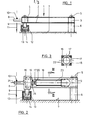
- the thread sensor 1 of F ig. 1 consists of two identical narrow leaf springs 2, which are assembled by means of the intermediate piece 4 at the free end and the fastening piece 3 at the clamping end to form the parallel spring 2-4.
- the fastening end 3 of the parallel spring 2-4 is firmly connected to the holder 7, which can also be the machine frame, by means of a screw connection 5.
- the free end (intermediate piece 4) has a thread guide 8 and an extension or damping piston 9 extending in the force direction 11, ie the direction of action of the thread pulling force on the thread guide 8.
- the thread 10 engaging the thread guide 8 can, for example, also be guided in a thread guide bore in the thread guide 8.
- Magnetic liquids are also called “ferrofluids” in the literature. This is a dispersion of extremely tiny magnetic material particles, for example Fe 3 0 4 . These particles are finely distributed in liquids such as kerosene or silicone oils. Magnetic liquids are manufactured, for example, by Ferrofluidics GmbH, Nürtingen, BR Germany. Further information can be found, for example, in US Pat. No. 4,107,063 and in the article “Magnetic-fluid seals" in "Laser Focus Magazine", April 1979, pp. 56-63, Advanced Technology Publications, 1001 Watertown St., Newton, MA 02165 .
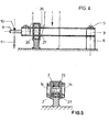
- FIGS. 2 and 3 Another advantageous embodiment of the invention is shown in FIGS. 2 and 3, FIG. 3 being a section along III-III in FIG. 2.
- the spring constant can be relatively large.
- the natural frequency is relatively high. Consequently, high-frequency fluctuations in thread tension can still be detected.
- a device according to the invention for damping vibrations 9, 12-14 is arranged, fluctuations in thread tension with frequencies in the range of approximately 50 Hz can be registered if a correspondingly inertia-free device such as electro-optical scanning is used.
- By compensating the frequency response of the sensor by means of an amplifier with frequency response compensation, tensile force frequencies of several 100 Hertz can be recorded.
- the illustrated embodiment consists of a cuboid housing 16 made from a tube with a square cross section, the cross section of which is shown along III-III in FIG. 2 in FIG. 3. Its fastening end 3 is connected by means of the screws 5 to the holder 7 via an intermediate piece 6, while the front, free end carries a head piece 15 with the thread guide 8 and a shoulder or damping piston 9 pointing in the direction of force (arrow 11).
- "bone-shaped" recesses 17 are provided which extend over a large part of the length of the housing. They have parallel boundary edges and end in circular extensions, the diameter of which corresponds to the inner cross-sectional dimension of the housing 16.
- the damping piston 9 is immersed in the pot 12 filled with magnetic liquid 13, so that the vibrations excited by the machine are damped.
- the tensile force measuring device of the invention becomes position-independent by means of the magnetic liquid 13 stabilized in the recess 12 (pot 12) with the aid of the magnet 14, which is preferably a permanent magnet.
- a rigid measuring rod 23 projects with its measuring insert 20 into the region of the free housing end (head piece 15).
- a measuring head 19 with holder 24 is fastened in the free end or inside the head piece 15, which together with the free housing end 15 or the thread guide 8 can participate in the movements caused by the thread tension.
- the measuring rod 23 with its measuring head 20 is then rigidly fixed between the two leaf springs 2 in the clamping end 3, while the measuring head 19 with its holder 24 is accommodated in the intermediate piece 4.
- Other, for example pneumatic, scanning devices can also be used in the two embodiments described.
- Damping pistons or extension 9 and recess or pot 12 made of a non-magnetic material are advantageous.
- the intermediate pieces 3, 4 of the parallel spring are advantageous 2-4 as well as the housing 16 and the holder 24 and the dipstick 23 made of the same material.
- the damping device according to the invention can be used successfully in all thread tension measuring devices with tapping of the relative movement between a thread sensor moved by the thread pull force relative to its holder and the holder for suppressing measurement errors caused by natural vibration phenomena of the thread sensors.
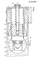
- the leaf springs 2 penetrate the damping chamber 25.
- the leaf springs are clamped in place at their clamping end 3 by means of spacers 6 and screw 5.
- the thread 10 lies on the thread guide 8.
- the thread guide 8 is attached to the free end 4.
- displacement measuring devices or, above all, strain gauges on the leaf springs can be used.
- the damping chamber 25 is closed on all sides except for the openings 26 and 27. These openings enclose the cross section of the leaf springs 2 as closely as possible, but in such a way that the spring movement is permitted unhindered.
- the damping chamber is completely filled with a magnetic liquid.
- the permanent magnets 14 are arranged on both sides of the damping chamber.
- the measuring head 19 carries a prism 28.
- the angle alpha of this prism is slightly less than 90 °.
- the measuring head 20 carries a radiation source 29 on the one hand and a receiver 30 on the other hand.
- the radiation source can be, for example, a light source and the receiver a photodiode 31. Since the angle alpha is not equal to 90 °, the emitted light beams are not reflected in parallel. Therefore, the reflected rays hit only at a predetermined distance A between the measuring heads 19 and 20 in the Center of the photodiode 31 for generating the optimal measurement deflection of the measurement voltage U.
- This measurement deflection is specified as a calibration signal of the unloaded state of the thread sensor. If the distance A now changes as a result of temperature fluctuations and corresponding expansion of the housing 16 on the one hand and the measuring rod 23 on the other hand, a changed calibration signal U also results at zero load. The temperature adjustment is made in that the measuring rod 23 in its guide 32 is shifted until the calibration signal U reappears. For this purpose, the measuring rod 23 is slidably guided in the holder as an exemplary embodiment. To adjust the dipstick, an adjusting screw 33 is provided in the holder 32. This set screw 33 is rotatably mounted in the holder and engages with a thread in the dipstick 23. The back of the dipstick 23 is supported on the bracket 32 by compression spring 34.
Landscapes
- Physics & Mathematics (AREA)
- General Physics & Mathematics (AREA)
- Force Measurement Appropriate To Specific Purposes (AREA)
- Treatment Of Fiber Materials (AREA)
Applications Claiming Priority (4)
| Application Number | Priority Date | Filing Date | Title |
|---|---|---|---|
| DE3506897 | 1985-02-27 | ||
| DE3506897 | 1985-02-27 | ||
| DE3522239 | 1985-06-21 | ||
| DE3522239 | 1985-06-21 |
Publications (3)
| Publication Number | Publication Date |
|---|---|
| EP0195938A2 true EP0195938A2 (fr) | 1986-10-01 |
| EP0195938A3 EP0195938A3 (en) | 1987-09-23 |
| EP0195938B1 EP0195938B1 (fr) | 1989-08-02 |
Family
ID=25829803
Family Applications (1)
| Application Number | Title | Priority Date | Filing Date |
|---|---|---|---|
| EP86102312A Expired EP0195938B1 (fr) | 1985-02-27 | 1986-02-22 | Dispositif de mesure de la traction d'un fil, comportant un élément élastique de guidage du fil |
Country Status (4)
| Country | Link |
|---|---|
| US (1) | US4677860A (fr) |
| EP (1) | EP0195938B1 (fr) |
| CN (1) | CN1014830B (fr) |
| DE (1) | DE3664815D1 (fr) |
Cited By (3)
| Publication number | Priority date | Publication date | Assignee | Title |
|---|---|---|---|---|
| EP0299738B1 (fr) * | 1987-07-14 | 1992-06-17 | E.I. Du Pont De Nemours And Company | Dispositif de mesure de tension |
| US5329822A (en) * | 1991-09-07 | 1994-07-19 | W. Schlafhorst Ag & Co. | Yarn tension sensor for a textile machine |
| DE4400037A1 (de) * | 1994-01-04 | 1995-07-06 | Wolfgang Dr Schaefer | Winkelmeßeinrichtung, insbesondere für Fadenzugkraftaufnehmer |
Families Citing this family (12)
| Publication number | Priority date | Publication date | Assignee | Title |
|---|---|---|---|---|
| US4766758A (en) * | 1987-04-27 | 1988-08-30 | Helm Instrument Co., Inc. | Method of measuring strain forces in a press |
| US5270951A (en) * | 1990-05-22 | 1993-12-14 | Barmag Ag | Method and apparatus for storing error signals |
| DE19614027A1 (de) * | 1996-04-09 | 1998-01-22 | Inst Textil & Faserforschung | Verfahren zum Nachweis von untexturierten Garnabschnitten in texturierten Filamentgarnen mittels Bestimmung hochfrequenter Fadenzugkraftsschwankungen |
| EP0852217A3 (fr) * | 1997-01-03 | 1998-11-25 | New House Textiles Limited | Dispositif de contrÔle de la tension |
| DE10259727A1 (de) * | 2002-12-19 | 2004-07-08 | Iropa Ag | Tensiometer |
| GB0323906D0 (en) * | 2003-10-11 | 2003-11-12 | Bandara Palitha | Instrument for measuring the tension in a textile yarn using non-contact sensing |
| JP4886324B2 (ja) * | 2006-03-02 | 2012-02-29 | 出光興産株式会社 | 第2級ブタノール製造用反応器 |
| JP4931069B2 (ja) * | 2007-06-08 | 2012-05-16 | 株式会社豊田中央研究所 | 糸張力検出器及びジェットルームにおける緯糸張力検出装置 |
| JP5541759B2 (ja) * | 2012-05-08 | 2014-07-09 | 株式会社原子力エンジニアリング | ひずみゲージホルダー |
| CN104019929B (zh) * | 2014-06-11 | 2016-02-03 | 中国船舶重工集团公司第七0四研究所 | 基于电涡流相对位移测量的转轴扭矩在线测试方法 |
| WO2017183163A1 (fr) * | 2016-04-21 | 2017-10-26 | 三菱電機株式会社 | Détecteur de charge et détecteur de tension |
| CN108675053A (zh) * | 2018-05-22 | 2018-10-19 | 泉州永春中大机械技术有限公司 | 一种电缆线张力调整机构用可控式调整器 |
Family Cites Families (20)
| Publication number | Priority date | Publication date | Assignee | Title |
|---|---|---|---|---|
| DE133079C (fr) * | ||||
| US2159969A (en) * | 1937-01-12 | 1939-05-30 | Schlafhorst & Co W | Appliance for testing the tension of textile threads or yarn |
| US2383537A (en) * | 1943-09-09 | 1945-08-28 | Celanese Corp | Tension indicator |
| US2407545A (en) * | 1944-01-13 | 1946-09-10 | Fish Joseph Raymond | Thread friction testing device |
| GB782015A (en) * | 1954-01-22 | 1957-08-28 | British Celanese | Improvements in or relating to tension control |
| US2809519A (en) * | 1954-09-22 | 1957-10-15 | Olin Mathieson | Web flatness indicator |
| US3005332A (en) * | 1959-03-17 | 1961-10-24 | Mcclintock Ralph Michael | Strain gage calibration device |
| US3206972A (en) * | 1962-09-27 | 1965-09-21 | Armco Steel Corp | Furnace tensiometer |
| US3376738A (en) * | 1965-06-28 | 1968-04-09 | Exxon Production Research Co | Automatic refill and temperature compensation device for hydraulic systems |
| US3498553A (en) * | 1968-03-15 | 1970-03-03 | Leesona Corp | Wire tensioning device |
| GB1330592A (en) * | 1971-06-30 | 1973-09-19 | Metal Detection Ltd | Belt weighing apparatus |
| SU398843A1 (ru) * | 1972-01-11 | 1973-09-27 | Измеритель натяжения ленты | |
| US3771346A (en) * | 1972-06-21 | 1973-11-13 | Moore Products Co | Calibrating devices |
| CA1075095A (fr) * | 1973-09-11 | 1980-04-08 | Lucien N. Larue | Dispositif et methode pour deceler la tension excessive et prolongee des files de textile |
| US3880001A (en) * | 1974-03-25 | 1975-04-29 | Du Pont | Yarn tension or break monitoring apparatus |
| SU609988A1 (ru) * | 1975-10-28 | 1978-06-05 | Подольский Ордена Ленина И Ордена Трудового Красного Знамени Механический Завод Им.М.И.Калинина | Устройство дл измерени нат жени нити |
| US4091885A (en) * | 1976-08-30 | 1978-05-30 | Advance Weight Systems, Inc. | Weight sensing apparatus |
| FR2405202A1 (fr) * | 1977-10-06 | 1979-05-04 | Inst Textile De France | Procede et capteur de tension d'une nappe de fils en defilement |
| GB2025055A (en) * | 1978-07-08 | 1980-01-16 | Auto Egg Ltd | Weighing Apparatus |
| US4182167A (en) * | 1978-09-07 | 1980-01-08 | Toray Industries, Inc. | Yarn tension meter |
-
1986
- 1986-01-20 CN CN86100336A patent/CN1014830B/zh not_active Expired
- 1986-02-22 DE DE8686102312T patent/DE3664815D1/de not_active Expired
- 1986-02-22 EP EP86102312A patent/EP0195938B1/fr not_active Expired
- 1986-02-26 US US06/833,906 patent/US4677860A/en not_active Expired - Fee Related
Cited By (4)
| Publication number | Priority date | Publication date | Assignee | Title |
|---|---|---|---|---|
| EP0299738B1 (fr) * | 1987-07-14 | 1992-06-17 | E.I. Du Pont De Nemours And Company | Dispositif de mesure de tension |
| US5329822A (en) * | 1991-09-07 | 1994-07-19 | W. Schlafhorst Ag & Co. | Yarn tension sensor for a textile machine |
| DE4400037A1 (de) * | 1994-01-04 | 1995-07-06 | Wolfgang Dr Schaefer | Winkelmeßeinrichtung, insbesondere für Fadenzugkraftaufnehmer |
| DE4400037C2 (de) * | 1994-01-04 | 2002-12-12 | Wolfgang Schaefer | Winkelmeßeinrichtung, insbesondere für Fadenzugkraftaufnehmer |
Also Published As
| Publication number | Publication date |
|---|---|
| EP0195938B1 (fr) | 1989-08-02 |
| EP0195938A3 (en) | 1987-09-23 |
| DE3664815D1 (en) | 1989-09-07 |
| CN1014830B (zh) | 1991-11-20 |
| US4677860A (en) | 1987-07-07 |
| CN86100336A (zh) | 1987-01-07 |
Similar Documents
| Publication | Publication Date | Title |
|---|---|---|
| EP0195938A2 (fr) | Dispositif de mesure de la traction d'un fil, comportant un élément élastique de guidage du fil | |
| DE2553638C2 (de) | Vorrichtung zur Messung von Massen | |
| DE3877913T2 (de) | Vibrationsrheometer. | |
| EP0391130A1 (fr) | Dispositif pour l'amortissement actif d'oscillations | |
| EP0100429A2 (fr) | Transducteur de mesure | |
| DE19922102B4 (de) | Faser-Bragg-Gitter-Sensoranordnung zur Ermittlung physikalischer Größen | |
| DE3118607C2 (de) | Längenmeßgerät | |
| DE3334911A1 (de) | Zweiachsen-linearmotor | |
| EP0209515A1 (fr) | Détecteur à fibre optique | |
| EP0028302B1 (fr) | Capteur différentiel de champ magnétique | |
| DE2712890A1 (de) | Beschleunigungsaufnehmer | |
| DE2246500C2 (de) | Kraft- oder Längenmessgerät | |
| DE2840630C3 (de) | Vorrichtung zur Messung der Zugfestigkeit und/oder der Dehnung eines bahnförmigen Meßobjektes | |
| DD255784A1 (de) | Koordinatentastkopf mit einrichtung zur messkraftstabilisierung fuer koordinatenmessgeraete | |
| DE8505607U1 (de) | Fadenzugkraftmeßvorrichtung mit federnd bewegbarem Fadenfühler | |
| DE4041142A1 (de) | Vorrichtung zur ermittlung der fadenspannung | |
| EP0036532A1 (fr) | Transmetteur pour la mesure des forces mécaniques | |
| DE3818515C1 (en) | Method and device for testing the pretensiong force on traction means | |
| DE1238564B (de) | OEldaempfung fuer schnellschwingende Galvano-meter | |
| DE3737461C2 (de) | Führungsvorrichtung für einen Prüfkörper eines Härtemeßgerätes | |
| CH366979A (de) | Längen-Messeinrichtung, insbesondere zum Abgleich von Werkstücken | |
| DE19845732A1 (de) | Zugprüfmaschine | |
| DE3039730A1 (de) | Linear-messlehre | |
| DE1292767B (de) | Justiervorrichtung fuer optische Sender oder Verstaerker | |
| DE3608392C2 (fr) |
Legal Events
| Date | Code | Title | Description |
|---|---|---|---|
| PUAI | Public reference made under article 153(3) epc to a published international application that has entered the european phase |
Free format text: ORIGINAL CODE: 0009012 |
|
| AK | Designated contracting states |
Kind code of ref document: A2 Designated state(s): CH DE FR GB IT LI |
|
| RAP1 | Party data changed (applicant data changed or rights of an application transferred) |
Owner name: B A R M A G AG |
|
| PUAL | Search report despatched |
Free format text: ORIGINAL CODE: 0009013 |
|
| AK | Designated contracting states |
Kind code of ref document: A3 Designated state(s): CH DE FR GB IT LI |
|
| 17P | Request for examination filed |
Effective date: 19870923 |
|
| 17Q | First examination report despatched |
Effective date: 19880819 |
|
| ITF | It: translation for a ep patent filed | ||
| GRAA | (expected) grant |
Free format text: ORIGINAL CODE: 0009210 |
|
| AK | Designated contracting states |
Kind code of ref document: B1 Designated state(s): CH DE FR GB IT LI |
|
| REF | Corresponds to: |
Ref document number: 3664815 Country of ref document: DE Date of ref document: 19890907 |
|
| ET | Fr: translation filed | ||
| GBT | Gb: translation of ep patent filed (gb section 77(6)(a)/1977) | ||
| PGFP | Annual fee paid to national office [announced via postgrant information from national office to epo] |
Ref country code: FR Payment date: 19900119 Year of fee payment: 5 |
|
| PGFP | Annual fee paid to national office [announced via postgrant information from national office to epo] |
Ref country code: CH Payment date: 19900219 Year of fee payment: 5 |
|
| PGFP | Annual fee paid to national office [announced via postgrant information from national office to epo] |
Ref country code: DE Payment date: 19900221 Year of fee payment: 5 |
|
| ITTA | It: last paid annual fee | ||
| PGFP | Annual fee paid to national office [announced via postgrant information from national office to epo] |
Ref country code: GB Payment date: 19900228 Year of fee payment: 5 |
|
| PLBE | No opposition filed within time limit |
Free format text: ORIGINAL CODE: 0009261 |
|
| STAA | Information on the status of an ep patent application or granted ep patent |
Free format text: STATUS: NO OPPOSITION FILED WITHIN TIME LIMIT |
|
| 26N | No opposition filed | ||
| PG25 | Lapsed in a contracting state [announced via postgrant information from national office to epo] |
Ref country code: GB Effective date: 19910222 |
|
| PG25 | Lapsed in a contracting state [announced via postgrant information from national office to epo] |
Ref country code: LI Effective date: 19910228 Ref country code: CH Effective date: 19910228 |
|
| GBPC | Gb: european patent ceased through non-payment of renewal fee | ||
| PG25 | Lapsed in a contracting state [announced via postgrant information from national office to epo] |
Ref country code: FR Effective date: 19911031 |
|
| REG | Reference to a national code |
Ref country code: CH Ref legal event code: PL |
|
| PG25 | Lapsed in a contracting state [announced via postgrant information from national office to epo] |
Ref country code: DE Effective date: 19911101 |
|
| REG | Reference to a national code |
Ref country code: FR Ref legal event code: ST |
|
| PG25 | Lapsed in a contracting state [announced via postgrant information from national office to epo] |
Ref country code: IT Free format text: LAPSE BECAUSE OF NON-PAYMENT OF DUE FEES;WARNING: LAPSES OF ITALIAN PATENTS WITH EFFECTIVE DATE BEFORE 2007 MAY HAVE OCCURRED AT ANY TIME BEFORE 2007. THE CORRECT EFFECTIVE DATE MAY BE DIFFERENT FROM THE ONE RECORDED. Effective date: 20050222 |