EP0196086A2 - Spulenmontage für eine elektrische Drehmaschine - Google Patents
Spulenmontage für eine elektrische Drehmaschine Download PDFInfo
- Publication number
- EP0196086A2 EP0196086A2 EP86104156A EP86104156A EP0196086A2 EP 0196086 A2 EP0196086 A2 EP 0196086A2 EP 86104156 A EP86104156 A EP 86104156A EP 86104156 A EP86104156 A EP 86104156A EP 0196086 A2 EP0196086 A2 EP 0196086A2
- Authority
- EP
- European Patent Office
- Prior art keywords
- coil
- conductors
- coil assembly
- armature coil
- assembly according
- Prior art date
- Legal status (The legal status is an assumption and is not a legal conclusion. Google has not performed a legal analysis and makes no representation as to the accuracy of the status listed.)
- Granted
Links
Images


Classifications
-
- H—ELECTRICITY
- H02—GENERATION; CONVERSION OR DISTRIBUTION OF ELECTRIC POWER
- H02K—DYNAMO-ELECTRIC MACHINES
- H02K3/00—Details of windings
- H02K3/04—Windings characterised by the conductor shape, form or construction, e.g. with bar conductors
- H02K3/26—Windings characterised by the conductor shape, form or construction, e.g. with bar conductors consisting of printed conductors
-
- H—ELECTRICITY
- H02—GENERATION; CONVERSION OR DISTRIBUTION OF ELECTRIC POWER
- H02K—DYNAMO-ELECTRIC MACHINES
- H02K19/00—Synchronous motors or generators
- H02K19/16—Synchronous generators
- H02K19/22—Synchronous generators having windings each turn of which co-operates alternately with poles of opposite polarity, e.g. heteropolar generators
-
- H—ELECTRICITY
- H02—GENERATION; CONVERSION OR DISTRIBUTION OF ELECTRIC POWER
- H02K—DYNAMO-ELECTRIC MACHINES
- H02K21/00—Synchronous motors having permanent magnets; Synchronous generators having permanent magnets
- H02K21/12—Synchronous motors having permanent magnets; Synchronous generators having permanent magnets with stationary armatures and rotating magnets
- H02K21/24—Synchronous motors having permanent magnets; Synchronous generators having permanent magnets with stationary armatures and rotating magnets with magnets axially facing the armatures, e.g. hub-type cycle dynamos
Definitions
- the present invention relates to coil assemblies used for rotary electric machines such as magnet generator or magnet motor.
- a conventional armature coil of this type as disclosed in the specification of U.S. Patent No. 3091715, comprises tabular half-coil conductors each including an inner portion, outer portion inclined radially and radial central portion provided by printed wiring on both sides of an insulating disc.
- a radial recess or slot is formed in the central portion of the half coil to divide each conductor into two branches, and a tongue of magnetic material is put to fill the recess thereby to increase the effective magnetic fluxes in the gap'.
- the conductor is tabular in form and occupies a certain width in peripheral direction when arranged on the insulated disc, it is impossible to increase a number of winding turns, and therefore an output more than a predetermined level cannot be produced.
- an armature coil comprising a multiplicity of flat conductors extending along radial direction and arranged substantially at equal intervals peripherally through gaps, and a plurality of ferromagnetic members inserted between the conductors.
- the inserted ferromagnetic members provide a magnetic anisotropy in the armature coil in the direction of the rotational axis of the coil, so that the flow of magnetic fluxes from the magnetic poles toward the core of the rotary machine thereby to reduce the leakage magnetic fluxes.
- Another object of the present invention is to provide an armature coil using a multiplicity of flat V-shaped conductors prepared by pressing conductor plates.
- stator coil assembly comprising like conductors arranged along an insulating cylindrical support.
- Still another object of the present invention is to provide a flat-type rotary electric machine comprising an armature coil including a multiplicity of flat conductors arranged at substantially equal peripheral intervals through gaps and ferromagnetic members inserted in the gaps, magnetic poles arranged on the axial ends of these conductors, and a core member for passing the magnetic fluxes generated from the magnetic poles across the conductors.
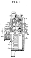
- a three-phase AC coil 1 of a magnet generator includes flat coil segment or pieces 3 making up conductors radially extending along the diameter on the front and back side of an annular heat conductive insulating plate 2 having a hollow portion 2a at the central part thereof.
- a coil piece 3 which is made of a non-magnetic copper plate, is arranged on the insulating plate 2 in such a manner as to have the width thereof along the axial direction.
- a multiplicity of coil pieces 3 are arranged equidistantly through gaps 4 along the peripheral direction.
- the outer and inner peripheries of the coil piece 3 are welded on both the front and back thereby to obtain a three-phase AC coil 1 in flat wave-winding form.
- a method of fabrication of this three-phase AC coil 1 is disclosed in the specification of.U.S. Patent No. 4500806.
- the front and back side gaps 4 on the plate 2 of the three-phase AC coil 1 are filled with an epoxy resin 5 mixed with a ferromagnetic material (such as ferrite, nickel or iron at least 10 in specific magnetic permeability).
- a ferromagnetic material such as ferrite, nickel or iron at least 10 in specific magnetic permeability.
- the epoxy resin 5 is inserted along the axial direction (by the thickness of the coil piece 3) in the gaps 4.
- heat is applied to thermally set the epoxy resin 5.
- the coil pieces 3 are fixed to form the three-phase AC coil 1.
- Holders 7 and 8 with a channel or U-shaped section are arranged through a heat conductive insulating sheet 6 on the outer and inner peripheral sides of the three-phase AC coil 1.
- These holders 7 and 8 are made of a material of high heat conductivity such as aluminum, and insulates a rear housing 9 and the coil pieces of the three-phase AC coil 1 from each other by means of the heat conductive insulating sheet 6.
- the rear housing 9 formed of aluminum includes a flat portion 9a covering the end face of the three-phase coil 1, a first holder section 9b defining the outer periphery of the holder 7 formed on the outer periphery of the flat portion 9a, and a second holder section 9c formed on the inner side of the flat portion 9a for defining the outer periphery of the holder 8.
- the three-phase AC coil 1 having the holders 7 and 8 mounted thereon is fixed between the first holder section 9b and the second holder section 9c.
- the inner side of the second holder section 9c is formed with a recess 9d into which a shaft 11 is inserted with a bearing 16 therebetween.
- the outer periphery of the flat portion 9a is formed with a fin 9e to secure heat radiation.
- a flat iron core 11 of magnetic material such as a ferromagnetic iron is arranged with a heat conductive insulating plate 10 between the three-phase AC coil 1 and the flat portion 9a of the rear housing 9.
- the front housing 12 is also formed of aluminum, and the three-phase AC coil 1 is securely held between the front housing 12 and the rear housing 9.
- Two openings including first and second openings 12a and 12b are formed in the axial ends of the front housing 12, and a plurality of exhaust holes 12c are formed on the outer periphery along the diametrical direction.
- a partition wall 12d is provided between the first and second openings 12a and 12b.
- the step 12e of the front housing 12 is connected by spigot joint with the first holder section 9b of the rear housing 9, so that the housing 9 and the housing 12 are integrally fixed by a through bolt not shown.
- a screw 19 is used to secure a bearing 16 with a bracket 20 fixed on the inner side of the front housing 12.
- a shaft 13 having a pulley 14 fixed to an end thereof with a bolt 15 is rotatably supported on the front housing 12 and the rear housing 9 through the bearings 16.
- the outer periphery of this shaft 13 has a rotor 17 fixed thereto, which rotor 17 is adapted to rotate integrally with the shaft 13.
- the rotor 17 is provided with a permanent magnet 18 forming a field at a position opposite to the iron core 11 through the three-phase AC coil 1 as shown in Fig. 3.
- This permanent magnet 18 is magnetized in axial direction.
- a plurality of such permanent magnet 18 have magnetic poles alternating in polarity and arranged along the circumferential direction.
- the permanent magnet 18 may alternatively be magnetized in the circumferential direction instead of the axial direction.
- a plurality of coil pieces 3 are arranged over the peripheral width of the permanent magnet 18.
- a plurality of scoops 17a and fans 17b are formed at positions opposing to the first and second openings 12a and 12b respectively along the periphery on the front housing 12 side of the rotor 17.
- a hole 17c is provided at the positions of the scoops 17a.
- a thyristor 21 is electrically connected to the three-phase AC coil 1 and is securely fitted by screw to the inner periphery of the front housing 12.
- An output terminal 22 is electrically connected to a thyristor bridge including the thyristor 21 and a diode not shown.
- the rotor 17 rotates with the shaft 13.
- the rotation of the fans 17b of the rotor 17 causes the air from the first opening 12a to cool the thyristor bridge 21 and to flow out through the exhaust ports 12c.
- the scoops 17a causes the air from the second opening 12b to cool the three-phase AC coil 1 through the hole 17c and flow out through the exhaust ports 12c in similar manner.
- Fig. 3 is an enlarged sectional view taken along the line (A)-(A) in Fig. 1, and shows a case in which the magnetic fluxes of the magnet 18 act on the three-phase AC coil 1.
- the quantity of magnetic fluxes involved is shown in Table 1 below.
- character A designates the center of the magnet 18 which corresponds substantially to the center of a coil piece 3 on the back side (the rear housing 9 side) of the insulating plate 2
- character B designates the center of the magnet 18 which corresponds substantially to the center of a coil piece 3 of the front side (front housing 12 side) of the insulating plate 12
- character C designates the center between the adjacent magnets 18 and corresponds substantially to the center of a coil piece 3 on the back side (rear housing 9 side) of the insulating plate 2
- character D designates the center between the adjacent magnets 18 and corresponds substantially to the center of a coil piece 3 on the front side (front housing 12 side) of the insulating plate 2.
- character X designates the quantity of magnetic fluxes (in Gauss) flowing from the magnet 18 toward the iron core 11 in parallel
- character Y designates the quantity of magnetic fluxes (in Gauss) flowing in vertical direction (upward) of the iron core 11 from the magnet 18.
- Fig. 8 shows a conventional construction in which there is not any ferromagnetic material inserted in the gaps between the coil pieces 3 of the three-phase AC coil 1.
- Table 2 indicates a distribution of magnetic fluxes of the three-phase AC coil 1 shown in Fig. 8.
- the three-phase AC coil 1 is subjected to an axial magnetic anisotropy, thereby making it possible to apply the magnetic fluxes of the magnet 18 effectively to the iron core 11.
- the output of the magnet generator is improved with the same volume or geometrical features.
- the three-phase AC coil 1 is securely held between the first holder section 91 and the second holder section 9b thereby to prevent the three-phase AC coil 1 from vibrating in high-speed operating range.
- the coil piece 3 which is thin in the direction opposed to the magnet 18 and thick in axial direction (in which the magnetic fluxes flow), hardly develops an eddy current.
- the ampere turn is much increased.
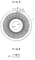
- ferromagnetic members are inserted in alternate gaps 4 between the coil pieces 3.
- Each of the ferromagnetic members is made of an iron plate 23 with the surface thereof insulation-treated as shown in Fig. 5. This iron plate 23 is inserted in the alternate gaps 4. Subsequently, an adhesive 24 is injected into the rest gaps 4 thereby to secure the coil piece 3 and the iron plates 23 in the gaps 4 at the same time.
- Fig. 6 shows a distribution of magnetic fluxes of the magnet 18, and Table 3 shows the quantity of magnetic fluxes.
- Table 3 indicates that as compared with the case shown in Table 1 related to the first embodiment, the magnetic fluxes flowing in axial direction in the iron core 11 from the magnet 18 are increased, thus making it possible to apply the magnetic fluxes of the magnet 18 more effectively to the iron core 11.
- characters E, F and G designate the characteristic for the specific magnetic permeability (us) of 1 (without any ferromagnetic member), 500 and 5000 respectively, however, indicates that with the increase in the specific magnetic permeability of the ferromagnetic member, the input is increased in the low- speed area, and the input is saturated with the increase in the coil impedance in the high speed area.
- the input characteristic which is changed by the change in winding specification in the prior art, can be changed merely by changing the specific magnetic permeability of a ferromagnetic member according to the present invention.
- a thermosetting resin, or a silicon-varnish mixture disclosed in the Japanese Patent Publication Laid-Open No. 51-82319 may be employed.
- the present invention may be applied, instead of to a three-phase AC coil 1 of a magnet generator, to a DC rotary electric machine with an armature of a printed circuit comprising a multiplicity of tabular conductors arranged on the front and back sides of an insulating plate and their inner and outer peripheries connected as disclosed in the U.S. Patent No. 3231774. Further, as indicated by the U.S. Patent No. 3480815, the present invention may be used with a motor or the like having a disc-like armature with a multiplicity of coils in wave winding.
- the permanent magnet 18 may be replaced with equal effect by iron core wound with a coil to generate a magnetic a field.
- a permanent magnet may be used in place of the iron core 11 making up a magnetic member.
- FIG. 9 A third embodiment is shown in Figs. 9 to 11, Fig. 9 illustrating a perspective view of a coil piece 3, and Fig. 10 a front view of the coil piece 3.
- This coil piece 3 is formed of a single plate subjected to press work, in which an upper arm 3a and a lower arm 3b are formed branching out from the center to define a V-shape.
- a predetermined gap is formed in the pressing work so as to accomodate the insulating plate 2 between the upper arm 3a and the lower arm 3b.
- a couple of iron plates 30 having a substantially equal thickness along the periphery and axis are welded or otherwise connected in the parallel peripheral direction at the parts of the upper arm 3a and the lower arm 3b which are opposed to the magnet 18.
- the parts of the upper arm 3a and the lower arm 3b opposing to the magnet 18 are smaller in axial thickness than the ends thereby to reduce the resistance thereat.
- the center of the coil piece 3 is inserted from the central hole 2a side of the insulating plate 2, and the insulating plate 2 is inserted between the upper arm 3a and the lower arm 3b.
- the upper arm 3a of another coil piece 3 is disposed on the lower arm 3b of the first-inserted coil piece 3 by way of the insulating plate 2.
- peripheral end portions 3a' and 3b' of the upper arm 3a and the lower arm 3b of the coil piece are welded to different coil pieces 3 respectively at the outer periphery of the insulating plate 2 thereby to wind the coil pieces 3 in wave form.
- the plate 30 is used to apply the magnetic fluxes of the magnet 18 effectively on the one hand and used as a current path on the other hand.
- FIG. 12 A fourth embodiment is shown in Figs. 12 to 14, Fig. 12 illustrating a front sectional view of the essential parts of an AC generator for vehicles.
- the essential parts are configured in the same way as those disclosed in the specifications of the U.S. Patents Nos. 441829 and 4419597.
- Figs. 13 and 14 show a stator.
- This stator 50 is mounted on the inner periphery of a front-side frame 40.
- a couple of pole cores 42 wound with a rotor coil 41 are arranged rotatably on the inner periphery of the stator 50.
- the stator 50 includes a stator core 51 and a stator coil 52 wound on the stator core 51.
- the stator coil 52 as shown in Fig. 15, comprises coil conductor segments each having an upper arm 53a and a lower arm 53b branched out from the center of each segment 53 made of a single copper plate.
- the upper arm 53a and the lower arm 53b are arranged in parallel to each other, to each end surface of which is welded an iron plate 54 of the same length as the axial length of the stator core 51 (the axial length of the rotor coil 41).
- a cylindrical insulating plate support 55 is inserted between the upper arm 53a and the lower arm 53b, and in the case of three-phase AC a plurality of another upper arms 53a or lower arms 53b are arranged in a multiple of three between the upper arm 53a and the lower arm 53b of one coil segment 53. Also, the ends of different upper arms 53a and lower arms 53b are welded in wave winding outside of the end of the insulating plate support 55, and the three-phase stator coil 52 is formed cylindrically in such a manner as to arrange a multiplicity of coil segment 53 along the peripheral direction.
- the coil segments 53 of the stator coil 52 are arranged in such a way that the thickness of the coil segments 53 lies along the radial direction.
- the stator coil 52 is provided with a first resin member 57 in spaced relations from the ends at the central part thereof and a second resin member 56 at the ends thereof to prevent the coil segments 53 from coming into contact with each other. Also, an insulating member is inserted between the stator core 51 and the stator coil 52.
- a coil segment 53 is exposed between the first resin 57 and the second resin 56, and the exposed portion 52a is disposed at a position opposed to the diametrical periphery of a couple of fans 43 fixed on the ends of the pole core 42.
- the air from the fans 43 cools the exposed portion 52a acting as fin thereby to cool the whole of the stator coil 52 more effectively.
- a current is supplied through a brush 44 and a slip ring 45 to a rotor coil 43 thereby to induce magnetic poles N and S in a lug 42a of the pole core 42.
- the rotary force of the internal combustion engine is transmitted through a pulley 46 to the pole core 42 from a shaft 47.
- an AC current is induced in the stator coil 52.
- This AC current is rectified by a rectifier,. and the output voltage is controlled by a regulator.
Landscapes
- Engineering & Computer Science (AREA)
- Power Engineering (AREA)
- Windings For Motors And Generators (AREA)
- Permanent Magnet Type Synchronous Machine (AREA)
Applications Claiming Priority (2)
| Application Number | Priority Date | Filing Date | Title |
|---|---|---|---|
| JP62273/85 | 1985-03-27 | ||
| JP60062273A JPS61221561A (ja) | 1985-03-27 | 1985-03-27 | 扁平型回転電機 |
Publications (3)
| Publication Number | Publication Date |
|---|---|
| EP0196086A2 true EP0196086A2 (de) | 1986-10-01 |
| EP0196086A3 EP0196086A3 (en) | 1987-07-15 |
| EP0196086B1 EP0196086B1 (de) | 1991-05-02 |
Family
ID=13195368
Family Applications (1)
| Application Number | Title | Priority Date | Filing Date |
|---|---|---|---|
| EP86104156A Expired EP0196086B1 (de) | 1985-03-27 | 1986-03-26 | Spulenmontage für eine elektrische Drehmaschine |
Country Status (4)
| Country | Link |
|---|---|
| US (1) | US5097167A (de) |
| EP (1) | EP0196086B1 (de) |
| JP (1) | JPS61221561A (de) |
| DE (1) | DE3678986D1 (de) |
Cited By (5)
| Publication number | Priority date | Publication date | Assignee | Title |
|---|---|---|---|---|
| GB2330014A (en) * | 1997-09-24 | 1999-04-07 | Ingersoll Dresser Pump Co | Integral axial field motor pump having means for cooling the motor using the working fluid |
| US5962942A (en) * | 1996-05-31 | 1999-10-05 | The Turbo Genset Company Limited | Rotary electrical machines |
| GB2358523A (en) * | 1999-12-21 | 2001-07-25 | Richard Fletcher | Electronically commutated electrical machine |
| WO2005093929A1 (ja) | 2004-03-25 | 2005-10-06 | Mitsubishi Denki Kabushiki Kaisha | 回転電機 |
| WO2011061730A1 (en) * | 2009-11-19 | 2011-05-26 | Yitshak Rak | Coil structure for electrical machines |
Families Citing this family (64)
| Publication number | Priority date | Publication date | Assignee | Title |
|---|---|---|---|---|
| DK0619638T3 (da) * | 1993-04-03 | 1999-04-12 | Knoerzer Karl Heinz | Elektrisk skiverotormaskine |
| JPH07222415A (ja) * | 1994-02-02 | 1995-08-18 | Mitsubishi Electric Corp | 車両用交流発電機 |
| JP3285459B2 (ja) * | 1995-01-30 | 2002-05-27 | 株式会社日立製作所 | 回転電機及び回転電機のための回転電機子の形成方法 |
| US5734217A (en) * | 1995-05-18 | 1998-03-31 | Aura Systems, Inc. | Induction machine using ferromagnetic conducting material in rotor |
| CA2238504C (en) * | 1997-05-26 | 2001-03-13 | Atsushi Umeda | Stator arrangement of alternator for vehicle |
| DE69827195T2 (de) * | 1997-05-26 | 2006-03-09 | Denso Corp., Kariya | Wicklungsanordnung eines Ständers eines Wechselstromgenerators für Fahrzeuge |
| US6124660A (en) * | 1997-05-26 | 2000-09-26 | Denso Corporation | AC generator for vehicles |
| US5952749A (en) * | 1997-05-26 | 1999-09-14 | Denso Corporation | Cooling arrangement of alternator |
| BR9801695B1 (pt) * | 1997-05-26 | 2009-08-11 | máquina elétrica rotativa. | |
| US6137201A (en) * | 1997-05-26 | 2000-10-24 | Denso Corporation | AC generator for vehicles |
| JP3407643B2 (ja) * | 1997-05-26 | 2003-05-19 | 株式会社デンソー | 車両用交流発電機 |
| WO1998054822A1 (fr) * | 1997-05-26 | 1998-12-03 | Denso Corporation | Alternateur pour vehicule |
| EP1237254B1 (de) * | 1997-05-26 | 2008-06-04 | Denso Corporation | Wechselstromgenerator für Fahrzeuge |
| US5986375A (en) * | 1997-09-26 | 1999-11-16 | Denso Corporation | Alternator for vehicle |
| DE69804284T3 (de) * | 1997-09-26 | 2009-07-23 | DENSO CORPORATION, Kariya-shi | Fahrzeugsgenerator |
| JP3279258B2 (ja) * | 1997-11-27 | 2002-04-30 | 株式会社デンソー | 車両用交流発電機 |
| EP0923187B2 (de) † | 1997-12-10 | 2012-08-15 | Denso Corporation | Wechselstromgenerator für Kraftfahrzeuge |
| JP3899685B2 (ja) | 1998-06-26 | 2007-03-28 | 株式会社デンソー | 車両用交流発電機の固定子およびその製造方法 |
| EP0961386B1 (de) * | 1998-05-25 | 2003-01-02 | Denso Corporation | Kraftfahrzeugwechselstromgenerator |
| EP0961384B1 (de) | 1998-05-25 | 2005-02-09 | Denso Corporation | Kraftfahrzeugwechselstromgenerator und Herstellungsverfahren |
| DE69915406T2 (de) | 1998-05-25 | 2005-03-24 | Denso Corp., Kariya | Verfahren zur Herstellung des Stators eines Kraftfahrzeugwechselstromgenerators |
| JP3275839B2 (ja) * | 1998-08-06 | 2002-04-22 | 株式会社デンソー | 車両用交流発電機 |
| JP3384337B2 (ja) | 1998-09-07 | 2003-03-10 | 株式会社デンソー | 車両用交流発電機の固定子 |
| JP3112011B2 (ja) | 1999-01-18 | 2000-11-27 | 株式会社デンソー | 回転電機の固定子の絶縁構造および車両用交流発電機の固定子 |
| US6356003B1 (en) * | 1999-03-19 | 2002-03-12 | John Fiorenza | Direct current motor |
| JP3199068B2 (ja) | 1999-03-31 | 2001-08-13 | 株式会社デンソー | ステータの製造装置 |
| US6313559B1 (en) | 1999-04-14 | 2001-11-06 | Denso Corporation | Stator arrangement of rotary electric machine |
| JP3508687B2 (ja) * | 1999-07-12 | 2004-03-22 | 株式会社デンソー | 回転電機 |
| JP2001119883A (ja) * | 1999-10-15 | 2001-04-27 | Mitsubishi Electric Corp | 車両用交流発電機 |
| JP3347118B2 (ja) * | 2000-01-26 | 2002-11-20 | 三菱電機株式会社 | 交流発電機 |
| JP3933840B2 (ja) * | 2000-03-16 | 2007-06-20 | 三菱電機株式会社 | 車両用交流発電機の固定子とその製造方法 |
| JP2001286082A (ja) * | 2000-04-03 | 2001-10-12 | Mitsubishi Electric Corp | 交流発電機の固定子 |
| DE10119776A1 (de) | 2000-04-27 | 2001-11-08 | Denso Corp | Stator einer Drehfeldmaschine und Verfahren zu seiner Herstellung |
| US6943477B1 (en) | 2000-04-27 | 2005-09-13 | Denso Corporation | Stator of rotary electric machine and method for making the same |
| US6894415B2 (en) * | 2000-11-06 | 2005-05-17 | Denso Corporation | Stator arrangement of rotary electric machine |
| JP3566665B2 (ja) * | 2001-04-06 | 2004-09-15 | 三菱電機株式会社 | 回転電機の固定子 |
| US6882077B2 (en) * | 2002-12-19 | 2005-04-19 | Visteon Global Technologies, Inc. | Stator winding having cascaded end loops |
| US6787961B2 (en) * | 2002-12-19 | 2004-09-07 | Visteon Global Technologies, Inc. | Automotive alternator stator assembly with varying end loop height between layers |
| EP1468483A4 (de) | 2002-01-25 | 2008-02-27 | California Linear Devices Inc | Lageroberflächenschicht für einen magnetmotor |
| JP2004229460A (ja) * | 2003-01-27 | 2004-08-12 | Mitsubishi Electric Corp | 回転電機の固定子 |
| FR2854746B1 (fr) * | 2003-05-07 | 2005-08-05 | Valeo Equip Electr Moteur | Procede de commande d'une machine electrique tournante polyphasee et reversible pour vehicule automobile a moteur thermique |
| JP2005160143A (ja) * | 2003-11-20 | 2005-06-16 | Toyota Motor Corp | 回転電機の固定子 |
| US7888836B2 (en) * | 2007-04-11 | 2011-02-15 | Asmo Co., Ltd. | DC motor with improved wiring connections |
| WO2008141245A2 (en) * | 2007-05-09 | 2008-11-20 | Motor Excellence, Llc | Electrical output generating devices and driven electrical devices having tape wound core laminate rotor or stator elements, and methods of making and use thereof |
| US7868511B2 (en) * | 2007-05-09 | 2011-01-11 | Motor Excellence, Llc | Electrical devices using disk and non-disk shaped rotors |
| JP5221966B2 (ja) * | 2008-01-31 | 2013-06-26 | 本田技研工業株式会社 | 回転電機用コイルアッセンブリ、回転電機用ステータ、及び回転電機 |
| US7923886B2 (en) | 2008-11-03 | 2011-04-12 | Motor Excellence, Llc | Transverse and/or commutated flux system rotor concepts |
| CN102292897B (zh) | 2009-01-16 | 2014-04-02 | 科尔风力发电公司 | 用于轴向场装置的扇块式定子 |
| JP5131561B2 (ja) * | 2009-03-13 | 2013-01-30 | アイシン・エィ・ダブリュ株式会社 | コイル製造方法、コイル製造装置、及びコイル |
| WO2011115632A1 (en) | 2010-03-15 | 2011-09-22 | Motor Excellence Llc | Transverse and/or commutated flux systems configured to provide reduced flux leakage, hysteresis loss reduction, and phase matching |
| CN102986115A (zh) * | 2010-03-15 | 2013-03-20 | 电扭矩机器股份有限公司 | 用于电动自行车的横向和/或换向通量系统 |
| DK2548289T3 (da) * | 2010-03-15 | 2020-02-17 | Motor Excellence Llc | Tværgående og/eller kommuterede strømningssystemer med faseforskydning |
| JP5488904B2 (ja) * | 2010-04-27 | 2014-05-14 | 株式会社デンソー | 回転電機の固定子 |
| EP2641316B1 (de) | 2010-11-17 | 2019-02-13 | Motor Excellence, LLC | Quer- oder mischflusssysteme mit segmentierten statorlamellen |
| WO2012067896A2 (en) | 2010-11-17 | 2012-05-24 | Motor Excellence, Llc | Transverse and/or commutated flux systems having laminated and powdered metal portions |
| WO2012067895A2 (en) | 2010-11-17 | 2012-05-24 | Motor Excellence, Llc | Transverse and/or commutated flux system coil concepts |
| JP2013099009A (ja) * | 2011-10-28 | 2013-05-20 | Hitachi Koki Co Ltd | ディスクモータ及びそれを備えた電動作業機 |
| JP5724984B2 (ja) * | 2012-10-19 | 2015-05-27 | トヨタ自動車株式会社 | 回転電機の固定子 |
| US10177620B2 (en) | 2014-05-05 | 2019-01-08 | Boulder Wind Power, Inc. | Methods and apparatus for segmenting a machine |
| RU2018108629A (ru) * | 2015-08-11 | 2019-09-12 | Дженезис Роботикс Энд Мотион Текнолоджиз Канада, Улс | Электрическая машина |
| US10263485B2 (en) * | 2016-12-21 | 2019-04-16 | Briggs & Stratton Corporation | Alternator with integrated engine controller |
| KR102618459B1 (ko) * | 2019-01-07 | 2023-12-27 | 엘지마그나 이파워트레인 주식회사 | 회전전기기계의 스테이터 |
| DE102019215097A1 (de) * | 2019-10-01 | 2021-04-01 | Zf Friedrichshafen Ag | Spulenelement für eine elektrische Maschine |
| DE102021108979B4 (de) * | 2021-04-12 | 2023-08-03 | Schaeffler Technologies AG & Co. KG | Elektrische Axialflussmaschine |
Family Cites Families (16)
| Publication number | Priority date | Publication date | Assignee | Title |
|---|---|---|---|---|
| US1808749A (en) * | 1928-11-09 | 1931-06-09 | Vincent G Apple | Bar wound armature |
| US2758231A (en) * | 1950-07-28 | 1956-08-07 | Elektro Motoren Ag | Electrical commutator machine |
| US2993135A (en) * | 1958-08-13 | 1961-07-18 | Printed Motors Inc | Stators of electric machines |
| DE1131788B (de) * | 1959-02-05 | 1962-06-20 | S E A Soc D Electronique Et D | Mehrpolige elektrische Axialluftspaltmaschine |
| FR1224958A (fr) * | 1959-02-06 | 1960-06-28 | Electronique & Automatisme Sa | Perfectionnements apportés aux bobinages et conducteurs plats pour machines électriques tournantes |
| US3109114A (en) * | 1959-10-02 | 1963-10-29 | Printed Motors Inc | Multiple-winding electrical rotating machines |
| FR1272083A (fr) * | 1960-08-03 | 1961-09-22 | Electronique & Automatisme Sa | Perfectionnements aux machines électriques tournantes |
| DE1197174B (de) * | 1960-08-03 | 1965-07-22 | S E A Soc D Electronique Et D | Wicklung fuer eine Axialluftspalt-Wechselstrommaschine |
| FR1318612A (fr) * | 1961-09-08 | 1963-02-22 | Electronique & Automatisme Sa | Moteur à entrefer axial synchronisé en alternatif |
| CH391863A (de) * | 1962-04-04 | 1965-05-15 | Sulzer Ag | Elektrischer Motor |
| US3290526A (en) * | 1963-08-05 | 1966-12-06 | Westinghouse Electric Corp | Induction motor rotor |
| US3466483A (en) * | 1967-12-04 | 1969-09-09 | Gauss Electrophysics Inc | Sintered rotor for an electric motor |
| NL163075C (nl) * | 1976-07-12 | 1980-07-15 | Gils Adrianus Van | Gelamineerde wikkeling voor elektrische machines. |
| US4132910A (en) * | 1976-11-11 | 1979-01-02 | Muanyagipari Kutato Intezet | Linearly moving or rotated flat armature for motor and pulling magnets |
| US4451749A (en) * | 1981-09-11 | 1984-05-29 | Nippondenso Co., Ltd. | AC Generator |
| JPS58175940A (ja) * | 1982-04-05 | 1983-10-15 | Nippon Denso Co Ltd | 三相扁平コイル |
-
1985
- 1985-03-27 JP JP60062273A patent/JPS61221561A/ja active Pending
-
1986
- 1986-03-26 DE DE8686104156T patent/DE3678986D1/de not_active Expired - Lifetime
- 1986-03-26 EP EP86104156A patent/EP0196086B1/de not_active Expired
-
1988
- 1988-10-13 US US07/258,127 patent/US5097167A/en not_active Expired - Fee Related
Cited By (7)
| Publication number | Priority date | Publication date | Assignee | Title |
|---|---|---|---|---|
| US5962942A (en) * | 1996-05-31 | 1999-10-05 | The Turbo Genset Company Limited | Rotary electrical machines |
| GB2330014A (en) * | 1997-09-24 | 1999-04-07 | Ingersoll Dresser Pump Co | Integral axial field motor pump having means for cooling the motor using the working fluid |
| GB2330014B (en) * | 1997-09-24 | 2001-09-19 | Ingersoll Dresser Pump Co | Centrifugal pump with an integral axial-field motor |
| GB2358523A (en) * | 1999-12-21 | 2001-07-25 | Richard Fletcher | Electronically commutated electrical machine |
| WO2005093929A1 (ja) | 2004-03-25 | 2005-10-06 | Mitsubishi Denki Kabushiki Kaisha | 回転電機 |
| EP1729397A4 (de) * | 2004-03-25 | 2012-11-21 | Mitsubishi Electric Corp | Elektrische drehmaschine |
| WO2011061730A1 (en) * | 2009-11-19 | 2011-05-26 | Yitshak Rak | Coil structure for electrical machines |
Also Published As
| Publication number | Publication date |
|---|---|
| DE3678986D1 (de) | 1991-06-06 |
| JPS61221561A (ja) | 1986-10-01 |
| EP0196086A3 (en) | 1987-07-15 |
| US5097167A (en) | 1992-03-17 |
| EP0196086B1 (de) | 1991-05-02 |
Similar Documents
| Publication | Publication Date | Title |
|---|---|---|
| EP0196086A2 (de) | Spulenmontage für eine elektrische Drehmaschine | |
| US4831300A (en) | Brushless alternator and synchronous motor with optional stationary field winding | |
| KR960003205B1 (ko) | 전자속 반전형 자기저항 가변장치 | |
| US5977684A (en) | Rotating machine configurable as true DC generator or motor | |
| EP0228872A1 (de) | Dauermagnet-Laüfer | |
| US3529191A (en) | Homopolar machine having disklike rotor | |
| US3842300A (en) | Laminated rotor structure for a dynamoelectric machine | |
| JP2000228838A (ja) | 永久磁石モータ | |
| JPS62272836A (ja) | 電機子コイル | |
| US4829205A (en) | Dual-rotary induction motor with stationary field winding | |
| JPS63274335A (ja) | 電機子コイル | |
| US20140252900A1 (en) | DC Homopolar Generator with Drum Wound Air Coil Cage and Radial Flux Focusing | |
| US4982128A (en) | Double air gap alternator | |
| US4454465A (en) | Electric generator that operates with few ampere-turns in field winding | |
| US3590293A (en) | Dynamoelectric machine having a stationary assembly of the permanent magnet type | |
| US5734217A (en) | Induction machine using ferromagnetic conducting material in rotor | |
| KR910006289B1 (ko) | 솔레노이드 형 발전기 | |
| JP3170224B2 (ja) | リラクタンス型回転電機 | |
| US5907205A (en) | Constant reluctance rotating magnetic field devices with laminationless stator | |
| US5317227A (en) | Rotor with hollow cylindrical permanent magnet | |
| US7362026B2 (en) | Homopolar multi-frames (cylinders) generator-motor | |
| US20060113861A1 (en) | Motor vehicle AC generator having a rotor incorporating a field winding and permanent magnets | |
| US3509447A (en) | Dynamo electric machines having an exciter with plural output windings | |
| US3501659A (en) | Rectifying arrangement for dynamo electric machines | |
| RU2088028C1 (ru) | Двигатель ефименко (его варианты) |
Legal Events
| Date | Code | Title | Description |
|---|---|---|---|
| PUAI | Public reference made under article 153(3) epc to a published international application that has entered the european phase |
Free format text: ORIGINAL CODE: 0009012 |
|
| AK | Designated contracting states |
Kind code of ref document: A2 Designated state(s): DE FR GB |
|
| PUAL | Search report despatched |
Free format text: ORIGINAL CODE: 0009013 |
|
| AK | Designated contracting states |
Kind code of ref document: A3 Designated state(s): DE FR GB |
|
| 17P | Request for examination filed |
Effective date: 19871119 |
|
| 17Q | First examination report despatched |
Effective date: 19891016 |
|
| GRAA | (expected) grant |
Free format text: ORIGINAL CODE: 0009210 |
|
| AK | Designated contracting states |
Kind code of ref document: B1 Designated state(s): DE FR GB |
|
| REF | Corresponds to: |
Ref document number: 3678986 Country of ref document: DE Date of ref document: 19910606 |
|
| ET | Fr: translation filed | ||
| REG | Reference to a national code |
Ref country code: GB Ref legal event code: 746 |
|
| PLBE | No opposition filed within time limit |
Free format text: ORIGINAL CODE: 0009261 |
|
| STAA | Information on the status of an ep patent application or granted ep patent |
Free format text: STATUS: NO OPPOSITION FILED WITHIN TIME LIMIT |
|
| 26N | No opposition filed | ||
| REG | Reference to a national code |
Ref country code: FR Ref legal event code: DL |
|
| PGFP | Annual fee paid to national office [announced via postgrant information from national office to epo] |
Ref country code: FR Payment date: 19980310 Year of fee payment: 13 |
|
| PGFP | Annual fee paid to national office [announced via postgrant information from national office to epo] |
Ref country code: GB Payment date: 19980317 Year of fee payment: 13 |
|
| PGFP | Annual fee paid to national office [announced via postgrant information from national office to epo] |
Ref country code: DE Payment date: 19980403 Year of fee payment: 13 |
|
| PG25 | Lapsed in a contracting state [announced via postgrant information from national office to epo] |
Ref country code: GB Free format text: LAPSE BECAUSE OF NON-PAYMENT OF DUE FEES Effective date: 19990326 |
|
| GBPC | Gb: european patent ceased through non-payment of renewal fee |
Effective date: 19990326 |
|
| PG25 | Lapsed in a contracting state [announced via postgrant information from national office to epo] |
Ref country code: FR Free format text: LAPSE BECAUSE OF NON-PAYMENT OF DUE FEES Effective date: 19991130 |
|
| REG | Reference to a national code |
Ref country code: FR Ref legal event code: ST |
|
| PG25 | Lapsed in a contracting state [announced via postgrant information from national office to epo] |
Ref country code: DE Free format text: LAPSE BECAUSE OF NON-PAYMENT OF DUE FEES Effective date: 20000101 |