EP0196175A2 - Ventilateur pour enceinte avec un bon rendement thermique - Google Patents
Ventilateur pour enceinte avec un bon rendement thermique Download PDFInfo
- Publication number
- EP0196175A2 EP0196175A2 EP86301591A EP86301591A EP0196175A2 EP 0196175 A2 EP0196175 A2 EP 0196175A2 EP 86301591 A EP86301591 A EP 86301591A EP 86301591 A EP86301591 A EP 86301591A EP 0196175 A2 EP0196175 A2 EP 0196175A2
- Authority
- EP
- European Patent Office
- Prior art keywords
- room
- air
- enclosure
- heat exchanger
- outside
- Prior art date
- Legal status (The legal status is an assumption and is not a legal conclusion. Google has not performed a legal analysis and makes no representation as to the accuracy of the status listed.)
- Withdrawn
Links
- 238000003780 insertion Methods 0.000 claims abstract description 3
- 230000037431 insertion Effects 0.000 claims abstract description 3
- 239000000428 dust Substances 0.000 claims description 16
- 230000000694 effects Effects 0.000 claims description 10
- 239000007921 spray Substances 0.000 claims description 7
- 230000001629 suppression Effects 0.000 claims description 6
- 238000000034 method Methods 0.000 claims 2
- 238000010276 construction Methods 0.000 abstract 1
- XLYOFNOQVPJJNP-UHFFFAOYSA-N water Substances O XLYOFNOQVPJJNP-UHFFFAOYSA-N 0.000 description 9
- 238000010926 purge Methods 0.000 description 6
- 229910052751 metal Inorganic materials 0.000 description 5
- 239000002184 metal Substances 0.000 description 5
- 239000004411 aluminium Substances 0.000 description 3
- 229910052782 aluminium Inorganic materials 0.000 description 3
- XAGFODPZIPBFFR-UHFFFAOYSA-N aluminium Chemical compound [Al] XAGFODPZIPBFFR-UHFFFAOYSA-N 0.000 description 3
- 239000000463 material Substances 0.000 description 3
- 239000000284 extract Substances 0.000 description 2
- 230000005012 migration Effects 0.000 description 2
- 238000013508 migration Methods 0.000 description 2
- 238000002156 mixing Methods 0.000 description 2
- 238000000926 separation method Methods 0.000 description 2
- 230000002745 absorbent Effects 0.000 description 1
- 239000002250 absorbent Substances 0.000 description 1
- 230000005540 biological transmission Effects 0.000 description 1
- 239000011248 coating agent Substances 0.000 description 1
- 238000000576 coating method Methods 0.000 description 1
- 238000001816 cooling Methods 0.000 description 1
- 238000010586 diagram Methods 0.000 description 1
- 238000000605 extraction Methods 0.000 description 1
- 238000001914 filtration Methods 0.000 description 1
- 238000009434 installation Methods 0.000 description 1
- 239000003595 mist Substances 0.000 description 1
- 238000007789 sealing Methods 0.000 description 1
Images


Classifications
-
- F—MECHANICAL ENGINEERING; LIGHTING; HEATING; WEAPONS; BLASTING
- F24—HEATING; RANGES; VENTILATING
- F24F—AIR-CONDITIONING; AIR-HUMIDIFICATION; VENTILATION; USE OF AIR CURRENTS FOR SCREENING
- F24F13/00—Details common to, or for air-conditioning, air-humidification, ventilation or use of air currents for screening
- F24F13/30—Arrangement or mounting of heat-exchangers
-
- F—MECHANICAL ENGINEERING; LIGHTING; HEATING; WEAPONS; BLASTING
- F24—HEATING; RANGES; VENTILATING
- F24F—AIR-CONDITIONING; AIR-HUMIDIFICATION; VENTILATION; USE OF AIR CURRENTS FOR SCREENING
- F24F12/00—Use of energy recovery systems in air conditioning, ventilation or screening
- F24F12/001—Use of energy recovery systems in air conditioning, ventilation or screening with heat-exchange between supplied and exhausted air
-
- F—MECHANICAL ENGINEERING; LIGHTING; HEATING; WEAPONS; BLASTING
- F28—HEAT EXCHANGE IN GENERAL
- F28D—HEAT-EXCHANGE APPARATUS, NOT PROVIDED FOR IN ANOTHER SUBCLASS, IN WHICH THE HEAT-EXCHANGE MEDIA DO NOT COME INTO DIRECT CONTACT
- F28D9/00—Heat-exchange apparatus having stationary plate-like or laminated conduit assemblies for both heat-exchange media, the media being in contact with different sides of a conduit wall
- F28D9/0031—Heat-exchange apparatus having stationary plate-like or laminated conduit assemblies for both heat-exchange media, the media being in contact with different sides of a conduit wall the conduits for one heat-exchange medium being formed by paired plates touching each other
- F28D9/0037—Heat-exchange apparatus having stationary plate-like or laminated conduit assemblies for both heat-exchange media, the media being in contact with different sides of a conduit wall the conduits for one heat-exchange medium being formed by paired plates touching each other the conduits for the other heat-exchange medium also being formed by paired plates touching each other
-
- F—MECHANICAL ENGINEERING; LIGHTING; HEATING; WEAPONS; BLASTING
- F28—HEAT EXCHANGE IN GENERAL
- F28D—HEAT-EXCHANGE APPARATUS, NOT PROVIDED FOR IN ANOTHER SUBCLASS, IN WHICH THE HEAT-EXCHANGE MEDIA DO NOT COME INTO DIRECT CONTACT
- F28D9/00—Heat-exchange apparatus having stationary plate-like or laminated conduit assemblies for both heat-exchange media, the media being in contact with different sides of a conduit wall
- F28D9/0062—Heat-exchange apparatus having stationary plate-like or laminated conduit assemblies for both heat-exchange media, the media being in contact with different sides of a conduit wall the conduits for one heat-exchange medium being formed by spaced plates with inserted elements
-
- F—MECHANICAL ENGINEERING; LIGHTING; HEATING; WEAPONS; BLASTING
- F28—HEAT EXCHANGE IN GENERAL
- F28F—DETAILS OF HEAT-EXCHANGE AND HEAT-TRANSFER APPARATUS, OF GENERAL APPLICATION
- F28F2250/00—Arrangements for modifying the flow of the heat exchange media, e.g. flow guiding means; Particular flow patterns
- F28F2250/10—Particular pattern of flow of the heat exchange media
- F28F2250/108—Particular pattern of flow of the heat exchange media with combined cross flow and parallel flow
-
- Y—GENERAL TAGGING OF NEW TECHNOLOGICAL DEVELOPMENTS; GENERAL TAGGING OF CROSS-SECTIONAL TECHNOLOGIES SPANNING OVER SEVERAL SECTIONS OF THE IPC; TECHNICAL SUBJECTS COVERED BY FORMER USPC CROSS-REFERENCE ART COLLECTIONS [XRACs] AND DIGESTS
- Y02—TECHNOLOGIES OR APPLICATIONS FOR MITIGATION OR ADAPTATION AGAINST CLIMATE CHANGE
- Y02B—CLIMATE CHANGE MITIGATION TECHNOLOGIES RELATED TO BUILDINGS, e.g. HOUSING, HOUSE APPLIANCES OR RELATED END-USER APPLICATIONS
- Y02B30/00—Energy efficient heating, ventilation or air conditioning [HVAC]
- Y02B30/56—Heat recovery units
-
- Y—GENERAL TAGGING OF NEW TECHNOLOGICAL DEVELOPMENTS; GENERAL TAGGING OF CROSS-SECTIONAL TECHNOLOGIES SPANNING OVER SEVERAL SECTIONS OF THE IPC; TECHNICAL SUBJECTS COVERED BY FORMER USPC CROSS-REFERENCE ART COLLECTIONS [XRACs] AND DIGESTS
- Y10—TECHNICAL SUBJECTS COVERED BY FORMER USPC
- Y10S—TECHNICAL SUBJECTS COVERED BY FORMER USPC CROSS-REFERENCE ART COLLECTIONS [XRACs] AND DIGESTS
- Y10S165/00—Heat exchange
- Y10S165/909—Regeneration
Definitions
- the present invention relates to a room ventilator, and particularly to the type of ventilator which is mounted within a wall or window of a room.
- Room ventilators are well known devices which usually consist of a casing built into an external wall or window of a room.
- the ventilator incorporates a fan which extracts stale air from the room, fresh air being drawn into the room to replace it via gaps around access doors and windows.
- the extraction of air in such circumstances provides for the substantial loss of heat which is contained in the extracted air.
- the extractor units are often noisy and as consequence are generally used only intermittently.
- extractor units which contain two fans, the first extracting air from the room whilst the second supplies fresh air from the outside of the building into the room.
- apparatus for extracting stale air from inside a room and introducing fresh air into the room from outside the room comprising an enclosure for insertion in a wall or window of the room with the first end of the enclosure being open to the outside of the room, and a second end being open to the inside of the room, two fans located at or near said first end, one of which is drivable to introduce air into the room from outside, and the other being drivable to extract air from the room, and means to effect heat exchange between the outgoing and incoming air.
- the means to effect heat exchange between the outgoing and incoming air comprises a parallel input and output heat exchanger, with the input and output directions substantially parallel.
- the fans may be mounted side by side at one end of the heat exchanger.
- the resultant assembly is then most suitable for mounting in an enclosure in the form of a tubular air tunnel member which is preferably adjustable in length to suit varying wall or window thicknesses, for example between double glazing.
- a suitable tube arrangement is two concentric tubes in sliding interengagement with a seal member between the tubes.
- the tubes may be circular in cross-section, but are more preferably rectangular in cross-section.
- the heat exchanger includes means to separate the incoming and outgoing air into two distinct air streams, and to cause the two streams to cross over within the heat exchanger whereby air enters and leaves the heat exchanger in two separate and distinct regions at each end of the enclosure.
- This cross over effect serves to increase the efficiency of heat exchange, and also ensures that the air stream exiting from the apparatus is spaced from the entering air stream, thus avoiding intermixing and recirculation of the air.
- Shaped grills may be provided to further separate the two air flows.
- the heat exchanger comprises an assembly of stacked thermally conducting sheets.
- the sheets may be of metal, or plastic, or metallised plastic.
- the sheets are corrugated to ensure that the two air streams are both separated from each other and directed along Z-shaped paths in the plan view to give the required cross over effect within the length of the heat exchanger.
- the sheets are in the form of trays having a base and side and end walls, diagonally opposed end portions of said end walls being cut away to create the desired cross over and separation effect.
- a spray suppression member is provided between the heat exchanger and the fans to ensure excessive moisture is not allowed to pass the fans and their associated motors.
- a similar spray suppression member may also be provided at the room side of the heat exchanger, and also if necessary at the outer end of the assembly.
- the spray suppression members are preferably condensate spray suppression members which include drains at the base connected to the outside end of the unit so that water may be drained away.
- the condensate spray suppression member is preferably an open high porosity element having 90% or greater voids which acts also to suppress noise transmission from outside and from the fan motors.
- the enclosure is arranged to have a downward slope towards the outside so that water is drained outwards from the unit.
- Dust collection means may be provided together with means to effect fan reversal to blow collected dust outside when the unit is purged. This may be done automatically when the unit is switched off by means of a built in short high speed fan period.
- the dust filtration may be by conventional filters but is more preferably by means of electrostatic dust collection achieved by using aluminium or other electrically conducting sheets in the heat exchanger and by connecting the conducting sheets to a source of high potential, adjacent to the heat exchanger, for example at the inlet a connection being made between the plates.
- the potential applied to the plates is simply earthed when the fans are switched to the purge mode, thus releasing the dust collected on the conducting sheet.
- the fans are resiliently mounted within the case to reduce structure borne vibration and sealed within the case by means of elastomeric seals.
- condensing water vapour from the cooling exhaust stream would collect on these seals, and consequently the seal under the fans is made from a high porosity open structure which allows the migration of water through it (like a wick in an oil lamp), but provides a very high resistance to air flow.
- a wick may be provided which allows migration of water from the inside of the apparatus to the outside.
- the device is equipped with louvres to direct the warm and cold air streams in such a way as to minimise air recirculation.
- apparatus comprises a ventilator unit la which is placed within the body of a wall 3 or window (not shown) in order to allow stale air to be extracted from the inside 2a of the room and replaced by fresh air from the outside 2b of the room.
- Two fans 1 are mounted side by side within the ventilator unit at the end of the unit closest to the outside 2b.
- a heat exchanger 2 is located within the ventilator unit between the fans 1 and the inside of the room 2a.
- the two air streams 4 and 5 are separated by an internal dividing plate 6 which prevents mixing of the two airstreams.
- the ventilator unit In normal operation, the fans 1 are driven in opposite directions so that one extracts air from the room and the other introduces fresh air into the room.
- the ventilator unit also includes a dust collector (to be described in more detail below), and is therefore advantageous to be able to reverse the direction of one of the fans 1 so that both fans are extracting air from the room. This is termed “a purge mode", and the unit is operated in this mode to blow the collected dust outside of the room.
- the purging mode is shown schematically in Figure 2, with both airstreams 7, 8 leaving the room.
- a casing for the ventilator unit comprises an inner flanged open ended tube 11 which is surrounded over most of its surface by an outer open ended flanged tube 10, the two tubes being sealed by a sliding elastomeric ring 9.
- the ends of both tubes are closed by louvered air distributing grills 13, and the two airstreams 4, 5 are separated by a separator 6 which is adjustable in length.
- the fans 1 are situated at the end of the tube 11 furthest away from the flange and are secured there by low stiffness mountings 14 which also serve as sealing means between the fans and casing.
- the heat exchanger 2 (to be described in more detail below) is situated within the inner tube 11 and is in intimate contact along its length with the tube 11.
- Spray and mist suppressing porous elements 12 are situated at the ends of the ventilator and between the fans 1 and the heat exchanger 2.
- FIG. 4 which is a vertical cross-section through a ventilator unit
- the unit is arranged so that when it is installed in a wall or window, the tubes 10, 11 are inclined at an angle 15 to the horizontal.
- This enables condensed and/or inducted water to drain away to the outside of the room through drain hole 17.
- a water absorbent member 18 is located beneath the fans, and this member 18 also offers high resistance to airflow. The member 18 serves to assists drainage of water from the ventilator to the outside.
- the control electronics which operate the fans 1 and their direction of rotation and the dust collector is situated in a housing 16 and connected to the dust collector and fans 1 by wires (not shown).
- one embodiment of the heat exchanger 2 comprises a number of stacked corrugated sheets 20 which are formed in a Z-shaped pattern (in the plan view).
- the material of the sheets may be plastic or metal, or metallised plastic. If plastic is used and it is not sufficiently thin, flat sheets 21 of metal, for example aluminium, may be interposed between the corrugated sheets in order to acheive good heat exchange.
- the corrugated sheets provide a multiplicity of channel sections through which warm air enters at 24, is turned by the shape of channels to flow laterally, and leaves at 18.
- the opposing colder air stream 23 enters at the other side of the ventilator unit and flows along a similar path, but the sheets associated with this side are arranged so that the air flow 23 is turned to flow laterally against the direction of flow of the other stream 24.
- the corrugated entry 22 represents a very low resistance to air flow, since the entry is substantially open and the material thickness constitutes a closure of the area available for flow by some 4%.
- corrugate sheets ensures sufficient heat exchange between the warm and colder air streams and at the same time causes the two streams to be separated and to leave the heat exchanger conveniently spaced from the opposing stream so as to prevent recirculation of extracted or introduced air.
- Figure 6 shows the corrugated sheets stacked together with aluminium heat exchange surfaces 21 to produce a heat exchanger by means of inverting every alternate separator.
- a substantially counterflow heat exchanger can be made using only two different component types.
- the convolutions 22 in addition to providing separation also seal against mixing of the two airstreams.
- an electrostatic dust collector 30 which comprises an electrical connection 31 to each of the metal plates 21 forming part of the heat exchanger.
- the connections 31 allow a high electrical potential to be applied to the plates by means of high voltage DC supply 32 and double action switch 33 which comprises two linked switches 33a and 33b.
- the high voltage DC supply 32 is energised by a power supply 34.
- switch 33b is closed whilst switch 33a is open. This causes the plates 21 to be charged to a high potential in order to attract dust electrostatically.
- switch 33a When the unit requires to be operated in the purge mode, switch 33a is closed whilst switch 33b is open, thus earthing the plates 21.
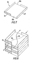
- an alternative embodiment of a heat exchanger assembly comprises a number of stacked trays 35 each having end and side walls 36, 37 respectively. Diagonally opposed portions 36a, 36b of the end walls 36 are cut out to define an air flow path. A number of these trays 35 are stacked together as shown in Figure 8 to define two opposing air flow paths 38, 39 which cross over within the length of the assembly.
- electrostatic dust collector shown in Figure 6b may be applied to any type of heat exchanger assembly such as those described herein, provided that the heat exchanger plates are electrically conducting. If plastic is used for the components of the heat exchanger, these may be made electrically conducting by coating the plastic with a thin layer of metal, this being known as metallised plastic.
Landscapes
- Engineering & Computer Science (AREA)
- Mechanical Engineering (AREA)
- General Engineering & Computer Science (AREA)
- Physics & Mathematics (AREA)
- Thermal Sciences (AREA)
- Chemical & Material Sciences (AREA)
- Combustion & Propulsion (AREA)
- Heat-Exchange Devices With Radiators And Conduit Assemblies (AREA)
- Air-Conditioning Room Units, And Self-Contained Units In General (AREA)
Applications Claiming Priority (2)
| Application Number | Priority Date | Filing Date | Title |
|---|---|---|---|
| GB858506415A GB8506415D0 (en) | 1985-03-12 | 1985-03-12 | Room ventilator |
| GB8506415 | 1985-03-12 |
Publications (2)
| Publication Number | Publication Date |
|---|---|
| EP0196175A2 true EP0196175A2 (fr) | 1986-10-01 |
| EP0196175A3 EP0196175A3 (fr) | 1988-05-11 |
Family
ID=10575888
Family Applications (1)
| Application Number | Title | Priority Date | Filing Date |
|---|---|---|---|
| EP86301591A Withdrawn EP0196175A3 (fr) | 1985-03-12 | 1986-03-06 | Ventilateur pour enceinte avec un bon rendement thermique |
Country Status (3)
| Country | Link |
|---|---|
| US (1) | US4799539A (fr) |
| EP (1) | EP0196175A3 (fr) |
| GB (1) | GB8506415D0 (fr) |
Cited By (6)
| Publication number | Priority date | Publication date | Assignee | Title |
|---|---|---|---|---|
| WO1994015162A1 (fr) * | 1992-12-24 | 1994-07-07 | Michael David Rose | Ameliorations relatives a des echangeurs de chaleur du type a plaques |
| FR2727505A1 (fr) * | 1994-11-28 | 1996-05-31 | Packinox Sa | Faisceau de plaques pour un echangeur thermique |
| EP0787953A3 (fr) * | 1996-02-02 | 1998-08-05 | Schako Metallwarenfabrik Ferdinand Schad Kg | Dispositif de conditionnement d'air avec récupération d'énergie |
| EP0803694A3 (fr) * | 1996-04-26 | 1999-03-03 | SKS Stakusit Bautechnik GmbH | Echangeur de chaleur à plaques |
| EP2894412A1 (fr) * | 2014-01-14 | 2015-07-15 | LUNOS Lüftungstechnik GmbH für Raumluftsysteme | Appareil d'aération destiné à l'aération intérieure de bâtiments |
| FR3071595A1 (fr) * | 2017-09-28 | 2019-03-29 | Elyt 3 | Echangeur air/air a double flux a contre-courant |
Families Citing this family (14)
| Publication number | Priority date | Publication date | Assignee | Title |
|---|---|---|---|---|
| DE4142177C2 (de) * | 1991-12-20 | 1994-04-28 | Balcke Duerr Ag | Plattenwärmetauscher |
| GB0006179D0 (en) * | 2000-03-16 | 2000-05-03 | Smiths Industries Plc | Units |
| FI114942B (fi) * | 2000-04-19 | 2005-01-31 | Mg Innovations Corp | Ilmastointilaite |
| EP1347260B1 (fr) * | 2000-12-25 | 2009-06-10 | Honda Giken Kogyo Kabushiki Kaisha | Echangeur thermique |
| JP4463437B2 (ja) * | 2001-01-31 | 2010-05-19 | 本田技研工業株式会社 | 一酸化炭素選択酸化除去装置および一酸化炭素選択酸化除去方法 |
| AU2003900835A0 (en) * | 2003-02-25 | 2003-03-13 | Air-Change Pty Limited | An air conditioning apparatus |
| KR100651879B1 (ko) * | 2005-08-16 | 2006-12-01 | 엘지전자 주식회사 | 환기시스템 |
| US10041743B2 (en) * | 2013-01-07 | 2018-08-07 | Carrier Corporation | Energy recovery ventilator |
| HRP20201062T1 (hr) * | 2014-12-18 | 2020-10-30 | Zehnder Group International Ag | Izmjenjivač topline i uređaj za ventilaciju s njime |
| AU2016246108B2 (en) * | 2015-01-26 | 2020-12-24 | Zehnder Group International Ag | Heat exchanger block and heat recovery ventilation unit comprising it |
| IL255877B (en) * | 2017-11-23 | 2019-12-31 | Dulberg Sharon | A device for extracting water from the air, and for drying the air using high energy and methods for its production |
| EP4664024A4 (fr) * | 2023-02-08 | 2026-04-29 | Sharp Kk | Échangeur de chaleur et système de ventilation à échange de chaleur total |
| WO2025141820A1 (fr) * | 2023-12-27 | 2025-07-03 | 三菱電機株式会社 | Élément d'échange de chaleur |
| WO2025164074A1 (fr) * | 2024-01-31 | 2025-08-07 | シャープ株式会社 | Dispositif de ventilation à échange de chaleur total et système de ventilation à échange de chaleur total |
Family Cites Families (13)
| Publication number | Priority date | Publication date | Assignee | Title |
|---|---|---|---|---|
| US1529711A (en) * | 1922-04-10 | 1925-03-17 | Walter C Parrott | Ventilating device |
| US1825498A (en) * | 1929-04-22 | 1931-09-29 | Selmer F Wogan | Unit for heating, cooling, and ventilating system |
| US1954456A (en) * | 1932-04-01 | 1934-04-10 | American Blower Corp | Air conditioning apparatus |
| US2074622A (en) * | 1933-06-03 | 1937-03-23 | Campbell Metal Window Corp | Ventilating and air treating provision |
| US3666007A (en) * | 1970-03-17 | 1972-05-30 | Mitsubishi Electric Corp | Apparatus for effecting continuous and simultaneous transfer of heat and moisture between two air streams |
| FR2039728A5 (fr) * | 1970-03-19 | 1971-01-15 | Mitsubishi Electric Corp | |
| DE2601016C2 (de) * | 1976-01-13 | 1984-08-23 | Ltg Lufttechnische Gmbh, 7000 Stuttgart | Verfahren und Einrichtung zum Reinigen von Filterkästen |
| DE2630667C3 (de) * | 1976-07-08 | 1982-01-07 | Interliz Anstalt, Vaduz | Lüftungsgerät |
| DE2713424C2 (de) * | 1977-03-26 | 1986-02-20 | Babcock-BSH AG vormals Büttner-Schilde-Haas AG, 4150 Krefeld | Einrichtung zur Beheizung und Belüftung von Räumen |
| US4384611A (en) * | 1978-05-15 | 1983-05-24 | Hxk Inc. | Heat exchanger |
| JPS5831239A (ja) * | 1981-08-18 | 1983-02-23 | Matsushita Electric Ind Co Ltd | 全熱交換空調装置 |
| US4512392A (en) * | 1983-01-18 | 1985-04-23 | Ee Dirk Van | Heat exchange apparatus |
| DE8301708U1 (de) * | 1983-01-22 | 1983-06-09 | Gretsch-Unitas Gmbh Baubeschlaege, 7257 Ditzingen, De | Lueftungsvorrichtung |
-
1985
- 1985-03-12 GB GB858506415A patent/GB8506415D0/en active Pending
-
1986
- 1986-03-06 EP EP86301591A patent/EP0196175A3/fr not_active Withdrawn
-
1987
- 1987-06-01 US US07/056,607 patent/US4799539A/en not_active Expired - Fee Related
Cited By (8)
| Publication number | Priority date | Publication date | Assignee | Title |
|---|---|---|---|---|
| WO1994015162A1 (fr) * | 1992-12-24 | 1994-07-07 | Michael David Rose | Ameliorations relatives a des echangeurs de chaleur du type a plaques |
| FR2727505A1 (fr) * | 1994-11-28 | 1996-05-31 | Packinox Sa | Faisceau de plaques pour un echangeur thermique |
| EP0715144A1 (fr) * | 1994-11-28 | 1996-06-05 | Packinox | Faisceau de plaques pour un échangeur thermique |
| EP0787953A3 (fr) * | 1996-02-02 | 1998-08-05 | Schako Metallwarenfabrik Ferdinand Schad Kg | Dispositif de conditionnement d'air avec récupération d'énergie |
| EP0803694A3 (fr) * | 1996-04-26 | 1999-03-03 | SKS Stakusit Bautechnik GmbH | Echangeur de chaleur à plaques |
| EP2894412A1 (fr) * | 2014-01-14 | 2015-07-15 | LUNOS Lüftungstechnik GmbH für Raumluftsysteme | Appareil d'aération destiné à l'aération intérieure de bâtiments |
| US9845959B2 (en) | 2014-01-14 | 2017-12-19 | Lunos Luftungstechnik Gmbh Fur Raumluftsysteme | Ventilation device for ventilation of rooms in buildings |
| FR3071595A1 (fr) * | 2017-09-28 | 2019-03-29 | Elyt 3 | Echangeur air/air a double flux a contre-courant |
Also Published As
| Publication number | Publication date |
|---|---|
| GB8506415D0 (en) | 1985-04-11 |
| US4799539A (en) | 1989-01-24 |
| EP0196175A3 (fr) | 1988-05-11 |
Similar Documents
| Publication | Publication Date | Title |
|---|---|---|
| EP0196175A2 (fr) | Ventilateur pour enceinte avec un bon rendement thermique | |
| JP3504277B2 (ja) | スイッチキャビネットの背壁、側壁またはドアとして組み付けるための冷却装置 | |
| CA1247450A (fr) | Appareil de ventilation | |
| KR860003477A (ko) | 클리인 루움(clean room) | |
| US4550773A (en) | Heat exchanger | |
| JP2667891B2 (ja) | とくに部屋の換気および空調用空気の一次側流体と二次側流体との間の独立形熱交換装置 | |
| KR20050122522A (ko) | 공기청정 겸용 환기시스템 | |
| EP2342504A1 (fr) | Système de ventilation et de climatisation modulaire intégré dans la façade | |
| KR101144591B1 (ko) | 창틀형 수직 전열교환 환기장치 | |
| KR102033420B1 (ko) | 환기구 장치 | |
| JPH10288357A (ja) | 熱交換換気装置 | |
| EP1837610A2 (fr) | Dispositif d'aération de pièce avec récupération de chaleur | |
| RU2232947C2 (ru) | Устройство подачи воздуха с радиатором | |
| KR20200041496A (ko) | 환기용 열교환장치 | |
| KR101932516B1 (ko) | 창호용 열교환 환기모듈 및 이를 구비한 환기 어셈블리 장치 | |
| CN110274316A (zh) | 一种带净化装置的窗 | |
| DE102006001724A1 (de) | Paket-Wandluftwärmetauscher mit Zu- und Abluftventilator | |
| KR101127006B1 (ko) | 스탠드형 전열교환 환기장치 | |
| JP3075017B2 (ja) | 天井埋込型空気調和機 | |
| JPH05133554A (ja) | 空気調和機 | |
| JP2597853B2 (ja) | クリーンルーム | |
| EP4343222B1 (fr) | Unité de ventilation à double flux avec de multiples orientations de fonctionnement | |
| KR20200001320A (ko) | 환기용 열교환장치 | |
| DE1922406A1 (de) | Waermetauscher fuer gasfoermige Medien | |
| JPH08178364A (ja) | 空気調和機の室外機 |
Legal Events
| Date | Code | Title | Description |
|---|---|---|---|
| PUAI | Public reference made under article 153(3) epc to a published international application that has entered the european phase |
Free format text: ORIGINAL CODE: 0009012 |
|
| AK | Designated contracting states |
Kind code of ref document: A2 Designated state(s): DE FR GB IT NL |
|
| PUAL | Search report despatched |
Free format text: ORIGINAL CODE: 0009013 |
|
| AK | Designated contracting states |
Kind code of ref document: A3 Designated state(s): DE FR GB IT NL |
|
| RAP1 | Party data changed (applicant data changed or rights of an application transferred) |
Owner name: PALMER, CHRISTOPHER JOHN Owner name: ADVANCE DESIGN & MANUFACTURE LIMITED |
|
| 17P | Request for examination filed |
Effective date: 19881111 |
|
| 17Q | First examination report despatched |
Effective date: 19890823 |
|
| STAA | Information on the status of an ep patent application or granted ep patent |
Free format text: STATUS: THE APPLICATION IS DEEMED TO BE WITHDRAWN |
|
| 18D | Application deemed to be withdrawn |
Effective date: 19900305 |