EP0196218A2 - Laser-Vorrichtung und Verfahren - Google Patents
Laser-Vorrichtung und Verfahren Download PDFInfo
- Publication number
- EP0196218A2 EP0196218A2 EP86302206A EP86302206A EP0196218A2 EP 0196218 A2 EP0196218 A2 EP 0196218A2 EP 86302206 A EP86302206 A EP 86302206A EP 86302206 A EP86302206 A EP 86302206A EP 0196218 A2 EP0196218 A2 EP 0196218A2
- Authority
- EP
- European Patent Office
- Prior art keywords
- discharge
- magnetic field
- cavity
- electrodes
- providing
- Prior art date
- Legal status (The legal status is an assumption and is not a legal conclusion. Google has not performed a legal analysis and makes no representation as to the accuracy of the status listed.)
- Granted
Links
Images


Classifications
-
- H—ELECTRICITY
- H01—ELECTRIC ELEMENTS
- H01S—DEVICES USING THE PROCESS OF LIGHT AMPLIFICATION BY STIMULATED EMISSION OF RADIATION [LASER] TO AMPLIFY OR GENERATE LIGHT; DEVICES USING STIMULATED EMISSION OF ELECTROMAGNETIC RADIATION IN WAVE RANGES OTHER THAN OPTICAL
- H01S3/00—Lasers, i.e. devices using stimulated emission of electromagnetic radiation in the infrared, visible or ultraviolet wave range
- H01S3/02—Constructional details
- H01S3/03—Constructional details of gas laser discharge tubes
-
- H—ELECTRICITY
- H01—ELECTRIC ELEMENTS
- H01S—DEVICES USING THE PROCESS OF LIGHT AMPLIFICATION BY STIMULATED EMISSION OF RADIATION [LASER] TO AMPLIFY OR GENERATE LIGHT; DEVICES USING STIMULATED EMISSION OF ELECTROMAGNETIC RADIATION IN WAVE RANGES OTHER THAN OPTICAL
- H01S3/00—Lasers, i.e. devices using stimulated emission of electromagnetic radiation in the infrared, visible or ultraviolet wave range
- H01S3/02—Constructional details
- H01S3/04—Arrangements for thermal management
- H01S3/041—Arrangements for thermal management for gas lasers
-
- H—ELECTRICITY
- H01—ELECTRIC ELEMENTS
- H01S—DEVICES USING THE PROCESS OF LIGHT AMPLIFICATION BY STIMULATED EMISSION OF RADIATION [LASER] TO AMPLIFY OR GENERATE LIGHT; DEVICES USING STIMULATED EMISSION OF ELECTROMAGNETIC RADIATION IN WAVE RANGES OTHER THAN OPTICAL
- H01S3/00—Lasers, i.e. devices using stimulated emission of electromagnetic radiation in the infrared, visible or ultraviolet wave range
- H01S3/09—Processes or apparatus for excitation, e.g. pumping
- H01S3/097—Processes or apparatus for excitation, e.g. pumping by gas discharge of a gas laser
- H01S3/0971—Processes or apparatus for excitation, e.g. pumping by gas discharge of a gas laser transversely excited
- H01S3/09713—Processes or apparatus for excitation, e.g. pumping by gas discharge of a gas laser transversely excited with auxiliary ionisation, e.g. double discharge excitation
- H01S3/09716—Processes or apparatus for excitation, e.g. pumping by gas discharge of a gas laser transversely excited with auxiliary ionisation, e.g. double discharge excitation by ionising radiation
Definitions
- This invention relates to an apparatus for creating a gaseous discharge with a particular application to a new type of gaseous discharge structure for use as a laser amplifier section.
- carbon dioxide lasers have fallen into five different categories.
- the most common construction is generally known as the “slow flow discharge tube”. This approach is limited to a maximum power output of about 75 watts per meter.
- the second category of carbon dioxide laser apparatus is the “convective flow” laser which achieves an increased power output at the expense of increased complexity.
- the third category is the "gas dynamic" laser which involves the use of rocket engine technology and, generally, is not suitable for commercial applications.
- the fourth category known as the "TEA” laser, is suitable for pulsed laser applications only.
- the fifth category is the "wave guide” laser which, at this time, appears to be best suited to applications of less than 100 watts.
- the primary difference between categories pertains to the construction method used for the laser amplification section.
- all common lasers contain various functional component parts, such as the optical systems, the electrical power supply, the laser amplification section, etc.
- the various categories of lasers are defined by the design approach used in the laser amplification section.
- the amplification section can be used as a component of both a laser oscillator and a laser amplifier.
- the key component in the laser amplification section is the electrical discharge apparatus.
- electrical discharges are key components in other fields.
- a new electrical discharge apparatus which makes possible a new laser amplification section design.
- Prior art 1 and 2 show a magnetic field to stabilize an electrical discharge in a cylindrical volume in a transverse flowing gas stream.
- Prior art 8 deals with a "Transverse Zeeman Laser.”
- This class of laser differs from the present invention since it has a different cavity shape, objective, electric field configuration and magnetic field configuration.
- the electrical discharge is pressed against the wall of the discharge tube, thereby reducing the volume of the discharge.
- Prior art 9 describes a small electro-magnetic pump in the side arm of the CO 2 laser for circulating gas.
- this invention teaches a new method and apparatus for achieving a uniform electical discharge under conditions which would not normally be electrically stable or under conditions where the electrical discharge would not evenly fill a desired volume. Further teachings of this invention deal with applying this new type of electrical discharge to the construction of molecular lasers, such as C0 2 lasers. When applied to C0 2 lasers, the resultant laser represents a new category of C0 2 laser, which may be termed a "Macken Discharge Laser.”
- the features include a laser apparatus which exhibits increased power output per unit length compared to the slow flow discharge tube laser, but without the necessity of the rapidly flowing gas of convective flow lasers.
- the present invention provides laser apparatus having a cavity which is at least partially bounded by two facing surfaces which are closely spaced and characterised by electrode means for establishing an electric field and an electric discharge within the cavity the orientation of the electric field being substantially parallel to the facing surfaces and means for establishing a magnetic field within the cavity with at least a major vector component substantially perpendicular to the facing surfaces, the arrangement being such that in operation the electric discharge extends between the said surfaces for a distance substantially greater than the separation of the said surfaces.
- the invention provides a method of producing a substantially uniform broad area electric discharge including: providing a gas filled cavity between two relatively closely spaced surfaces and characterised by; providing a magnetic field in a direction substantially orthogonal to said surfaces; and providing at least one electrical discharge within said gas filled cavity oriented with the electric field gradient thereof substantially parallel to said surfaces for enabling the action of said magnetic field to spread said discharge substantially uniformly over a distance substantial greater than the separation of the said surfaces.
- the present invention provides a new type of structure for the amplification section of a laser apparatus.
- This structure includes a cavity which generally is bounded by two facing surfaces, closely spaced relative to the dimensions of the surfaces.
- a magnetic field is established in a direction perpendicular to the surfaces.
- the electrode design and cavity configuration shape the electric field so that the electric field is relatively narrow in the dimension parallel to the magnetic field compared to the dimension perpendicular to both the magnetic field vector and the electric field vector.
- the electrodes usually form two elongated electrode regions which extend over a distance considerably longer than the distance separating these two oppositely charged series of electrodes.
- the magnetic field exerts a force on the charged particles in the discharge which tends to move the discharge down the length of the electrode regions. Below a certain level of magnetic field strength this effect exhibits itself as a series of discharges moving down the two elongated electrodes. Above a certain magnetic field strength, the discharge becomes uniform and very stable.
- the rate of heat removal from the gas can be greatly increased and it is possible to obtain substantially higher powers per unit length when dealing with thermally limited lasers, such as C0 2 lasers.
- two generally planar surfaces are used to form the cavity, while another embodiment utilizes two concentric cylinders to form the cavity.
- Prior art glow electrical discharges tend to become unstable under many conditions which would otherwise be desirable for the construction of laser amplification sections. With such discharges, at high gaseous pressures or high currents, the discharges tend to form streamers or arcs which are not suitable for proper excitation of the gaseous medium. Therefore, pulsed gas lasers can benefit from this invention.
- the new type of discharge described herein uniformly fills the volume between two closely spaced plates, such as rectangular surfaces. With cooling of the plates, the heat removal rate from the gas between these plates is increased generally proportionally to the aspect ratio (width of cavity divided by plate separation) compared to an equal length gaseous discharge tube.
- the laser output power would actually be less per meter of length than is achieved by a discharge in a cooled cylindrical tube.
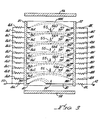
- a discharge amplification section generally designated 10, of a laser apparatus.
- the section 10 is formed as an envelope, in the form of a generally box-like rectangular sandwich configuration including two facing surfaces 16 and 18 which are closely spaced relative to their width and length surface dimensions. The surfaces are sufficiently electrically insulating to perform the functions which will be discussed later.
- Preferred materials for surface 16 and 18 are porcelain, ceramic or glass.
- Surfaces 16 and 18 are backed by plates 12 and 14 respectively. These plates provide structural support for surfaces 16 and 18 and therefore could be made of any suitable structural material, including possibly the same material as surface 16 and 18 (such as glass). However, since it is desirable for plates 12 and 14 to also thermally conduct heat, it is desirable for these plates to be of metal. In the preferred embodiment, plates 12 and 14 are made of a ferromagnetic material such as steel, for reasons to be explained later.
- the plate-like members 12 and 14 are illustrated as being formed of a material which has an adequately high thermal conductivity and which is sufficiently thick for the formation therein of thermal cooling channels.
- Thermal cooling channels 34A and 34B are formed in plate 12, and channels 37A and 37B are formed in plate 14. Tubes, not shown, are connected to these cooling channels and a cooling liquid is circulated through these openings so as to cool plates 12 and 14. In this manner, through thermal conduction, surfaces 16 and 18, which form a major portion of the walls of the cavity 24, are cooled.
- the volume of cavity 24 is filled with a gas, which in this example is a carbon dioxide, nitrogen and helium mixture.
- Suitable magnetic field producing means are provided by permanent magnets 26-and 28.
- the magnets 26 and 28 are arranged and positioned with the polarity aligned in a direction generally perpendicular to the plane of the plates 12 and 14. That is, as shown in Figures 1 and 2, the north pole of the lower magnet 28 abuts the plate 14, while the south pole of the upper magnet 26 abuts the surface of plate 12. These polarities are shown by conventional designations "N" and "S” marked on the magnets 26 and 28 in the drawings.
- the arrow #42 in Figure 2 indicates the magnetic field direction.
- the magnets 26 and 28 preferably have a size or dimension approximating the size or dimension of the plate-like members 12 and 14 for the sake of easiest magnetic field generation.
- the magnets 26 and 28 are permanent magnets which may be formed of relatively inexpensive barium iron oxide ceramic materials, or the like. It is to be understood that other devices may be used for generating the required magnetic field such as other permanent magnets, DC electromagnets or AC electromagnets.
- the objective is to generate a field within cavity 24 with at least a major vector component perpendicular to the surfaces 16 and 18. If the magnetic field produced by the magnets 26 and 28 needs to be made more uniform, it has been found that making plates 12 and 14 from steel helps to make the magnetic field very uniform.
- steel plates 30, 31, 32, 33 ( Figure 2) form a generally rectangular tube and surround the magnets and other parts of the struture. Plates 31 and 33 are not shown in Figures 1, 3 and 4, (to better illustrate the other components) but plates 31 and 33 are generally the same length as 30.
- This ferromagnetic tubular structure (shown rectangular, but other shapes can be used) forms a magnetic circuit giving a low magnetic reluctance path for the magnetic lines which emanate from the north pole of 26 and enter the south pole of 28.
- This magnetic circuit is part of a preferred embodiment, but not absolutely necessary to the function of the invention because the function of the magnetic circuit is to minimize the size and expense of the magnets 26 and 28, as well as confine the magnetic field to structure 10. Eliminating plates 30, 31, 32, and 33 would require magnets 26 and 28 to be much stronger.
- the side wall members 20 and 22 are preferably formed of a suitable non-magnetic material. Wall members 20 and 22 should also be electrically insulated from each other. These side wall members maintain the spacing between surfaces 16 and 18, and support the electrode structure, which includes first and second sets of electrodes. These sets of electrodes are generally designated 36 and 38, with electrodes of each set bearing supplementary letter suffix designations, i.e., 36A, 36B, etc.
- the set 36 of electrodes are depicted as being generally parallel, equally spaced rod-type electrodes, arranged in parallel with one another, and extending through and supported by, side wall member 20.
- electrode set 38 includes electrodes which are generally parallel to one another and in axial alignment with the corresponding electrode of set 36.
- the electrode set 38 extends through and is supported by side wall member 22. However, the electrodes do not make electrical contact with side wall members 20 and 22. It is to be understood that the electrodes depicted here are examples only. Within the general objective of forming two elongate electrode regions, there is great flexibility as to the electrode design. In particular, if the set 36 of electrodes are negatively charged cathodes operating at certain gas pressures, then larger surface area electrodes may be preferable, but not necessary.
- each set 36 and 38 extend into the cavity 24 for the same distance and that they are used to form an electric field designated 39.
- the electrode 40 is representative of single or multiple electrodes used to initiate the electrical discharge. This function will be discussed later.
- the electrodes are provided with suitable ballast devices such as resistors.
- Resistors 46A-46L are coupled in series with electrodes 36A-36K respectively, while resistors 48A-48L are coupled in series with electrodes 38A-38K and 40 respectively.
- the resistors designated 46 have the other ends thereof coupled together for electrical connection to a terminal 50 of a suitable power source.
- Resistors designated 48 likewise have the other ends thereof coupled together for electrical connection to the other terminal 52 of the power source. In this illustration, terminal 50 is negatively charged and terminal 52 is positively charged.
- the electrical and magnetic polarities used are examples only.
- resistors 46A-46L and 48A-48L define elongated electrode regions. It may also be possible to replace the multiple linear array of electrodes 36A-36K or 38A-38F with a single electrode, such as a rod made of a suitable electrical conductor. For optimum performance, the rod electrode should be placed so that it approximately passes through the points in space defined by the tips of electrodes 36A-36K, thereby extending over the same elongated electrode region. Similarly, another rod may be used to replace multiple electrodes 38A-38K. These rod electrodes should be connected to the positive and negative terminals of the power source respectively. It is to be understood that the optimum electrode configuration can be determined experimentally by those skilled in the art.
- the laser mirrors 54 and 56 are shown adjacent to opposite ends of the cavity 24. These mirrors are shown as a point of reference only. The preparation of mirrors optimized for this rectangular geometry is within the capabilities of persons skilled in the art. Alternatively, the ends of the cavity 24 could be closed with totally transparent windows positioned at the locations of mirrors 54 and 56. An externally generated laser beam may be passed through the windows so as to be amplified by the amplifier section 10. In any event, it is to be understood that the cavity 24 is suitably sealed to act as an envelope containing the gas mixture therein.
- a direct current power source is connected to terminals 50 and 52, with terminal 52 being positive.
- the direction of the magnetic field generated by magnets 26 and 28 is as indicated by the pole designations shown in Figures 1 and 2.
- the close proximity of electrode 40 to electrode 36A rapidly initiates an electrical discharge at the end of the cavity 24 and the action of the magnetic field results in the continuous generation of new discharges.
- the action of the magnetic field is such as to exert a force on the discharge.
- the action of the magnetic field is to cause these discrete discharges to sweep in the direction indicated by the arrows shown in Figure 3. This condition can be termed "discrete moving discharges".
- P is the total gas pressure in torr.
- the speed of transverse motion of the electrical discharges would be 26 meters per second.
- the above formula is based on measurements where a single discharge moves up stream against a flowing gas. At magnetic field strengths which establish a Macken discharge, experiments have shown that the above formula no longer applies because the leading edge of a discrete discharge moves at a faster rate than the trailing edge. This means that the discharge spreads in width as it travels down the cavity. This appears to provide the mechanism for discrete discharges to merge into one homogeneous discharge.
- the magnetic force acts primarily on the electrons in the electrical discharge. This is because the electrons are moving many times faster than the much heavier ionized atoms and molecules.
- the formula for the force (F ) exerted by a magnetic field of strength B of a particle of charge Q travelling with a velocity V is given by the formula: Where x is the mathematical notion referred to as 'cross'.
- Equation 1 gives a general formula for the velocity of moving discharges in a CO 2 laser gas.
- Equation 4 If “t”, in Equation 4, is set equal to the thermal time constant "T” from equation 3 and if “d” is set to equal the cavity separation dimension L from equation 3, then substituting equation 1 for velocity "v” in equation 4, the solution to this equation shows that 80 gauss is needed to cause the discharge to sweep a distance equal to the cavity separation distance in one thermal time constant for a 1 cm wide cavity. This value is independent of pressure.
- 80 gauss a reasonable condition for defining the minimum magnetic field for the claimed effect is 80 gauss. While 80 gauss will not necessarily produce a uniform thermal heating of the gas, 80 gauss does produce a distinct thermal wake left behind moving discharges for a CO 2 , N 2 , He gas mixture. In other, yet untested, gases the constants will differ, but also from experiments, 80 gauss is considered to be a good standard for the initiation of the effect.
- the Macken discharge condition starts at a higher magnetic field which depends on many factors. These factors include: gas pressure, current density, cavity configuration and electrode configuration. The required threshold magnetic field needs to be determined experimentally.
- the maximum suitable magnetic field strength can reasonably be set at the saturation flux density of iron which is about 22,000 gauss.
- the gas pressure was initially about 18 torr for a standard laser mix of carbon dioxide, nitrogen and helium.
- the discharge voltage was 1,800 volts at a current of about 1 amp.
- the resistors 46 were 20,000 ohms each and resistors 48 were 10,000 ohms each.
- the discharges were found to have completely merged as indicated by monitoring the current across an individual resistor, such as resistor 48E. Also, visual inspection revealed good uniformity.
- the magnetic field strength was reduced to 750 gauss by removing a magnet layer corresponding to magnet 26 in Figure 1 (forming a structure analagous to Figure 8), the discharge was found to still be completely uniform.
- the electrode 40 is closer spaced to the oppositely charged electrodes rather than the other electrodes in group 38. Ths electrode 40 is representative of launcher electrodes. Optional ballast resistor 48L is provided in this electrode. It is also possible to eliminate electrode 40 and to generate the necessary electric field strength to initiate new discharge between electrodes 38A and 36A. To do this, the power supply voltage and the ballast resistor size must be sufficient to initiate a discharge when current stops flowing to anode 38A.
- alternating current power may be applied at terminals 50 and 52, in which event it may be necessry to have launcher electrodes similar to electrode 40 at each end of the structure.
- the electrodes may also be positionsed at opposite ends in non-interference with the optics. In this case, the direction of electrical discharges would change by 9 0 degrees, but electrical discharges would still flow in a direction perpendicular to the applied magnetic field.
- electromagnets may replace the permanent magnets, with multi-phase AC power applied thereto to generate moving magnetic fields.
- Open loop discharges generally have electric field equipotential lines that leave the cavity without closing on themselves.
- the electric field arrows 39 are the electric field gradient, also known as the electric field vector.
- the equipotential lines are perpendicular to the electic field vector.
- closed loop discharges There is another group of sweeping discharges known as " closed loop discharges". These are depicted in Figures 5 and 6.
- the closed loop discharges do not need continuous initiation of new discharges.
- the discharges sweep around a closed loop forming the equivalent of an infinitely long open loop system.
- the electric field equipotential lines also form closed loops inside the cavity in this type of structure.
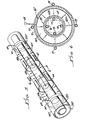
- FIG. 5 and 6 taken together, there is shown an alternate embodiment in which coaxial, cylindrical geometry is used rather than the planar parallel geometry of Figures 1 through 4.
- the cylindrical cavity 59 is bounded by two coaxial surfaces 16T and 18T corresponding to surface 16 and 18 in Figures 1-4.
- Surfaces 16T and 18T are sufficiently electrically insulating so that an electrical discharge would tend to pass through the gas contained in cavity 24T.
- Inside surface 18T there are axially aligned and spaced ferro-magnetic cylinders 62A, B, C, as shown in Figure 5.
- These ferro-magnetic cylinders are magnetized by permanent magnets 63A and 63B in axial alignment therewith in the spaces there between.
- the magnets 63A and 63B are positioned with repelling polar orientation, as shown at either end of 62B.
- the magnetic field for these magnets is shown in Figure 5.
- magnetic cylinder 62B serves as the south pole of the magnet over its length
- cylinders 62A and 62C serve as the north pole of the magnet over their entire length.
- cylinder 70 is a ferro-magnetic cylinder which runs the length of cylinder 16T except for appropriate openings to allow for terminals 68 and 69 which are connected to electrodes 64 and 65.
- Cylinder 70 serves a dual purpose since it forms a part of the magnetic circuit which connects the south pole of the cylinder 62B to the north pole of cylinders 62A and 62C.
- the radially extending arrows 42T in Figure 5 and other unmarked arrows inside the cavity 24T in both Figures 5 and 6 indicate the local direction of the magnetic field extending between cylinders 62A, 62B, and 62C and the outside cylinder 70 shown in Figure 6.
- This magnetic field is analagous to magnetic field 42 in Figure 1 to 4 :
- arrows 39T show the broad area electric field analagous to 39 in Figures 2 to 4.
- cylinder 70 includes four water cooling tubes 71-74, inclusive, which make thermal contact with this metallic cylinder. These tubes are representative of a cooling method which may be employed for cooling surface 16T. In this case. there would be thermal conduction from the cooled tubes 71-74 through the cylinder 70 and, ultimately, to the surface 16T.
- the inside metallic cylinders 62A, 62B and 62C are cooled by tubes 75-78 shown in Figure 6.
- these inside cooling tubes are not shown in Figure 5.
- This cooling method is an example only. Many other cooling methods are possible. Also, in cases such as intermittant operation, no liquid cooling may be required.
- a voltage is applied to terminals 68 and 69, a broad area electric field 39T and an electrical discharge is established through the cavity 24T between electrodes 64 and 65.
- These electrodes are analogous to the 36 series and 38 series electrodes, therefore they can also be segmented and are considered elongated electrode regions.
- the radial magnetic fields cause the discharge to rapidly rotate. If the magnetic field is sufficiently strong, the discharge will form a circle when viewed from the angle shown in Figure 6.
- the discharge can become a Macken discharge similar to the process previously described for the parallel geometry described in conjunction with Figure 4.
- Reference texts 1 and 2 Of particular interest in reference texts 1 and 2 is the information dealing with the breakdown voltage gradient, the voltage-current curve, and the requirements for stabilizing a convention discharge. References 3 and 4 deal with general effects of a magnetic field on an electrical discharge.
- the co-operative feature of these four elements is especially important in achieving a Macken discharge. It is possible to adjust the parameters of some of the elements to compensate for less than ideal conditions on other elements.
- the cavity shape and the electrodes together control the electric field shape.
- the electric field shape must at least permit the formation of a broad area sweeping discharge, but ideally, through the use of multiple ballasted electrodes and careful shaping, the electric field should encourage the spreading of the electric discharge.
- inadequacies in this ideal can be offset by increasing the magnetic field strength or an adjustment in the gas composition or pressure.
- optional thin metallic cylindrical surfaces 66 and 67 are placed in contact with the inside of surface 16T at the positions adjacent to magnets 63A and 63B, respectively.
- These cylinders 66 and 67 serve as electrodes and provide one means for the rotating electric discharges to deal with the anomaly that occurs when the direction of the magnetic field is being reversed, for example, between cylinders 62C and 62B.
- this electrical discharge would terminate on the near surface of electrode 66.
- the discharge would then re-emerge on the other end of electrode 66 and be rotating counter clockwise as the discharge passed through the region near cylinder 62B.
- the discharge would then terminate on the near edge of electrode 67 and reappear on the far side of the electrode 67, once more rotating clockwise and terminating in electrode 65.
- Figures 1-6 show the major design philosophy, there are variations which are possible.
- Figures 7 and 8 show design variations to the magnetic circuit used in Figure 2 so as to supply a magnetic field to a generally rectangular cavity similar to that shown in Figures 1-4.
- Figure 7 shows only the parts which form the magnetic circuit components of the structure and a few other components needed for clarity. It does not show any of the electrodes, wires, cooling, discharge, etc., which do not form part of the magnetic circuit.
- the numbering corresponds to comparable components in Figures 1, 2 and 3 except that the letter "M" is added after the number. Therefore, the cavity 24M is formed between relatively closely spaced facing surfaces 16M and 18M.
- Support members 20M and 22M form walls of the cavity.
- Ferromagnetic (preferably steel) plate 30M performs the function of both plates 30 and 12 in Figure 2.
- plate 32M performs the function of plates 32 and 14 in Figure 2.
- Magnets 28M and 26M are placed between ferromagnetic plates 30M and 32M.
- the ferromagnetic plates transfer the magnetic field generated by said magnets and distributes relatively evenly the magnetic field in cavity 24M, with the magnetic field vector shown by 42M. Note that this structure does reverse the direction of the magnetic field vector inside the cavity compared to Figure 2, even though both figures are depicted with the north pole of the magnet up.
- the cavity dimension in the direction of the magnetic field vector is shown as being generally the same as the magnet dimension in the magnetized direction. If it is desired to make the magnet thicker or thinner than the cavity, it is possible to either machine plates 30M and 32M to accommodate the height difference. Alternatively, the magnets may be placed alongside of plates 30M and 32M with the use of steel plates as magnetic coupling elements to transfer the magnetic field into plates 30M and 32M.
- Figure 8 also shows only the elements of the structure related to the magnetic circuit.
- Figure 8 is very similar to Figure 2.
- the numbering of comparable parts is the same except for the use of the letter "P".
- the major exceptions are that magnet 26 and plate 12 have been elimated.
- the dielectric surface 16 has been placed directly on plate 30P.
- plate 14P could be made of any structurally suitable material.
- steel is the preferred material since steel also has the property of making the magnetic field in cavity 24P very uniform. Note that if steel is used for 14P, there should be a suitable gap between 14P and 33P or 31P to prevent a magnetic "short circuit".
- the magnetic circuits described in Figures 1 to 8 have the same basic elements and purpose.
- the fundamental purpose is to: 1) establish a low reluctance (high permiability) path between the two poles of a magnet with (ideally) the only gap in the path being the cavity and the non magnetic materials associated with the cavity; 2) uniformly distribute the magnetic field in the cavity and orientate it generally perpendicular to the facing surfaces; 3) establish a sufficiently strong magnetic field in the cavity.
- all of the magnetic circuit designs include: 1) at least one magnet; 2) a cavity; 3) ferromagnetic pieces backing the relatively closely spaced facing surfaces of the cavity; 4) no major magnetic "short circuiting" connection to the ferromagnetic backing pieces which would substantially reduce the magnetic field in the cavity; 5) a magnetic circuit design which provides a ferromagnetic return path as needed to complete the magnetic circuit. From the teachings presented here, it is possible to make a variety of magnetic circuits including stacked, multi cavity laser structures.
- a cylindrical geometry could be made which would be analagous to wrapping the planar geometry cavity depicted in Figure 3 into a cylindrical geometry, with the cylindrical axis being parallel to the arrows shown on the discharges 58C and 58E.
- another configuration would comprise cylindrical geometry which eliminates magnets 63A and 63B in Figure 5. This could be achieved by replacing them with cylindrical magnets which would be placed in the space between cylinders #70 and #61T in Figure 6. These cylindrical magnets would be radially magnetized with periodically reversed polarity to produce the same type of magnetic field distribution in the cavity as is depicted in Figures 5 and 6.
- ferromagnetic cylinders 62A, 62B, and 62C with one continuous ferromagnetic cylinder.
- Figures 5 and 6 are representative of a class called “closed loop discharge apparatus.”
- Figures 1-4 are representative of a class called “open loop discharge apparatus.”
- closed loop discharge apparatus Several variations on the closed loop discharge exist. For example, it is possible to combine two structures similar to Figure 7 with one placed one on top of the other. They would be oriented with the same magnetic polarity on the middle plate between the two cavities and the middle plate would also have a complete dielectric coating. With an external envelope to maintain the partial vacuum, it would be possible for the discharge to form a continuous loop by first sweeping through the top cavity then flipping into the bottom cavity to complete the loop.
- the rectangular cavity has three dimensions which will be called: (e), parallel to the electric field; (b), parallel to the magnetic field; and (s), parallel to the sweeping direction.
- (b) is much smaller than (e)
- (e) is smaller than (s).
- the electric discharge has no problem being stabilized in the (e) direction, as long as some ballasting means are provided to limit the current within the gas.
- the electric discharge even moves around charged particles creating space charges and local voltage gradients as needed to form a stable condition in the (e) direction.
- the size of the cavity and the pressure of the gas have been chosen to stablize the discharge. This form of stabilizaion is commonly referred to as "wall stabilization.”
- the (s) dimension is chosen to be large.
- the electric field is usually a fairly uniform potential parallel to the (s) direction. Without any other means of dispersing the discharge in the (s) direction, the discharge will assume a width in the (s) direction roughly equal to the (b) dimension. This forms a fairly round discharge which will usually wander around in the (s) dimension.
- the restriction in the size of the discharge in the (s) dimension is believed to be because the heating of the gas lowers the discharge voltage gradient in a narrow channel. This is referred to as thermal confinement of the discharge.
- the objective is to introduce a new force in the (s) dimension to overcome this thermal confinement.
- a magnetic field is used to introduce this force on the discharge. For example, it has been calculated that at about 40 gauss, the force becomes sufficient to move the discharge through the gas at a rate where the discharge moves one wall separation distance (b) in a time equal to the thermal time constant of the gas. This condition still exhibits thermal confinement, but the effectss have been reduced.
- a pulsed ultra violet laser with a cylindrical tube which contains two parallel elongated electrode regions extending down the length of the cylinder and generally located near the cylinder walls being opposite each other across the axis of the cylinder. These two elongated electrode regions form a broad area electric field with the magnetic field extending perpendicular to the electric field vector and the length of the cylinder.
- the pulsed power supply energizing these electrodes could provide the needed electrical excitation.
- two facing surfaces does not necessarily mean that there has to be a physical brake between these surfaces. Also, it is to be understood that the addition of multiple layers or levels of cavities with “two facing surfaces” in each layer or level does not constitute a departure from the invention.
- the facing surfaces should be sufficiently electrically insulating that an applied voltage parallel to the surfaces produces an electric discharge through the gas.
- segmented electrically conductive pieces can be used for a discharge cavity if they are cut up in short enough lengths and electrically insulated from each other. These pieces are an example of being “effectively electrically insulating” because they are electrically insulating to the electrical discharge.
- the portion of the magnetic field vector component which is parallel to the median has an undesirable effect and is a waste of magnetic field strength, but it can be tolerated.
- the term "magnet” is use to denote any source of magnetic field including permanent magnets and electro magnets. The use of permanent magnets in the examples is only an illustration.
- the term “magnetic circuit” and “short circuit” are both making analogies with electrical circuits.
- the use of ballast resistors or "ballast” is to be understood as being representative of any current limiting means, such as ballast tubes, transistors or current limited power supplies. Even a cathode run at current densities called the "abnormal glow" exhibit a type of distributed ballasting. Even a single elongated electrode could conceivably have a resistive layer producing the equivalent effect of multiple ballasted electrodes.
Landscapes
- Physics & Mathematics (AREA)
- Electromagnetism (AREA)
- Engineering & Computer Science (AREA)
- Plasma & Fusion (AREA)
- Optics & Photonics (AREA)
- Health & Medical Sciences (AREA)
- Toxicology (AREA)
- Lasers (AREA)
Applications Claiming Priority (2)
| Application Number | Priority Date | Filing Date | Title |
|---|---|---|---|
| US71545885A | 1985-03-25 | 1985-03-25 | |
| US715458 | 1985-03-25 |
Publications (3)
| Publication Number | Publication Date |
|---|---|
| EP0196218A2 true EP0196218A2 (de) | 1986-10-01 |
| EP0196218A3 EP0196218A3 (en) | 1988-11-30 |
| EP0196218B1 EP0196218B1 (de) | 1993-10-27 |
Family
ID=24874134
Family Applications (1)
| Application Number | Title | Priority Date | Filing Date |
|---|---|---|---|
| EP19860302206 Expired - Lifetime EP0196218B1 (de) | 1985-03-25 | 1986-03-25 | Laser-Vorrichtung und Verfahren |
Country Status (3)
| Country | Link |
|---|---|
| EP (1) | EP0196218B1 (de) |
| CA (1) | CA1259396A (de) |
| DE (1) | DE3689201T2 (de) |
Cited By (2)
| Publication number | Priority date | Publication date | Assignee | Title |
|---|---|---|---|---|
| GB2205991A (en) * | 1987-05-15 | 1988-12-21 | Galram Technology Ind Ltd | Gas discharge laser |
| CN102118006B (zh) * | 2009-12-30 | 2012-06-27 | 杭州中科新松光电有限公司 | 一种大功率气体激光器光腔真空调试工艺 |
Family Cites Families (3)
| Publication number | Priority date | Publication date | Assignee | Title |
|---|---|---|---|---|
| US3413568A (en) * | 1965-06-22 | 1968-11-26 | Bell Telephone Labor Inc | Reversed axial magnetic fields in lasers |
| FR1557756A (de) * | 1967-12-01 | 1969-02-21 | ||
| US4035741A (en) * | 1975-02-14 | 1977-07-12 | Owens-Illinois, Inc. | Magnetic polarization of tubular laser |
-
1986
- 1986-03-24 CA CA000504850A patent/CA1259396A/en not_active Expired
- 1986-03-25 EP EP19860302206 patent/EP0196218B1/de not_active Expired - Lifetime
- 1986-03-25 DE DE19863689201 patent/DE3689201T2/de not_active Expired - Fee Related
Cited By (3)
| Publication number | Priority date | Publication date | Assignee | Title |
|---|---|---|---|---|
| GB2205991A (en) * | 1987-05-15 | 1988-12-21 | Galram Technology Ind Ltd | Gas discharge laser |
| GB2205991B (en) * | 1987-05-15 | 1991-12-11 | Galram Technology Ind Ltd | Gas discharge laser |
| CN102118006B (zh) * | 2009-12-30 | 2012-06-27 | 杭州中科新松光电有限公司 | 一种大功率气体激光器光腔真空调试工艺 |
Also Published As
| Publication number | Publication date |
|---|---|
| DE3689201T2 (de) | 1994-04-21 |
| EP0196218A3 (en) | 1988-11-30 |
| EP0196218B1 (de) | 1993-10-27 |
| DE3689201D1 (de) | 1993-12-02 |
| CA1259396A (en) | 1989-09-12 |
Similar Documents
| Publication | Publication Date | Title |
|---|---|---|
| US4755999A (en) | Laser apparatus utilizing a magnetically enhanced electrical discharge | |
| US4025818A (en) | Wire ion plasma electron gun | |
| US3886479A (en) | Electrode systems for gas discharge devices particularly gas lasers | |
| CA1147048A (en) | High power laser and cathode structure therefor | |
| US4601039A (en) | Inductively stabilized, long pulse duration transverse discharge apparatus | |
| US4677637A (en) | TE laser amplifier | |
| US3761836A (en) | Magnetically compensated cross field flowing gas laser | |
| EP0196218B1 (de) | Laser-Vorrichtung und Verfahren | |
| JPH04124892A (ja) | 自由電子レーザ | |
| Korzekwa et al. | The influence of magnetic fields on dielectric surface flashover | |
| Myshenkov et al. | Prospects for using high-frequency capacitative discharges in lasers | |
| Bykov et al. | Development of long-lifetime cold cathodes | |
| Targ et al. | High-repetition-rate xenon laser with transverse excitation | |
| JPH0671108B2 (ja) | 磁気的に高められた放電を利用するレ−ザ−装置 | |
| US3747015A (en) | Magnetic stabilized cross field flowing gas laser | |
| Shi et al. | Experimental investigation on the current carried by a cathode spot of vacuum arc in axial magnetic fields | |
| JPH0329196B2 (de) | ||
| Harry et al. | Multiple electrode system for high power CO2 laser excitation | |
| US4723255A (en) | Extended lifetime railgap switch | |
| GB2107512A (en) | Apparatus for producing a laser-active state in a fast subsonic flow | |
| US4574380A (en) | Self-optimizing electrode and pulse-stabilized super high power C.W. gas lasers | |
| JPH01138773A (ja) | レーザー | |
| US6050215A (en) | Plasma stream generator with a closed configuration arc | |
| Jennings et al. | Comparison of hollow cathode and conventional argon ion lasers | |
| US4596017A (en) | Electron beam method and apparatus for obtaining uniform discharges in electrically pumped gas lasers |
Legal Events
| Date | Code | Title | Description |
|---|---|---|---|
| PUAI | Public reference made under article 153(3) epc to a published international application that has entered the european phase |
Free format text: ORIGINAL CODE: 0009012 |
|
| AK | Designated contracting states |
Kind code of ref document: A2 Designated state(s): CH DE FR GB IT LI NL |
|
| PUAL | Search report despatched |
Free format text: ORIGINAL CODE: 0009013 |
|
| AK | Designated contracting states |
Kind code of ref document: A3 Designated state(s): CH DE FR GB IT LI NL |
|
| 17P | Request for examination filed |
Effective date: 19890530 |
|
| 17Q | First examination report despatched |
Effective date: 19910911 |
|
| GRAA | (expected) grant |
Free format text: ORIGINAL CODE: 0009210 |
|
| AK | Designated contracting states |
Kind code of ref document: B1 Designated state(s): CH DE FR GB IT LI NL |
|
| PG25 | Lapsed in a contracting state [announced via postgrant information from national office to epo] |
Ref country code: NL Effective date: 19931027 Ref country code: LI Effective date: 19931027 Ref country code: FR Effective date: 19931027 Ref country code: CH Effective date: 19931027 |
|
| ITF | It: translation for a ep patent filed | ||
| REF | Corresponds to: |
Ref document number: 3689201 Country of ref document: DE Date of ref document: 19931202 |
|
| REG | Reference to a national code |
Ref country code: CH Ref legal event code: PL |
|
| EN | Fr: translation not filed | ||
| NLV1 | Nl: lapsed or annulled due to failure to fulfill the requirements of art. 29p and 29m of the patents act | ||
| PLBE | No opposition filed within time limit |
Free format text: ORIGINAL CODE: 0009261 |
|
| STAA | Information on the status of an ep patent application or granted ep patent |
Free format text: STATUS: NO OPPOSITION FILED WITHIN TIME LIMIT |
|
| 26N | No opposition filed | ||
| PGFP | Annual fee paid to national office [announced via postgrant information from national office to epo] |
Ref country code: DE Payment date: 20010319 Year of fee payment: 16 |
|
| PGFP | Annual fee paid to national office [announced via postgrant information from national office to epo] |
Ref country code: GB Payment date: 20010321 Year of fee payment: 16 |
|
| REG | Reference to a national code |
Ref country code: GB Ref legal event code: IF02 |
|
| PG25 | Lapsed in a contracting state [announced via postgrant information from national office to epo] |
Ref country code: GB Free format text: LAPSE BECAUSE OF NON-PAYMENT OF DUE FEES Effective date: 20020325 |
|
| PG25 | Lapsed in a contracting state [announced via postgrant information from national office to epo] |
Ref country code: DE Free format text: LAPSE BECAUSE OF NON-PAYMENT OF DUE FEES Effective date: 20021001 |
|
| GBPC | Gb: european patent ceased through non-payment of renewal fee |
Effective date: 20020325 |
|
| PG25 | Lapsed in a contracting state [announced via postgrant information from national office to epo] |
Ref country code: IT Free format text: LAPSE BECAUSE OF NON-PAYMENT OF DUE FEES;WARNING: LAPSES OF ITALIAN PATENTS WITH EFFECTIVE DATE BEFORE 2007 MAY HAVE OCCURRED AT ANY TIME BEFORE 2007. THE CORRECT EFFECTIVE DATE MAY BE DIFFERENT FROM THE ONE RECORDED. Effective date: 20050325 |