EP0196218B1 - Laser-Vorrichtung und Verfahren - Google Patents
Laser-Vorrichtung und Verfahren Download PDFInfo
- Publication number
- EP0196218B1 EP0196218B1 EP19860302206 EP86302206A EP0196218B1 EP 0196218 B1 EP0196218 B1 EP 0196218B1 EP 19860302206 EP19860302206 EP 19860302206 EP 86302206 A EP86302206 A EP 86302206A EP 0196218 B1 EP0196218 B1 EP 0196218B1
- Authority
- EP
- European Patent Office
- Prior art keywords
- discharge
- cavity
- magnetic field
- further characterized
- electrode
- Prior art date
- Legal status (The legal status is an assumption and is not a legal conclusion. Google has not performed a legal analysis and makes no representation as to the accuracy of the status listed.)
- Expired - Lifetime
Links
- 238000000034 method Methods 0.000 title claims description 24
- 230000005291 magnetic effect Effects 0.000 claims description 153
- 239000007789 gas Substances 0.000 claims description 78
- 230000005684 electric field Effects 0.000 claims description 48
- 238000001816 cooling Methods 0.000 claims description 18
- 238000010408 sweeping Methods 0.000 claims description 18
- 238000000926 separation method Methods 0.000 claims description 17
- 230000005294 ferromagnetic effect Effects 0.000 claims description 16
- 230000000977 initiatory effect Effects 0.000 claims description 6
- 239000003302 ferromagnetic material Substances 0.000 claims description 4
- 230000007480 spreading Effects 0.000 claims description 4
- 238000003892 spreading Methods 0.000 claims description 4
- 239000000112 cooling gas Substances 0.000 claims 1
- CURLTUGMZLYLDI-UHFFFAOYSA-N Carbon dioxide Chemical compound O=C=O CURLTUGMZLYLDI-UHFFFAOYSA-N 0.000 description 44
- 229910002092 carbon dioxide Inorganic materials 0.000 description 22
- 230000003321 amplification Effects 0.000 description 19
- 238000003199 nucleic acid amplification method Methods 0.000 description 19
- 238000013461 design Methods 0.000 description 15
- 229910000831 Steel Inorganic materials 0.000 description 11
- 239000010959 steel Substances 0.000 description 11
- 230000007704 transition Effects 0.000 description 11
- 238000002474 experimental method Methods 0.000 description 10
- 239000001569 carbon dioxide Substances 0.000 description 9
- 239000000203 mixture Substances 0.000 description 9
- 230000000694 effects Effects 0.000 description 8
- IJGRMHOSHXDMSA-UHFFFAOYSA-N Atomic nitrogen Chemical compound N#N IJGRMHOSHXDMSA-UHFFFAOYSA-N 0.000 description 6
- 238000010276 construction Methods 0.000 description 6
- 230000006870 function Effects 0.000 description 6
- 239000000463 material Substances 0.000 description 6
- 230000009471 action Effects 0.000 description 5
- 230000008859 change Effects 0.000 description 4
- 238000009826 distribution Methods 0.000 description 4
- 239000002245 particle Substances 0.000 description 4
- 230000002829 reductive effect Effects 0.000 description 4
- XEEYBQQBJWHFJM-UHFFFAOYSA-N Iron Chemical compound [Fe] XEEYBQQBJWHFJM-UHFFFAOYSA-N 0.000 description 3
- 238000010438 heat treatment Methods 0.000 description 3
- 229910052734 helium Inorganic materials 0.000 description 3
- 239000001307 helium Substances 0.000 description 3
- SWQJXJOGLNCZEY-UHFFFAOYSA-N helium atom Chemical compound [He] SWQJXJOGLNCZEY-UHFFFAOYSA-N 0.000 description 3
- 150000002500 ions Chemical class 0.000 description 3
- 239000010410 layer Substances 0.000 description 3
- 229910052757 nitrogen Inorganic materials 0.000 description 3
- 230000036961 partial effect Effects 0.000 description 3
- 238000013459 approach Methods 0.000 description 2
- 230000015572 biosynthetic process Effects 0.000 description 2
- 239000000919 ceramic Substances 0.000 description 2
- 239000004020 conductor Substances 0.000 description 2
- 230000007423 decrease Effects 0.000 description 2
- 238000005516 engineering process Methods 0.000 description 2
- 230000005284 excitation Effects 0.000 description 2
- 230000004907 flux Effects 0.000 description 2
- 239000011521 glass Substances 0.000 description 2
- 239000000696 magnetic material Substances 0.000 description 2
- 238000012544 monitoring process Methods 0.000 description 2
- 210000002381 plasma Anatomy 0.000 description 2
- 230000006641 stabilisation Effects 0.000 description 2
- 238000011105 stabilization Methods 0.000 description 2
- 238000012546 transfer Methods 0.000 description 2
- 230000002159 abnormal effect Effects 0.000 description 1
- RTVHKGIVFVKLDJ-UHFFFAOYSA-N barium(2+);iron(3+);oxygen(2-) Chemical compound [O-2].[O-2].[O-2].[O-2].[Fe+3].[Fe+3].[Ba+2] RTVHKGIVFVKLDJ-UHFFFAOYSA-N 0.000 description 1
- 230000009286 beneficial effect Effects 0.000 description 1
- 230000008901 benefit Effects 0.000 description 1
- 229910052799 carbon Inorganic materials 0.000 description 1
- 230000015556 catabolic process Effects 0.000 description 1
- 229910010293 ceramic material Inorganic materials 0.000 description 1
- 239000011248 coating agent Substances 0.000 description 1
- 238000000576 coating method Methods 0.000 description 1
- 239000012141 concentrate Substances 0.000 description 1
- 239000000110 cooling liquid Substances 0.000 description 1
- 230000008878 coupling Effects 0.000 description 1
- 238000010168 coupling process Methods 0.000 description 1
- 238000005859 coupling reaction Methods 0.000 description 1
- 230000001419 dependent effect Effects 0.000 description 1
- 238000009792 diffusion process Methods 0.000 description 1
- 230000009977 dual effect Effects 0.000 description 1
- 230000008030 elimination Effects 0.000 description 1
- 238000003379 elimination reaction Methods 0.000 description 1
- 238000000265 homogenisation Methods 0.000 description 1
- 229910052742 iron Inorganic materials 0.000 description 1
- 230000000670 limiting effect Effects 0.000 description 1
- 239000007788 liquid Substances 0.000 description 1
- 238000004519 manufacturing process Methods 0.000 description 1
- 230000000873 masking effect Effects 0.000 description 1
- 238000005259 measurement Methods 0.000 description 1
- 230000007246 mechanism Effects 0.000 description 1
- 239000002184 metal Substances 0.000 description 1
- 229910052751 metal Inorganic materials 0.000 description 1
- 230000003287 optical effect Effects 0.000 description 1
- 239000011224 oxide ceramic Substances 0.000 description 1
- 230000000737 periodic effect Effects 0.000 description 1
- 230000035699 permeability Effects 0.000 description 1
- 229910052573 porcelain Inorganic materials 0.000 description 1
- 238000002360 preparation method Methods 0.000 description 1
- 230000008569 process Effects 0.000 description 1
- 230000001846 repelling effect Effects 0.000 description 1
- 230000002441 reversible effect Effects 0.000 description 1
- 238000012552 review Methods 0.000 description 1
- 238000007493 shaping process Methods 0.000 description 1
- 239000002356 single layer Substances 0.000 description 1
- 230000000087 stabilizing effect Effects 0.000 description 1
- 238000012360 testing method Methods 0.000 description 1
- 238000011179 visual inspection Methods 0.000 description 1
- 239000002699 waste material Substances 0.000 description 1
- XLYOFNOQVPJJNP-UHFFFAOYSA-N water Substances O XLYOFNOQVPJJNP-UHFFFAOYSA-N 0.000 description 1
Images


Classifications
-
- H—ELECTRICITY
- H01—ELECTRIC ELEMENTS
- H01S—DEVICES USING THE PROCESS OF LIGHT AMPLIFICATION BY STIMULATED EMISSION OF RADIATION [LASER] TO AMPLIFY OR GENERATE LIGHT; DEVICES USING STIMULATED EMISSION OF ELECTROMAGNETIC RADIATION IN WAVE RANGES OTHER THAN OPTICAL
- H01S3/00—Lasers, i.e. devices using stimulated emission of electromagnetic radiation in the infrared, visible or ultraviolet wave range
- H01S3/02—Constructional details
- H01S3/03—Constructional details of gas laser discharge tubes
-
- H—ELECTRICITY
- H01—ELECTRIC ELEMENTS
- H01S—DEVICES USING THE PROCESS OF LIGHT AMPLIFICATION BY STIMULATED EMISSION OF RADIATION [LASER] TO AMPLIFY OR GENERATE LIGHT; DEVICES USING STIMULATED EMISSION OF ELECTROMAGNETIC RADIATION IN WAVE RANGES OTHER THAN OPTICAL
- H01S3/00—Lasers, i.e. devices using stimulated emission of electromagnetic radiation in the infrared, visible or ultraviolet wave range
- H01S3/02—Constructional details
- H01S3/04—Arrangements for thermal management
- H01S3/041—Arrangements for thermal management for gas lasers
-
- H—ELECTRICITY
- H01—ELECTRIC ELEMENTS
- H01S—DEVICES USING THE PROCESS OF LIGHT AMPLIFICATION BY STIMULATED EMISSION OF RADIATION [LASER] TO AMPLIFY OR GENERATE LIGHT; DEVICES USING STIMULATED EMISSION OF ELECTROMAGNETIC RADIATION IN WAVE RANGES OTHER THAN OPTICAL
- H01S3/00—Lasers, i.e. devices using stimulated emission of electromagnetic radiation in the infrared, visible or ultraviolet wave range
- H01S3/09—Processes or apparatus for excitation, e.g. pumping
- H01S3/097—Processes or apparatus for excitation, e.g. pumping by gas discharge of a gas laser
- H01S3/0971—Processes or apparatus for excitation, e.g. pumping by gas discharge of a gas laser transversely excited
- H01S3/09713—Processes or apparatus for excitation, e.g. pumping by gas discharge of a gas laser transversely excited with auxiliary ionisation, e.g. double discharge excitation
- H01S3/09716—Processes or apparatus for excitation, e.g. pumping by gas discharge of a gas laser transversely excited with auxiliary ionisation, e.g. double discharge excitation by ionising radiation
Definitions
- This invention relates to an apparatus for creating a gaseous discharge with a particular application to a new type of gaseous discharge structure for use as a laser amplifier section.
- carbon dioxide lasers have fallen into five different categories.
- the most common construction is generally known as the “slow flow discharge tube”. This approach is limited to a maximum power output of about 75 watts per meter.
- the second category of carbon dioxide laser apparatus is the “convective flow” laser which achieves an increased power output at the expense of increased complexity.
- the third category is the "gas dynamic" laser which involves the use of rocket engine technology and, generally, is not suitable for commercial applications.
- the fourth category known as the "TEA” laser, is suitable for pulsed laser applications only.
- the fifth category is the "wave guide” laser which, at this time, appears to be best suited to applications of less than 100 watts.
- the primary difference between categories pertains to the construction method used for the laser amplification section.
- all common lasers contain various functional component parts, such as the optical systems, the electrical power supply, the laser amplification section, etc.
- the various categories of lasers are defined by the design approach used in the laser amplification section.
- the amplification section can be used as a component of both a laser oscillator and a laser amplifier.
- the key component in the laser amplification section is the electrical discharge apparatus.
- electrical discharges are key components in other fields.
- a new electrical discharge apparatus which makes possible a new laser amplification section design.
- Prior art 1 and 2 show a magnetic field to stabilize a cylindrical shaped electrical discharge in a cylindrical cavity in a transverse flowing gas stream.
- Prior art 8 deals with a "Transverse Zeeman Laser.”
- This class of laser differs from the present invention since it has a different cavity shape, objective, electric field configuration and magnetic field configuration.
- the electrical discharge is pressed against the wall of the discharge tube, thereby reducing the volume of the discharge.
- Prior art 9 describes a small electro-magnetic pump in the side arm of the CO2 laser for circulating gas.
- this invention teaches a new method and apparatus for achieving a uniform electical discharge under conditions which would not normally be electrically stable or under conditions where the electrical discharge would not evenly fill a desired volume. Further teachings of this invention deal with applying this new type of electrical discharge to the construction of molecular lasers, such as CO2 lasers. When applied to CO2 lasers, the resultant laser represents a new category of CO2 laser, which may be termed a "Macken Discharge Laser.”
- the features include a laser apparatus which exhibits increased power output per unit length compared to the slow flow discharge tube laser, but without the necessity of the rapidly flowing gas of convective flow lasers.
- a gas laser apparatus having a cavity, said cavity being bounded or partially bounded by two facing surfaces which are closely spaced and said gas laser apparatus being characterised by the provision of electrode means for establishing an electric field, at least one of said electrode means being elongated, and an electric discharge within the cavity, the orientation of the electric field being substantially parallel to the facing surfaces, and by the provision of means for establishing a magnetic field within the cavity with at least a major vector component substantially perpendicular to the facing surfaces, whereby in operation the electric discharge becomes a sweeping discharge between said two facing surfaces, said sweeping discharge being spread over a distance substantially greater than the separation of the said facing surfaces.
- a method of producing a substantially uniform broad area electric discharge comprising the steps of: providing a gas filled cavity between two relatively closely spaced surfaces; providing electrode means, at least one of said electrode means being elongated; and providing a magnetic field in a direction substantially orthogonal to said surfaces; said method being characterised in that it further comprises providing at least one electrical discharge within said gas filled cavity oriented with the electric field gradient thereof substantially parallel to said facing surfaces to enable said magnetic field to act on said electric discharge and to produce a generally stable sweeping electric discharge, said electric discharge being spread transverse to the electric field over a distance substantially greater than the separation between said facing surfaces, thereby creating a substantially uniform, broad area electric discharge.
- the present invention provides a new type of structure for the amplification section of a laser apparatus.
- This structure includes a cavity which generally is bounded by two facing surfaces, closely spaced relative to the dimensions of the surfaces.
- a magnetic field is established in a direction perpendicular to the surfaces.
- the electrode design and cavity configuration shape the electric field so that the electric field is relatively narrow in the dimension parallel to the magnetic field compared to the dimension perpendicular to both the magnetic field vector and the electric field vector.
- the electrodes usually form two elongated electrode regions which extend over a distance considerably longer than the distance separating these two oppositely charged series of electrodes.
- the magnetic field exerts a force on the charged particles in the discharge which tends to move the discharge down the length of the electrode regions. Below a certain level of magnetic field strength this effect exhibits itself as a series of discharges moving down the two elongated electrodes. Above a certain magnetic field strength, the discharge becomes uniform and very stable.
- the rate of heat removal from the gas can be greatly increased and it is possible to obtain substantially higher powers per unit length when dealing with thermally limited lasers, such as CO2 lasers.
- two generally planar surfaces are used to form the cavity, while another embodiment utilizes two concentric cylinders to form the cavity.
- Prior art glow electrical discharges tend to become unstable under many conditions which would otherwise be desirable for the construction of laser amplification sections. With such discharges, at high gaseous pressures or high currents, the discharges tend to form streamers or arcs which are not suitable for proper excitation of the gaseous medium. Therefore, pulsed gas lasers can benefit from this invention.
- the new type of discharge described herein uniformly distributes across a volume generally centred between two closely spaced plates, such as rectangular surfaces. With cooling of the plates, the heat removal rate from the gas between these plates is increased generally proportionally to the aspect ratio (width or circumference of cavity divided by plate separation) compared to an equal length gaseous discharge tube.
- the laser output power would actually be less per meter of length than is achieved by a discharge in a cooled cylindrical tube.
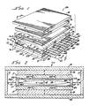
- a discharge amplification section generally designated 10A, of a laser apparatus.
- the section 10A is formed as an envelope, in the form of a generally box-like rectangular sandwich configuration including two facing surfaces 16 and 18 which are closely spaced relative to their width and length surface dimensions. The surfaces are sufficiently electrically insulating to perform the functions which will be discussed later.
- Preferred materials for surface 16A and 18A are porcelain, ceramic or glass.
- Surfaces 16A and 18A are backed by plates 12 and 14 respectively. These plates provide structural support for surfaces 16A and 18A and therefore could be made of any suitable structural material, including possibly the same material as surface 16A and 18A (such as glass). However, since it is desirable for plates 12 and 14 to also thermally conduct heat, it is desirable for these plates to be of metal. In a preferred embodiment, plates 12 and 14 are made of a ferromagnetic material such as steel, for reasons to be explained later.
- the plate-like members 12 and 14 are illustrated as being formed of a material which has an adequately high thermal conductivity and which is sufficiently thick for the formation therein of thermal cooling channels.
- Thermal cooling channels 34A and 34B are formed in plate 12, and channels 37A and 37B are formed in plate 14. Tubes, not shown, are connected to these cooling channels and a cooling liquid is circulated through these openings so as to cool plates 12 and 14. In this manner, through thermal conduction, surfaces 16 and 18, which form a major portion of the walls of the cavity 24, are cooled.
- the volume of cavity 24A is filled with a gas, which in this example is a carbon dioxide, nitrogen and helium mixture.
- Suitable magnetic field producing means are provided by permanent magnets 26 and 28.
- the magnets 26 and 28 are arranged and positioned with the polarity aligned in a direction generally perpendicular to the plane of the plates 12 and 14. That is, as shown in Figures 1 and 2, the north pole of the lower magnet 28 abuts the plate 14, while the south pole of the upper magnet 26 abuts the surface of plate 12. These polarities are shown by conventional designations "N" and "S” marked on the magnets 26 and 28 in the drawings.
- the arrow #42 in Figure 2 indicates the magnetic field direction.
- the magnets 26 and 28 preferably have a size or dimension approximating the size or dimension of the plate-like members 12 and 14 for the sake of easiest magnetic field generation.
- the magnets 26 and 28 are permanent magnets which may be formed of relatively inexpensive barium iron oxide ceramic materials, or the like. It is to be understood that other devices may be used for generating the required magnetic field such as other permanent magnets, DC electromagnets or AC electromagnets.
- the objective is to generate a field within cavity 24A with at least a major vector component perpendicular to the surfaces 16A and 18A. If the magnetic field produced by the magnets 26 and 28 needs to be made more uniform, it has been found that making plates 12 and 14 from steel helps to make the magnetic field very uniform.
- steel plates 30, 31, 32, 33 ( Figure 2) form a generally rectangular tube and surround the magnets and other parts of the struture. Plates 31 and 33 are not shown in Figures 1, 3 and 4, (to better illustrate the other components) but plates 31 and 33 are generally the same length as 30.
- This ferromagnetic tubular structure (shown rectangular, but other shapes can be used) forms a magnetic circuit giving a low magnetic reluctance path for the magnetic lines which emanate from the north pole of 26 and enter the south pole of 28.
- This magnetic circuit is part of a preferred embodiment, but not absolutely necessary to the function of the invention because the function of the magnetic circuit is to minimize the size and expense of the magnets 26 and 28, as well as confine the magnetic field to structure 10A. Eliminating plates 30, 31, 32, and 33 would require magnets 26 and 28 to be much stronger.
- the side wall members 20 and 22 are preferably formed of a suitable non-magnetic material. Wall members 20 and 22 should also be electrically insulated from each other. These side wall members maintain the spacing between surfaces 16A and 18A, and support the electrode structure, which includes first and second sets of electrodes. These sets of electrodes are generally designated 36 and 38, with electrodes of each set bearing supplementary letter suffix designations, i.e., 36A, 36B, etc.
- the set 36 of electrodes are depicted as being generally parallel, equally spaced rod-type electrodes, arranged in parallel with one another, and extending through and supported by, side wall member 20.
- electrode set 38 includes electrodes which are generally parallel to one another and in axial alignment with the corresponding electrode of set 36.
- the electrode set 38 extends through and is supported by side wall member 22. However, the electrodes do not make electrical contact through side wall members 20 and 22. It is to be understood that the electrodes depicted here are examples only. Within the general objective of forming two elongate electrode regions, there is great flexibility as to the electrode design. In particular, if the set 36 of electrodes are negatively charged cathodes operating at certain gas pressures, then larger surface area electrodes may be substituted.
- each set 36 and 38 extend into the cavity 24A for the same distance and that they are used to form an electric field designated 39.
- the electrode 40 is representative of single or multiple electrodes used to initiate the electrical discharge. This function will be discussed later.
- the electrodes are provided with suitable ballast devices such as resistors.
- Resistors 46A-46L are coupled in series with electrodes 36A-36K respectively, while resistors 48A-48L are coupled in series with electrodes 38A-38K and 40 respectively.
- the resistors designated 46 have the other ends thereof coupled together for electrical connection to a terminal 50 of a suitable power source.
- Resistors designated 48 likewise have the other ends thereof coupled together for electrical connection to the other terminal 52 of the power source. In this illustration, terminal 50 is negatively charged and terminal 52 is positively charged.
- the electrical and magnetic polarities used are examples only.
- resistors 46A-46L and 48A-48L define elongated electrode regions. It may also be possible to replace the multiple linear array of electrodes 36A-36K or 38A-38F with a single electrode, such as a rod made of a suitable electrical conductor. For optimum performance, the rod electrode should be placed so that it approximately passes through the points in space defined by the tips of electrodes 36A-36K, thereby extending over the same elongated electrode region. Similarly, another rod may be used to replace multiple electrodes 38A-38K. These rod electrodes should be connected to the positive and negative terminals of the power source respectively. It is to be understood that the optimum electrode configuration can be determined experimentally by those skilled in the art.
- the laser mirrors 54 and 56 are shown adjacent to opposite ends of the cavity 24A. These mirrors are shown as a point of reference only. The preparation of mirrors optimized for this rectangular geometry is within the capabilities of persons skilled in the art. Alternatively, the ends of the cavity 24A could be closed with totally transparent windows positioned at the locations of mirrors 54 and 56. An externally generated laser beam may be passed through the windows so as to be amplified by the amplifier section 10A. In any event, it is to be understood that the cavity 24A is suitably sealed to act as an envelope containing the gas mixture therein.
- a direct current power source is connected to terminals 50 and 52, with terminal 52 being positive.
- the direction of the magnetic field generated by magnets 26 and 28 is as indicated by the pole designations shown in Figures 1 and 2.
- the close proximity of electrode 40 to electrode 36A rapidly initiates an electrical discharge at the end of the cavity 24A where the action of the magnetic field results in continuous generation of new discharges.
- the electric field 39 creates transverse electrical discharge 58A-58K between the various other electrodes of the first and second sets electrodes (36,38)
- the action of the magnetic field is such as to exert a force on the discharge.
- the action of the magnetic field is to cause these discrete discharges to sweep in the direction indicated by the arrows 55 shown in Figure 3. This condition can be termed "discrete moving discharges".
- the discrete discharges merge into one merged homogeneous discharge, such as 58Z depicted in Figure 4.
- the dashed lines 58Z in Figure 4 represent an estimate of the general paths taken by electrons in electric field 39 when the condition of merged homogeneous discharge has been reached. This will be referred to as "Macken discharge".
- the general name which includes both the "discrete moving discharge” and the "Macken discharge” is a sweeping discharge because in both discharge conditions, the electrons are swept sideways by the action of the magnetic field.
- V 125 B/P (Equation 1) where: V is the velocity of the discharge in cm/sec.; B is the strength of the magnetic field in gauss P is the total gas pressure in torr.
- the magnetic force acts primarily on the electrons in the electrical discharge. This is because the electrons are moving many times faster than the much heavier ionized atoms and molecules.
- Equation 1 gives a general formula for the velocity of moving discharges in a CO2 laser gas.
- a reasonable condition for defining the minimum magnetic field for the claimed effect in a 1cm separation cavity is 0.0008T (80 gauss). While 80 gauss will not necessarily produce a uniform thermal heating of the gas, 80 gauss does produce a distinct thermal wake left behind moving discharges for a CO2, N2, He gas mixture. In other, yet untested, gases the constants will differ, but also from experiments, 80 gauss is considered to be a good standard for the initiation of the effect.
- the Macken discharge condition starts at a higher magnetic field which depends on many factors. These factors include: gas pressure, current density, cavity configuration and electrode configuration. The required threshold magnetic field needs to be determined experimentally.
- the maximum suitable magnetic field strength can reasonably be set at the saturation flux density of iron which is about 2.2T (22,000 gauss).
- the gas pressure was initially about 18 torr for a standard laser mix of carbon dioxide, nitrogen and helium.
- the discharge voltage was 1,800 volts at a current of about 1 amp.
- the resistors 46 were 20,000 ohms each and resistors 48 were 10,000 ohms each.
- the discharges were found to have completely merged as indicated by monitoring the current across an individual resistor, such as resistor 48E. Also, visual inspection revealed good uniformity.
- the magnetic field strength was reduced to 0.075T (750 gauss) by removing a magnet layer corresponding to magnet 26 in Figure 1 (forming a structure analagous to Figure 8), the discharge was found to still be completely uniform.
- the electrode 40 is closer spaced to the oppositely charged electrodes rather than the other electrodes in group 38. Ths electrode 40 is representative of launcher electrodes. Optional ballast resistor 48L is provided in this electrode. It is also possible to eliminate electrode 40 and to generate the necessary electric field strength to initiate new discharge between electrodes 38A and 36A. To do this, the power supply voltage and the ballast resistor size must be sufficient to initiate a discharge when current stops flowing to anode 38A.
- alternating current power may be applied at terminals 50 and 52, in which event it may be necessary to have launcher electrodes similar to electrode 40 at each end of the structure.
- the electrodes may also be positionsed at opposite ends in non-interference with the optics. In this case, the direction of electrical discharges would change by 90 degrees, but electrical discharges would still flow in a direction perpendicular to the applied magnetic field.
- electromagnets may replace the permanent magnets, with multi-phase AC power applied thereto to generate moving magnetic fields.
- Open loop discharges generally have electric field equipotential lines that leave the cavity without closing on themselves.
- the electric field arrows 39 are the electric field gradient, also known as the electric field vector.
- the equipotential lines are perpendicular to the electic field vector.
- closed loop discharges There is another group of sweeping discharges known as "closed loop discharges". These are depicted in Figures 5 and 6.
- the closed loop discharges do not need continuous initiation of new discharges.
- the discharges sweep around a closed loop forming the equivalent of an infinitely long open loop system.
- the electric field equipotential lines also form closed loops inside the cavity in this type of structure.
- FIG. 5 and 6 taken together, there is shown an alternate embodiment in which coaxial, cylindrical geometry is used rather than the planar parallel geometry of Figures 1 through 4.
- the cylindrical cavity 24T is bounded by two coaxial surfaces 16T and 18T corresponding to surface 16 and 18 in Figures 1-4.
- Surfaces 16T and 18T are relatively closely spaced compared to the circumference and axial dimensions.
- Surfaces 16T and 18T are sufficiently electrically insulating so that an electrical discharge would tend to pass through the gas contained in cavity 24T.
- Inside surface 18T there are axially aligned and spaced ferro-magnetic cylinders 32A, B, C, as shown in Figure 5.
- ferro-magnetic cylinders are magnetized by permanent magnets 26T and 28T in axial alignment therewith in the spaces there between.
- the magnets 26T and 28T are positioned with repelling polar orientation, as shown at either end of 32B.
- the magnetic field 42T for these magnets is shown in Figure 5.
- magnetic cylinder 32B serves as the south pole of the magnet over its length
- cylinders 32A and 32C serve as the north pole of the magnet over their entire length.
- cylinder 30T is a ferro-magnetic cylinder which runs the length of cylinder 16T except for appropriate openings to allow for terminals 50T and 52T which are connected to electrodes 36T and 38T.
- Cylinder 30T serves a dual purpose since it forms a part of the magnetic circuit which connects the south pole of the cylinder 32B to the north pole of cylinders 32A and 32C and it is also part of the cooling.
- the radially extending arrows 42T in Figure 5 and other unmarked arrows inside the cavity 24T in both Figures 5 and 6 indicate the local direction of the magnetic field extending between cylinders 32A, 32B, and 32C and the outside cylinder 30T shown in Figure 6. This magnetic field is analagous to magnetic field 42 in Figure 1 to 4.
- arrows 39T show the broad area electric field analagous to 39 in Figures 2 to 4.
- cylinder 30T includes four water cooling tubes 71-74, inclusive, which make thermal contact with this metallic cylinder. These tubes are representative of a cooling method which may be employed for cooling surface 16T. In this case, there would be thermal conduction from the cooled tubes 71-74 through the cylinder 30T and, ultimately, to the surface 16T.
- the inside metallic cylinders 32A, 32B and 32C are cooled by tubes 75-78 shown in Figure 6.
- This cooling method is an example only. Many other cooling methods are possible. Also, in cases such as intermittant operation, no liquid cooling may be required.
- a voltage is applied to terminals 50T and 52T, a broad area electric field 39T and an electrical discharge 58T is established through the cavity 24T between electrodes 36T and 38T.
- These electrodes are analogous to the 36 series and 38 series electrodes, therefore they can also be segmented and are considered elongated electrode regions.
- the radial magnetic fields cause the discharge to rapidly rotate. If the magnetic field is sufficiently strong, the discharge 58T will form a circle when viewed from the angle shown in Figure 6.
- the discharge can become a Macken discharge similar to the process previously described for the parallel geometry described in conjunction with Figure 4.
- Reference texts 1 and 2 Of particular interest in reference texts 1 and 2 is the information dealing with the breakdown voltage gradient, the voltage-current curve, and the requirements for stabilizing a convention discharge. References 3 and 4 deal with general effects of a magnetic field on an electrical discharge.
- the co-operative feature of these four elements is especially important in achieving a Macken discharge. It is possible to adjust the parameters of some of the elements to compensate for less than ideal conditions on other elements.
- the cavity shape and the electrodes together control the electric field shape.
- the electric field shape must at least permit the formation of a broad area sweeping discharge, but ideally, through the use of multiple ballasted electrodes and careful shaping, the electric field should encourage the spreading of the electric discharge.
- inadequacies in this ideal can be offset by increasing the magnetic field strength or an adjustment in the gas composition or pressure.
- optional thin metallic cylindrical surfaces 66 and 67 are placed in contact with the inside of surface 16T at the positions adjacent to magnets 26T and 28T, respectively.
- These cylinders 66 and 67 serve as electrodes and provide one means for the rotating electric discharges to deal with the anomaly that occurs when the direction of the magnetic field is being reversed, for example, between cylinders 32C and 32B.
- this electrical discharge would terminate on the near surface of electrode 66.
- the discharge would then re-emerge on the other end of electrode 66 and be rotating counter clockwise as the discharge passed through the region near cylinder 32B.
- the discharge would then terminate on the near edge of electrode 67 and reappear on the far side of the electrode 67, once more rotating clockwise and terminating in electrode 38T.
- Figures 1-6 show the major design philosophy, there are variations which are possible.
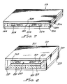
- Figures 7 and 8 show design variations to the magnetic circuit used in Figure 2 so as to supply a magnetic field to a generally rectangular cavity similar to that shown in Figures 1-4.
- Figure 7 shows only the parts which form the magnetic circuit components of the structure and a few other components needed for clarity. It does not show any of the electrodes, wires, cooling, discharge, etc., which do not form part of the magnetic circuit.
- the numbering corresponds to comparable components in Figures 1, 2 and 3 except that the letter "M" is added after the number. Therefore, the cavity 24M is formed between relatively closely spaced facing surfaces 16M and 18M.
- Support members 20M and 22M form walls of the cavity.
- Ferromagnetic (preferably steel) plate 30M performs the function of both plates 30 and 12 in Figure 2.
- plate 32M performs the function of plates 32 and 14 in Figure 2.
- Magnets 28M and 26M are placed between ferromagnetic plates 30M and 32M.
- the ferromagnetic plates transfer the magnetic field generated by said magnets and distributes relatively evenly the magnetic field in cavity 24M, with the magnetic field vector shown by 42M. Note that this structure does reverse the direction of the magnetic field vector inside the cavity compared to Figure 2, even though both figures are depicted with the north pole of the magnet up.
- the cavity dimension in the direction of the magnetic field vector is shown as being generally the same as the magnet dimension in the magnetized direction. If it is desired to make the magnet thicker or thinner than the cavity, it is possible to either machine plates 30M and 32M to accommodate the height difference. Alternatively, the magnets may be placed alongside of plates 30M and 32M with the use of steel plates as magnetic coupling elements to transfer the magnetic field into plates 30M and 32M.
- Figure 8 also shows only the elements of the structure related to the magnetic circuit.
- Figure 8 is very similar to Figure 2.
- the numbering of comparable parts is the same except for the use of the letter "P".
- the major exceptions are that magnet 26 and plate 12 have been elimated.
- the dielectric surface 16P has been placed directly on plate 30P.
- plate 14P could be made of any structurally suitable material.
- steel is the preferred material since steel also has the property of making the magnetic field in cavity 24P very uniform. Note that if steel is used for 14P, there should be a suitable gap between 14P and 33P or 31P to prevent a magnetic "short circuit".
- the magnetic circuits described in Figures 1 to 8 have the same basic elements and purpose.
- the fundamental purpose is to: 1) establish a low reluctance (high permeability) path between the two poles of a magnet with (ideally) the only gap in the path being the cavity and the non magnetic materials associated with the cavity; 2) uniformly distribute the magnetic field in the cavity and orientate it generally perpendicular to the facing surfaces; 3) establish a sufficiently strong magnetic field in the cavity.
- all of the magnetic circuit designs include: 1) at least one magnet; 2) a cavity; 3) ferromagnetic pieces backing the relatively closely spaced facing surfaces of the cavity; 4) no major magnetic "short circuiting" connection to the ferromagnetic backing pieces which would substantially reduce the magnetic field in the cavity; 5) a magnetic circuit design which provides a ferromagnetic return path as needed to complete the magnetic circuit. From the teachings presented here, it is possible to make a variety of magnetic circuits including stacked, multi cavity laser structures.
- a cylindrical geometry could be made which would be analagous to wrapping the planar geometry cavity depicted in Figure 3 into a cylindrical geometry, with the cylindrical axis being parallel to the arrows shown on the discharges 58C and 58E.
- another configuration would comprise cylindrical geometry which eliminates magnets 26T and 28T in Figure 5. This could be achieved by replacing them with cylindrical magnets which would be placed in the space between cylinders 30T and 16T in Figure 6. These cylindrical magnets would be radially magnetized with periodically reversed polarity to produce the same type of magnetic field distribution in the cavity as is depicted in Figures 5 and 6.
- ferromagnetic cylinders 32A, 32B, and 32C with one continuous ferromagnetic cylinder.
- Figures 5 and 6 are representative of a class called “closed loop discharge apparatus.”
- Figures 1-4 are representative of a class called “open loop discharge apparatus.”
- closed loop discharge apparatus Several variations on the closed loop discharge exist. For example, it is possible to combine two structures similar to Figure 7 with one placed one on top of the other. They would be oriented with the same magnetic polarity on the middle plate between the two cavities and the middle plate would also have a complete dielectric coating. With an external envelope to maintain the partial vacuum, it would be possible for the discharge to form a continuous loop by first sweeping through the top cavity then flipping into the bottom cavity to complete the loop.
- the rectangular cavity has three dimensions which will be called: (e), parallel to the electric field; (b), parallel to the magnetic field; and (s), parallel to the sweeping direction.
- (b) is much smaller than (e)
- (e) is smaller than (s).
- these dimensions can follow cavity contours.
- the electric discharge has no problem being stabilized in the (e) direction, as long as some ballasting means are provided to limit the current within the gas.
- the electric discharge even moves around charged particles creating space charges and local voltage gradients as needed to form a stable condition in the (e) direction.
- the size of the cavity and the pressure of the gas have been chosen to stablize the discharge. This form of stabilizaion is commonly referred to as "wall stabilization.”
- the (s) dimension is chosen to be large.
- the electric field is usually a fairly uniform potential parallel to the (s) direction. Without any other means of dispersing the discharge in the (s) direction, the discharge will assume a width in the (s) direction roughly equal to the (b) dimension. This forms a fairly round discharge which will usually wander around in the (s) dimension.
- the restriction in the size of the discharge in the (s) dimension is believed to be because the heating of the gas lowers the discharge voltage gradient in a narrow channel. This is referred to as thermal confinement of the discharge.
- the objective is to introduce a new force in the (s) dimension to overcome this thermal confinement.
- a magnetic field is used to introduce this force on the discharge. For example, it has been calculated that at about 80 gauss for a 1cm cavity in the (b) direction, the force becomes sufficient to move the discharge through the gas at a rate where the discharge moves one wall separation distance (b) in a time equal to the thermal time constant of the gas. This condition still exhibits thermal confinement, but the effectss have been reduced.
- a pulsed ultra violet laser with a cylindrical tube which contains two parallel elongated electrode regions extending down the length of the cylinder and generally located near the cylinder walls being opposite each other across the axis of the cylinder. These two elongated electrode regions form a broad area electric field with the magnetic field extending perpendicular to the electric field vector and the length of the cylinder.
- the pulsed power supply energizing these electrodes could provide the needed electrical excitation.
- two facing surfaces does not necessarily mean that there has to be a physical break between these surfaces. Also, it is to be understood that the addition of multiple layers or levels of cavities with “two facing surfaces” in each layer or level does not constitute a departure from the invention.
- the facing surfaces should be sufficiently electrically insulating that an applied voltage parallel to the surfaces produces an electric discharge through the gas.
- segmented electrically conductive pieces can be used for a discharge cavity if they are cut up in short enough lengths and electrically insulated from each other. These pieces are an example of being “effectively electrically insulating” because they are electrically insulating to the electrical discharge.
- the portion of the magnetic field vector component which is parallel to the median has an undesirable effect and is a waste of magnetic field strength, but it can be tolerated.
- the term "magnet” is use to denote any source of magnetic field including permanent magnets and electro magnets. The use of permanent magnets in the examples is only an illustration.
- the term “magnetic circuit” and “short circuit” are both making analogies with electrical circuits.
- the use of ballast resistors or "ballast” is to be understood as being representative of any current limiting means, such as ballast tubes, transistors or current limited power supplies. Even a cathode run at current densities called the "abnormal glow" exhibit a type of distributed ballasting. Even a single elongated electrode could conceivably have a resistive layer producing the equivalent effect of multiple ballasted electrodes.
Landscapes
- Physics & Mathematics (AREA)
- Electromagnetism (AREA)
- Engineering & Computer Science (AREA)
- Plasma & Fusion (AREA)
- Optics & Photonics (AREA)
- Health & Medical Sciences (AREA)
- Toxicology (AREA)
- Lasers (AREA)
Claims (28)
- Gaslaser-Vorrichtung (10) mit einem Resonator (24), wobei der Resonator (24) begrenzt oder teilweise begrenzt ist durch zwei sich gegenüberliegende Oberflächen (16, 18), die relativ eng beabstandet sind, wobei die Gaslaser-Vorrichtung gekennzeichnet ist durch das Vorhandensein von Elektrodeneinrichtungen (36, 38) zum Herstellen eines elektrischen Feldes (39), wobei die Elektrodeneinrichtungen langgestreckt sind, und einer elektrischen Entladung (58) in dem Resonator (24), wobei die Ausrichtung des elektrischen Feldes (39) im wesentlichen parallel zu den sich gegenüberliegenden Oberflächen (16, 18) ist, und durch das Vorhandensein einer Einrichtung (26, 28) zum Herstellen eines Magnetfeldes (42) in dem Resonator (24) mit mindestens einer Hauptvektorkomponente, die im wesentlichen rechtwinklig zu den sich gegenüberliegenden Oberflächen (16, 18) ist, wobei die elektrische Entladung (58) in Betrieb Zu einer Wobbelentladung zwischen den beiden sich gegenüberliegenden Oberflächen wird, wobei die Wobbelentladung sich über eine Entfernung ausbreitet, die im wesentlichen größer ist als der Abstand zwischen den sich gegenüberliegenden Oberflächen (16, 18).
- Gaslaser-Vorrichtung (10) nach Anspruch 1, ferner dadurch gekennzeichnet, daß die Einrichtung (26, 28) zum Erzeugen des Magnetfeldes (42) ein Magnetfeld mit einer Stärke erzeugt, die größer ist als eine Stärke, die erforderlich ist, damit sich diskrete, sich bewegende Entladungskomponenten (58A, 58C, 58E) der Wobbelentladung (58) über eine Entfernung bewegen, die gleich dem Abstand zwischen den sich gegenüberliegenden Oberflächen (16, 18) ist in einer Zeit, die gleich der thermischen Zeitkonstante eines Gases zwischen den sich gegenüberliegenden Oberflächen (16, 18) ist.
- Gaslaser-Vorrichtung (10) nach Anspruch 1, ferner dadurch gekennzeichnet, daß die Einrichtung (26, 28) zum Erzeugen des Magnetfeldes ein Magnetfeld (39) mit einer ausreichenden Stärke erzeugt, um mindestens einen wesentlichen Teil der Wobbelentladung (58) in eine im allgemeinen gleichmäßige Entladung (58Z, 58T) einzumischen.
- Gaslaser-Vorrichtung (10) nach Anspruch 2, ferner dadurch gekennzeichnet, daß die Einrichtung (26, 28) zum Erzeugen des Magnetfeldes ein Magnetfeld im Bereich von 0,008 Tesla bis 2,2 Tesla (80 Gauß bis 22.000 Gauß) erzeugt.
- Gaslaser-Vorrichtung (10) nach einem der vorangegangenen Ansprüche, ferner gekennzeichnet durch das Vorhandensein von Einrichtungen (34, 37, 71 bis 78) zum Kühlen mindestens einer der sich gegenüberliegenden Oberflächen (16, 18), wobei die Einrichtungen zum Kühlen (34, 37, 71 bis 78) eine Primäreinrichtung zum Kühlen von Gas in dem Resonator (24) darstellen, der durch die elektrische Entladung (58) erwärmt wird.
- Gaslaser-Vorrichtung (10) nach einem der vorangegangenen Ansprüche, ferner dadurch gekennzeichnet, daß die Oberflächen (16, 18) wirksam elektrisch isoliert sind.
- Gaslaser-Vorrichtung (10) nach einem der vorangegangenen Ansprüche, ferner dadurch gekennzeichnet, daß die Elektrodeneinrichtungen (36, 38) mindestens zwei langgestreckte Elektrodenbereiche aufweisen, wobei jeder der langgestreckten Elektrodenbereiche eine Gruppe von zwei oder mehr Elektroden aufweist, wobei mindestens eine Elektrode (40) einer Gruppe und eine benachbarte Elektrode (36A) einer anderen Gruppe Enden aufweisen, die ein enger beabstandetes Verhältnis zueinander haben, als es die Enden der übrigen der einen Gruppe mit den Enden der übrigen der anderen Gruppe haben, wodurch die Auslösung der elektrischen Entladung (58) erleichtert wird.
- Gaslaser-Vorrichtung (10) nach einem der Ansprüche 1 bis 7, dadurch gekennzeichnet, daß die Elektrodeneinrichtungen (36, 38) mindestens zwei Elektroden in dem Resonator (24) aufweisen, die zwei langgestreckte Elektrodenbereiche bilden, und ferner gekennzeichnet durch Widerstandseinrichtungen (46, 48), die mindestens zu einer Elektrode gehören, um die elektrische Entladung (58) über einen wesentlichen Teil mindestens eines der langgestreckten Elektrodenbereiche (36, 38) zu verteilen.
- Gaslaser-Vorrichtung (10) nach einem der vorangegangenen Ansprüche, ferner dadurch gekennzeichnet, daß die Elektrodeneinrichtungen zum Erzeugen des elektrischen Feldes im wesentlichen sich nicht umkehrende Polarität aufweisen und dadurch im wesentlichen eine elektrische Gleichstromladung (58) erzeugen.
- Gaslaser-Vorrichtung (10) nach einem der vorangegangenen Ansprüche, ferner dadurch gekennzeichnet, daß die Elektrodeneinrichtungen zum Erzeugen des elektrischen Feldes Äquipotentiallinien aufweisen, die in dem Resonator (24) geschlossene Kreise bilden.
- Gaslaser-Vorrichtung (10) nach einem der Ansprüche 1 bis 9, ferner dadurch gekennzeichnet, daß die Elektrodeneinrichtungen zum Erzeugen des elektrischen Feldes Äquipotentiallinien aufweisen, die in dem Resonator (24) offene Kreise bilden, wobei ein Gradient des elektrischen Feldes ausreicht zum Beibehalten einer kontinuierlichen Auslösung von elektrischen Entladungen (58) in dem Resonator (24).
- Gaslaser-Vorrichtung (10) nach einem der vorangegangenen Ansprüche, ferner dadurch gekennzeichnet, daß die sich gegenüberliegenden Oberflächen (16, 18) im wesentlichen ebene und parallele Oberflächen mit im wesentlichen gleichen Oberflächenabmessungen sind.
- Gaslaser-Vorrichtung (10) nach einem der Ansprüche 1 bis 11, ferner dadurch gekennzeichnet, daß die Oberflächen (16T, 18T) im wesentlichen zylindrisch sind und koaxial positioniert sind.
- Gaslaser-Vorrichtung (10) nach Anspruch 1, ferner dadurch gekennzeichnet, daß der Resonator (24) eine zylindrische Röhre (24T) ist und die Elektrodeneinrichtungen (36, 38) derartig positioniert sind, daß ein elektrisches Feld (39T) hergestellt wird, das im allgemeinen parallel zu der Achse des Zylinderröhrenresonators (24T) ist.
- Gaslaser-Vorrichtung (10) nach einem der vorangegangenen Ansprüche, ferner dadurch gekennzeichnet, daß die Einrichtung (26T, 28T) zum Herstellen eines Magnetfeldes mindestens einen Magneten zusammen mit einem entsprechend positionierten ferromagnetischen Material (mit der Folge 30, 31, 32, 33, 12, 14) aufweist, um einen Magnetkreis zu bilden, der das Magnetfeld in dem Resonator (24T) verteilt.
- Gaslaser-Vorrichtung (10) nach Anspruch 15, ferner dadurch gekennzeichnet, daß der Magnetkreis eine ferromagnetische, im wesentlichen röhrenförmige Struktur (30, 31, 32, 33 und 30P, 31P, 32P, 33P) aufweist, die mindestens den einen Magneten (26, 28, 28P) und den Resonator (24, 24P) umgibt.
- Gaslaser-Vorrichtung (10) nach Anspruch 15, ferner dadurch gekennzeichnet, daß der Magnetkreis mindestens zwei konzentristhe ferromagnetische Zylinder (32A, 30T) aufweist, wobei mindestens ein Teil des Resonators (24T) mindestens in einem Teil des Volumens zwischen den konzentrischen Zylindern (32A, 30T) angeordnet ist.
- Gaslaser-Vorrichtung (10) nach einem der vorangegangenen Ansprüche, ferner dadurch gekennzeichnet, daß die Einrichtung zum Herstellen eines Magnetfeldes einen oder mehrere Dauermagneten aufweist.
- Verfahren zum Herstellen einer elektrischen Entladung auf einer im wesentlichen gleichmäßigen, breiten fläche, mit den folgenden Schritten:
Bereitstellen eines gasgefüllten Resonators (24) zwischen zwei relativ eng beabstandeten Oberflächen (16, 18); Bereitstellen von Elektrodeneinrichtungen (36, 38), wobei die Elektrodeneinrichtungen langgestreckt sind; und
Bereitstellen eines Magnetfeldes (42) in einer Richtung, die im wesentlichen rechtwinklig zu den Oberflächen (16, 18) ist; wobei das Verfahren dadurch gekennzeichnet ist, daß es ferner folgendes aufweist:
Bereitstellen mindestens einer elektrischen Entladung (58) in dem gasgefüllten Resonator (24), der mit einem elektrischen Feld (39) im wesentlichen parallel zu den sich gegenüberliegenden Oberflächen (16, 18) ausgerichtet ist, damit das Magnetfeld auf die elektrische Entladung reagieren und eine im allgemeinen stabile elektrische Wobbelentladung erzeugen kann, die sich quer zu dem elektrischen Feld über eine Entfernung ausbreitet, die im wesentlichen größer ist als der Abstand zwischen den sich gegenüberliegenden Oberflächen (16, 18), wodurch eine elektrische Entladung auf einer im wesentlichen gleichmäßigen, breiten Fläche (58Z, 58T) erzeugt wird. - Verfahren nach Anspruch 19, ferner dadurch gekennzeichnet, daß der Schritt des Bereitstellens einer breitflächigen elektrischen Entladung (58Z, 58T) die Positionierung der Elektroden (36, 38) in dem Resonator (24) und das Anlegen elektrischer Leistung an die Elektroden (36, 38) aufweist.
- Verfahren nach Anspruch 20, ferner dadurch gekennzeichnet, daß der Schritt des Herstellens eines Magnetfeldes das Unterstützen mindestens einer der sich gegenüberliegenden Oberflächen (16, 18) mit ferromagnetischem Material (12, 14, 30, 32) und das Positionieren mindestens eines Magneten (26, 28) in der Nähe mindestens eines Teils des ferromagnetischen Materials 12, 14, 30, 32) einschließt.
- Verfahren nach einem der Ansprüche 19 bis 21, ferner dadurch gekennzeichnet, daß die Oberflächen (16, 18) im wesentlichen elektrisch isolierend, eben, parallel und eng beabstandet in bezug auf die Oberflächenabmessungen sind.
- Verfahren nach einem der Ansprüche 19 bis 21, ferner dadurch gekennzeichnet, daß erreicht wird, daß die Oberflächen (16T, 18T) im wesentlichen elektrisch isolierend, im wesentlichen zylindrisch und im wesentlichen koaxial und eng beabstandet in bezug auf die Abmessungen sind.
- Verfahren nach Anspruch 23, ferner gekennzeichnet durch den Schritt des Bereitstellens einer breitflächigen elektrischen Entladung (58T) einschließlich des Positionierens von mindestens zwei Elektrodenringen (36T, 38T) koaxial mit den Oberflächen (16T, 18T).
- Verfahren nach einem der Ansprüche 19 bis 24, ferner gekennzeichnet durch den Schritt des Abkühlens mindestens einer der Oberflächen (16, 18).
- Verfahren nach Ansprüche 24, ferner dadurch gekennzeichnet, daß der Schritt des Bereitstellens eines Magnetfeldes (42T) das Positionieren mindestens eines Magneten (26T, 28T) und mindestens eines ferromagnetischen Zylinders (32A,B,C, 30T) hinter mindestens einer der Oberflächen (16T, 18T) einschließt, um ein radiales Magnetfeld (42T) herzustellen.
- Verfahren nach Anspruch 20, wobei der Schritt des Positionierens der Elektroden ferner gekennzeichnet ist durch das Ausbilden von zwei sich gegenüberliegenden langgestreckten Elektrodenbereichen (36, 38), die verteilte elektrische Widerstände (46, 48) zum Zweck des Ausbreitens der elektrischen Entladung (58) über mindestens eine wesentliche Länge mindestens eines der langgestreckten Elektrodenbereiche (36, 38) darstellen.
- Verfahren nach Anspruch 27, wobei der Schritt des Positionierens der Elektroden ferner dadurch gekennzeichnet ist, daß mindestens einer der langgestreckten Elektrodenbereiche (36, 38) eine Elektrodenkomponente (40) aufweist, die ein enger beabstandetes Verhältnis zu dem umgekehrt geladenen Elektrodenbereich (36) hat, wodurch das Auslösen der elektrischen Entladung (58Z) erleichtert wird.
Applications Claiming Priority (2)
| Application Number | Priority Date | Filing Date | Title |
|---|---|---|---|
| US71545885A | 1985-03-25 | 1985-03-25 | |
| US715458 | 1985-03-25 |
Publications (3)
| Publication Number | Publication Date |
|---|---|
| EP0196218A2 EP0196218A2 (de) | 1986-10-01 |
| EP0196218A3 EP0196218A3 (en) | 1988-11-30 |
| EP0196218B1 true EP0196218B1 (de) | 1993-10-27 |
Family
ID=24874134
Family Applications (1)
| Application Number | Title | Priority Date | Filing Date |
|---|---|---|---|
| EP19860302206 Expired - Lifetime EP0196218B1 (de) | 1985-03-25 | 1986-03-25 | Laser-Vorrichtung und Verfahren |
Country Status (3)
| Country | Link |
|---|---|
| EP (1) | EP0196218B1 (de) |
| CA (1) | CA1259396A (de) |
| DE (1) | DE3689201T2 (de) |
Families Citing this family (2)
| Publication number | Priority date | Publication date | Assignee | Title |
|---|---|---|---|---|
| IL82545A (en) * | 1987-05-15 | 1991-11-21 | Galram Technology Ind Ltd | Method and apparatus for the cooling of gas lasers |
| CN102118006B (zh) * | 2009-12-30 | 2012-06-27 | 杭州中科新松光电有限公司 | 一种大功率气体激光器光腔真空调试工艺 |
Family Cites Families (3)
| Publication number | Priority date | Publication date | Assignee | Title |
|---|---|---|---|---|
| US3413568A (en) * | 1965-06-22 | 1968-11-26 | Bell Telephone Labor Inc | Reversed axial magnetic fields in lasers |
| FR1557756A (de) * | 1967-12-01 | 1969-02-21 | ||
| US4035741A (en) * | 1975-02-14 | 1977-07-12 | Owens-Illinois, Inc. | Magnetic polarization of tubular laser |
-
1986
- 1986-03-24 CA CA000504850A patent/CA1259396A/en not_active Expired
- 1986-03-25 EP EP19860302206 patent/EP0196218B1/de not_active Expired - Lifetime
- 1986-03-25 DE DE19863689201 patent/DE3689201T2/de not_active Expired - Fee Related
Also Published As
| Publication number | Publication date |
|---|---|
| DE3689201T2 (de) | 1994-04-21 |
| EP0196218A3 (en) | 1988-11-30 |
| DE3689201D1 (de) | 1993-12-02 |
| EP0196218A2 (de) | 1986-10-01 |
| CA1259396A (en) | 1989-09-12 |
Similar Documents
| Publication | Publication Date | Title |
|---|---|---|
| US4755999A (en) | Laser apparatus utilizing a magnetically enhanced electrical discharge | |
| US3886479A (en) | Electrode systems for gas discharge devices particularly gas lasers | |
| CA1147048A (en) | High power laser and cathode structure therefor | |
| US3743963A (en) | Transverse gas laser | |
| US3761836A (en) | Magnetically compensated cross field flowing gas laser | |
| EP0196218B1 (de) | Laser-Vorrichtung und Verfahren | |
| US4677637A (en) | TE laser amplifier | |
| US4449220A (en) | Apparatus and method for deposition of electrical power in an electric discharge laser | |
| Myshenkov et al. | Prospects for using high-frequency capacitative discharges in lasers | |
| US3747015A (en) | Magnetic stabilized cross field flowing gas laser | |
| JPH0671108B2 (ja) | 磁気的に高められた放電を利用するレ−ザ−装置 | |
| Targ et al. | High-repetition-rate xenon laser with transverse excitation | |
| Shi et al. | Experimental investigation on the current carried by a cathode spot of vacuum arc in axial magnetic fields | |
| GB2107512A (en) | Apparatus for producing a laser-active state in a fast subsonic flow | |
| US4910742A (en) | Method and apparatus for the cooling of gas lasers | |
| US4723255A (en) | Extended lifetime railgap switch | |
| Harry et al. | Multiple electrode system for high power CO2 laser excitation | |
| JPH0537056A (ja) | ガスレーザ発振器 | |
| US4574380A (en) | Self-optimizing electrode and pulse-stabilized super high power C.W. gas lasers | |
| CN1014664B (zh) | 气体激光放电设备和放电方法 | |
| Hall et al. | RF excitation of diffusion cooled and fast axial flow lasers | |
| JPS6335116B2 (de) | ||
| EP1176857A1 (de) | Gleichstrom-Plasmaerzeuger zur Erzeugung eines nicht-lokalen, nicht im thermodynamischen Gleichgewicht, Hochdruck-Plasmas | |
| CA1040735A (en) | Generation of corona for laser excitation | |
| US3970961A (en) | Thermionic cathode transverse-discharge gas laser tube |
Legal Events
| Date | Code | Title | Description |
|---|---|---|---|
| PUAI | Public reference made under article 153(3) epc to a published international application that has entered the european phase |
Free format text: ORIGINAL CODE: 0009012 |
|
| AK | Designated contracting states |
Kind code of ref document: A2 Designated state(s): CH DE FR GB IT LI NL |
|
| PUAL | Search report despatched |
Free format text: ORIGINAL CODE: 0009013 |
|
| AK | Designated contracting states |
Kind code of ref document: A3 Designated state(s): CH DE FR GB IT LI NL |
|
| 17P | Request for examination filed |
Effective date: 19890530 |
|
| 17Q | First examination report despatched |
Effective date: 19910911 |
|
| GRAA | (expected) grant |
Free format text: ORIGINAL CODE: 0009210 |
|
| AK | Designated contracting states |
Kind code of ref document: B1 Designated state(s): CH DE FR GB IT LI NL |
|
| PG25 | Lapsed in a contracting state [announced via postgrant information from national office to epo] |
Ref country code: NL Effective date: 19931027 Ref country code: LI Effective date: 19931027 Ref country code: FR Effective date: 19931027 Ref country code: CH Effective date: 19931027 |
|
| ITF | It: translation for a ep patent filed | ||
| REF | Corresponds to: |
Ref document number: 3689201 Country of ref document: DE Date of ref document: 19931202 |
|
| REG | Reference to a national code |
Ref country code: CH Ref legal event code: PL |
|
| EN | Fr: translation not filed | ||
| NLV1 | Nl: lapsed or annulled due to failure to fulfill the requirements of art. 29p and 29m of the patents act | ||
| PLBE | No opposition filed within time limit |
Free format text: ORIGINAL CODE: 0009261 |
|
| STAA | Information on the status of an ep patent application or granted ep patent |
Free format text: STATUS: NO OPPOSITION FILED WITHIN TIME LIMIT |
|
| 26N | No opposition filed | ||
| PGFP | Annual fee paid to national office [announced via postgrant information from national office to epo] |
Ref country code: DE Payment date: 20010319 Year of fee payment: 16 |
|
| PGFP | Annual fee paid to national office [announced via postgrant information from national office to epo] |
Ref country code: GB Payment date: 20010321 Year of fee payment: 16 |
|
| REG | Reference to a national code |
Ref country code: GB Ref legal event code: IF02 |
|
| PG25 | Lapsed in a contracting state [announced via postgrant information from national office to epo] |
Ref country code: GB Free format text: LAPSE BECAUSE OF NON-PAYMENT OF DUE FEES Effective date: 20020325 |
|
| PG25 | Lapsed in a contracting state [announced via postgrant information from national office to epo] |
Ref country code: DE Free format text: LAPSE BECAUSE OF NON-PAYMENT OF DUE FEES Effective date: 20021001 |
|
| GBPC | Gb: european patent ceased through non-payment of renewal fee |
Effective date: 20020325 |
|
| PG25 | Lapsed in a contracting state [announced via postgrant information from national office to epo] |
Ref country code: IT Free format text: LAPSE BECAUSE OF NON-PAYMENT OF DUE FEES;WARNING: LAPSES OF ITALIAN PATENTS WITH EFFECTIVE DATE BEFORE 2007 MAY HAVE OCCURRED AT ANY TIME BEFORE 2007. THE CORRECT EFFECTIVE DATE MAY BE DIFFERENT FROM THE ONE RECORDED. Effective date: 20050325 |