EP0196411A2 - Suspension hydropneumatique - Google Patents
Suspension hydropneumatique Download PDFInfo
- Publication number
- EP0196411A2 EP0196411A2 EP86100856A EP86100856A EP0196411A2 EP 0196411 A2 EP0196411 A2 EP 0196411A2 EP 86100856 A EP86100856 A EP 86100856A EP 86100856 A EP86100856 A EP 86100856A EP 0196411 A2 EP0196411 A2 EP 0196411A2
- Authority
- EP
- European Patent Office
- Prior art keywords
- housing
- articulation
- link
- lever
- swing arm
- Prior art date
- Legal status (The legal status is an assumption and is not a legal conclusion. Google has not performed a legal analysis and makes no representation as to the accuracy of the status listed.)
- Granted
Links
Images

Classifications
-
- F—MECHANICAL ENGINEERING; LIGHTING; HEATING; WEAPONS; BLASTING
- F16—ENGINEERING ELEMENTS AND UNITS; GENERAL MEASURES FOR PRODUCING AND MAINTAINING EFFECTIVE FUNCTIONING OF MACHINES OR INSTALLATIONS; THERMAL INSULATION IN GENERAL
- F16F—SPRINGS; SHOCK-ABSORBERS; MEANS FOR DAMPING VIBRATION
- F16F9/00—Springs, vibration-dampers, shock-absorbers, or similarly-constructed movement-dampers using a fluid or the equivalent as damping medium
- F16F9/10—Springs, vibration-dampers, shock-absorbers, or similarly-constructed movement-dampers using a fluid or the equivalent as damping medium using liquid only; using a fluid of which the nature is immaterial
- F16F9/14—Devices with one or more members, e.g. pistons, vanes, moving to and fro in chambers and using throttling effect
- F16F9/145—Devices with one or more members, e.g. pistons, vanes, moving to and fro in chambers and using throttling effect involving only rotary movement of the effective parts
-
- B—PERFORMING OPERATIONS; TRANSPORTING
- B62—LAND VEHICLES FOR TRAVELLING OTHERWISE THAN ON RAILS
- B62D—MOTOR VEHICLES; TRAILERS
- B62D55/00—Endless track vehicles
- B62D55/08—Endless track units; Parts thereof
- B62D55/104—Suspension devices for wheels, rollers, bogies or frames
- B62D55/112—Suspension devices for wheels, rollers, bogies or frames with fluid springs, e.g. hydraulic pneumatic
- B62D55/1125—Hydro-pneumatic or pneumatic, e.g. air-cushioned
Definitions
- the invention relates to a hydraulic pneumatic suspension according to the preamble of the claim loader according to the preamble of the independent claim 2.
- the invention has for its object to provide a hydropneumatic suspension of the type mentioned, which is characterized by the smallest possible installation space and a high level of service friendliness and with which the possible travel and the spring forces can be varied over a wide range.
- the vehicle-fixed articulation points are close to the chassis part, so that the suspension can be accommodated in the smallest space. All active suspension elements are located outside the vehicle. Even with the suspension parts lying close together, each with its own suspension, each suspension part can be supported with a relatively large spring travel. The suspension of each chassis part is easily accessible, which is favorable for the assembly and the quick replacement of damaged or defective elements.
- the handlebar parallelogram which consists of robust and few individual parts, because parts of the arc spring element form active parts of the handlebar parallelogram, the suspension characteristics and the amount of forces to be absorbed can be varied over a wide range.
- the gas spring which is housed in the chain wheel or in the swing arm, has the advantage that it cannot be accommodated inside the vehicle, where it could possibly endanger the crew of the vehicle in the event of an accident or fire.
- the measures according to claim 7 are also expedient, because in this somewhat asymmetrical configuration of the handlebar parallelogram, a translation of movement between the vehicle and the chassis part with respect to the pivoting movement of the abutment for the circular arc spring element is achieved.
- a particularly strong translation can also be achieved in the embodiment according to claim 8 if the lever lengths are designed in the manner specified.
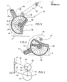
- a hydropneumatic suspension 1 can be seen from FIGS. 1 and 2, as is used, for example, in an armored vehicle for suspension of the chain wheels 18.
- An arc spring 4 is used as the active spring element, as described in the earlier patent application P 3 4 2o 557.8.
- the detailed structure of the circular arc spring element is not explained below, but reference is hereby expressly made to the content of this earlier patent application P 34 2o 557.8, as far as the structure of the circular arc spring element is concerned.
- the hydropneumatic suspension 1 serves to cushion a tank pan 2 from the floor 3, an arc spring element 4 being used as the active element, which has a round housing 5 in which a radially extending support 6 and a stop surface 7 for a rotatable around the housing axis G. , lever-shaped abutment 8 are provided.
- the abutment 8 is connected in one piece to a shaft 9 rotatable about the housing axis G.
- a spring element consisting of several segments 10, which is filled with a hydraulic fluid and cooperates with a gas spring 11, which is indicated by dashed lines in the housing 5, outside of the housing 5 or attached to it.
- a radially projecting rocker arm 12 is formed on the housing 5 and is articulated in a pivot point 13 which is firmly connected to the armored trough 2.
- a parallel link 15 is articulated to a second, higher articulation point 14 of the armored trough 2, which is offset towards the housing axis G and is connected via a joint 16 to a articulation lever 17, which in turn is integrally connected to the shaft 9 in the housing 5 is.
- the impeller 18 with bearings 21 is rotatably mounted on the shaft 9 (FIG. 2).
- the link lever 17 is non-rotatably connected to the shaft 9 by a spline 19.
- the housing 5 is rotatably mounted on the shaft 9 with the housing part 22 carrying the support 6 and the stop surface 7 with bearings 20.
- the swing arm 12 extends laterally obliquely into the interior of the impeller to the housing 5.
- the segments 10 of Figure 1 and Figure 2 form a bellows in the housing 5.
- the length of the parallel link 15 is approximately equal to the length of the swing arm 12 between the articulation point 13 and the housing axis G.
- the articulation lever 17 is approximately half as long as the swing arm 12. If the articulation lever 17 is made longer and therefore the parallel link 15 shortened, the pivoting movement of the articulation lever 17 in the clockwise direction, which occurs during deflection, will have a smaller radian measure, so that the compression of the bellows consisting of the segments 10 with the same spring travel is smaller and the spring detection thereby becomes different. Conversely, if the articulation lever 17 is further shortened, the compression of the bellows becomes stronger.
- the spring identification can also be changed by coordinating the relative positions between the joint 16 and the articulation points 13 and 14.
- an arc spring element 30 with a slightly different design is used, which has a housing 33 with the support 39 and an abutment 38 which can be rotated about the housing axis G with a shaft 37. Between the abutment 38 and the support 39, the bellows consisting of individual, hydraulically tightly connected segments 10 is again arranged.
- a radial rocker arm 34 is formed on the housing 33 and is articulated in an articulation point 31 of the armored trough 2.
- a linkage lever 35 is connected to the shaft 37 and can be bent with a pressure link 36 via a joint 40 is connected, which in turn is pivotable in a second articulation point 32 of the tank pan 2.
- the circular arc spring element 30 is in turn structurally integrated with the chain wheel 18.
- the joint 40 In the sprung position of the suspension shown in FIG. 3, the joint 40 is located on the side of the imaginary connecting line between the articulation point 32 and the housing axis G facing the swing arm 34. This means that when the spring is deflected into the position of FIG. 4, the joint 40 follows the counterclockwise pivoting movement of the swing arm 40, so that the abutment 38 is pivoted counterclockwise to the position 38 '.
- the support 39 also pivots into the position 39 '.
- a circular arc spring element 48 is arranged with its housing separate from the chain wheel 18 'in a joint 45 of the parallel linkage, which articulates the rocker arm 44 from one of the armored trough in an overhead articulation point 41, one between a housing axis 45 of the circular arc spring element 48 and a joint 47, which is also the axis of rotation of the chain wheel 18, arranged articulation lever 46, a parallel link 43 connecting the joint 47 with a lower articulation point 42 on the armored trough 2 and finally the portion of the armored trough present between the articulation points 41 and 42 2 exists.
- the swing arm 44 and the articulation lever 46 pivot about the housing axis 45 in the direction of the arrows 49 and 50 relative to one another, which movement can be used to compress the bellows, which is not emphasized. Slightly more installation space is required for this solution. However, the rotary bearing of the chain wheel 18 'and the attachment of the arc spring element 48 is easier than in the previous solutions.
- a deliberate variation in the spring detection or spring behavior can be achieved by varying the lever ratios and the relative positions of the articulation points and joints.
Landscapes
- Engineering & Computer Science (AREA)
- Mechanical Engineering (AREA)
- General Engineering & Computer Science (AREA)
- Chemical & Material Sciences (AREA)
- Combustion & Propulsion (AREA)
- Transportation (AREA)
- Vehicle Body Suspensions (AREA)
- Transition And Organic Metals Composition Catalysts For Addition Polymerization (AREA)
Priority Applications (1)
| Application Number | Priority Date | Filing Date | Title |
|---|---|---|---|
| AT86100856T ATE43544T1 (de) | 1985-04-02 | 1986-01-23 | Hydropneumatische federung. |
Applications Claiming Priority (2)
| Application Number | Priority Date | Filing Date | Title |
|---|---|---|---|
| DE19853512051 DE3512051A1 (de) | 1985-04-02 | 1985-04-02 | Hydropneumatische federung |
| DE3512051 | 1985-04-02 |
Publications (3)
| Publication Number | Publication Date |
|---|---|
| EP0196411A2 true EP0196411A2 (fr) | 1986-10-08 |
| EP0196411A3 EP0196411A3 (en) | 1988-05-25 |
| EP0196411B1 EP0196411B1 (fr) | 1989-05-31 |
Family
ID=6267123
Family Applications (1)
| Application Number | Title | Priority Date | Filing Date |
|---|---|---|---|
| EP86100856A Expired EP0196411B1 (fr) | 1985-04-02 | 1986-01-23 | Suspension hydropneumatique |
Country Status (4)
| Country | Link |
|---|---|
| US (1) | US4693492A (fr) |
| EP (1) | EP0196411B1 (fr) |
| AT (1) | ATE43544T1 (fr) |
| DE (3) | DE8509894U1 (fr) |
Families Citing this family (2)
| Publication number | Priority date | Publication date | Assignee | Title |
|---|---|---|---|---|
| DE10328541B4 (de) * | 2003-06-24 | 2009-02-05 | Rheinmetall Landsysteme Gmbh | Hydrop-Element und Verwendung in einem Fahrzeug mit Laufwerk und Laufwerksrollen |
| US7780339B2 (en) * | 2006-04-24 | 2010-08-24 | Red Devil Equipment Company | Vortex motion paint mixing machine |
Family Cites Families (5)
| Publication number | Priority date | Publication date | Assignee | Title |
|---|---|---|---|---|
| US3047283A (en) * | 1958-05-01 | 1962-07-31 | Monroe Auto Equipment Co | Fluid actuated frictional damping device |
| US3333867A (en) * | 1965-07-26 | 1967-08-01 | Gen Motors Corp | Suspension unit with parallel shock absorbers |
| SE432568B (sv) * | 1977-05-18 | 1984-04-09 | Hegglund & Soner Ab | Fjedringsanordning vid bandfordon |
| US4171830A (en) * | 1978-03-02 | 1979-10-23 | Granning Suspensions, Inc. | Vehicle suspension lift system |
| DE3420557A1 (de) * | 1984-06-01 | 1985-12-12 | Ficht GmbH, 8011 Kirchseeon | Hydropneumatische federungsvorrichtung |
-
1985
- 1985-04-02 DE DE8509894U patent/DE8509894U1/de not_active Expired
- 1985-04-02 DE DE19853512051 patent/DE3512051A1/de not_active Withdrawn
-
1986
- 1986-01-23 DE DE8686100856T patent/DE3663640D1/de not_active Expired
- 1986-01-23 EP EP86100856A patent/EP0196411B1/fr not_active Expired
- 1986-01-23 AT AT86100856T patent/ATE43544T1/de not_active IP Right Cessation
- 1986-04-01 US US06/846,687 patent/US4693492A/en not_active Expired - Fee Related
Also Published As
| Publication number | Publication date |
|---|---|
| DE3512051A1 (de) | 1986-10-02 |
| DE3663640D1 (en) | 1989-07-06 |
| EP0196411B1 (fr) | 1989-05-31 |
| EP0196411A3 (en) | 1988-05-25 |
| US4693492A (en) | 1987-09-15 |
| DE8509894U1 (de) | 1987-01-15 |
| ATE43544T1 (de) | 1989-06-15 |
Similar Documents
| Publication | Publication Date | Title |
|---|---|---|
| EP0963304B1 (fr) | Suspension de roue arriere d'un vehicule automobile | |
| EP2590831B1 (fr) | Jambe de suspension | |
| DE3048864C2 (de) | Achse, insbesondere Hinterachse für Personenkraftwagen, mit unabhängig von einander geführten Rädern | |
| DE19852446B4 (de) | Befestigungsanordnung für ein Lenkgetriebegehäuse | |
| DE3826232A1 (de) | Radaufhaengungssystem | |
| DE69320325T2 (de) | Fahrzeugaufhängungssystem | |
| DE3050256C2 (fr) | ||
| DE19647300C2 (de) | Vorrichtung zur höhenveränderlichen Abstützung eines Radträgers oder Achskörpers | |
| DE3403464C2 (fr) | ||
| DE3809995C2 (fr) | ||
| EP1565370B1 (fr) | Palier pivotant et essieu orientable muni d'un tel palier | |
| DE69003309T2 (de) | Lenkwinkelsteuervorrichtung eines Fahrzeugs. | |
| DE69200344T2 (de) | Radaufhängung eines gelenkten Fahrzeugrades mit z-förmiger Oberlenkergruppe. | |
| EP0370217A2 (fr) | Suspension pour roue directrice de véhicule | |
| CH666448A5 (de) | Unabhaengige radaufhaengung fuer raeder von kraftfahrzeugen. | |
| EP0647554A2 (fr) | Direction désactivable pour essieux | |
| WO2014012636A1 (fr) | Suspension de roue pour le pont arrière d'un véhicule | |
| EP0196411A2 (fr) | Suspension hydropneumatique | |
| DE19611114B4 (de) | Radaufhängung einer ungelenkten Kraftfahrzeugachse | |
| DE69611243T2 (de) | Lenkendanschlag für fahrzeuge | |
| EP1074407A2 (fr) | Suspension de roue indépendante pour roues non directrices de véhicule automobile | |
| DE102006022151A1 (de) | Radaufhängung für ein Fahrzeug | |
| DE3024845A1 (de) | Daempferbeinachse fuer personenkraftwagen | |
| DE10227271B4 (de) | Scheibenbremse mit elektrisch angetriebener Nachstelleinrichtung | |
| EP3368395B1 (fr) | Suspension de roue d'une roue dirigeable d'un véhicule à deux voies |
Legal Events
| Date | Code | Title | Description |
|---|---|---|---|
| PUAI | Public reference made under article 153(3) epc to a published international application that has entered the european phase |
Free format text: ORIGINAL CODE: 0009012 |
|
| AK | Designated contracting states |
Kind code of ref document: A2 Designated state(s): AT DE FR GB IT SE |
|
| ITCL | It: translation for ep claims filed |
Representative=s name: ING. A. GIAMBROCONO & C. S.R.L. |
|
| EL | Fr: translation of claims filed | ||
| PUAL | Search report despatched |
Free format text: ORIGINAL CODE: 0009013 |
|
| AK | Designated contracting states |
Kind code of ref document: A3 Designated state(s): AT DE FR GB IT SE |
|
| 17P | Request for examination filed |
Effective date: 19880520 |
|
| 17Q | First examination report despatched |
Effective date: 19880909 |
|
| GRAA | (expected) grant |
Free format text: ORIGINAL CODE: 0009210 |
|
| AK | Designated contracting states |
Kind code of ref document: B1 Designated state(s): AT DE FR GB IT SE |
|
| REF | Corresponds to: |
Ref document number: 43544 Country of ref document: AT Date of ref document: 19890615 Kind code of ref document: T |
|
| ITF | It: translation for a ep patent filed | ||
| REF | Corresponds to: |
Ref document number: 3663640 Country of ref document: DE Date of ref document: 19890706 |
|
| ET | Fr: translation filed | ||
| GBT | Gb: translation of ep patent filed (gb section 77(6)(a)/1977) | ||
| PGFP | Annual fee paid to national office [announced via postgrant information from national office to epo] |
Ref country code: FR Payment date: 19891228 Year of fee payment: 5 |
|
| PGFP | Annual fee paid to national office [announced via postgrant information from national office to epo] |
Ref country code: GB Payment date: 19891231 Year of fee payment: 5 |
|
| PGFP | Annual fee paid to national office [announced via postgrant information from national office to epo] |
Ref country code: SE Payment date: 19900116 Year of fee payment: 5 |
|
| ITTA | It: last paid annual fee | ||
| PGFP | Annual fee paid to national office [announced via postgrant information from national office to epo] |
Ref country code: AT Payment date: 19900131 Year of fee payment: 5 |
|
| PLBE | No opposition filed within time limit |
Free format text: ORIGINAL CODE: 0009261 |
|
| STAA | Information on the status of an ep patent application or granted ep patent |
Free format text: STATUS: NO OPPOSITION FILED WITHIN TIME LIMIT |
|
| 26N | No opposition filed | ||
| PG25 | Lapsed in a contracting state [announced via postgrant information from national office to epo] |
Ref country code: GB Effective date: 19910123 Ref country code: AT Effective date: 19910123 |
|
| PG25 | Lapsed in a contracting state [announced via postgrant information from national office to epo] |
Ref country code: SE Effective date: 19910124 |
|
| GBPC | Gb: european patent ceased through non-payment of renewal fee | ||
| PG25 | Lapsed in a contracting state [announced via postgrant information from national office to epo] |
Ref country code: FR Effective date: 19910930 |
|
| REG | Reference to a national code |
Ref country code: FR Ref legal event code: ST |
|
| PGFP | Annual fee paid to national office [announced via postgrant information from national office to epo] |
Ref country code: DE Payment date: 19920310 Year of fee payment: 7 |
|
| PG25 | Lapsed in a contracting state [announced via postgrant information from national office to epo] |
Ref country code: DE Effective date: 19931001 |
|
| EUG | Se: european patent has lapsed |
Ref document number: 86100856.3 Effective date: 19910910 |
|
| PG25 | Lapsed in a contracting state [announced via postgrant information from national office to epo] |
Ref country code: IT Free format text: LAPSE BECAUSE OF NON-PAYMENT OF DUE FEES;WARNING: LAPSES OF ITALIAN PATENTS WITH EFFECTIVE DATE BEFORE 2007 MAY HAVE OCCURRED AT ANY TIME BEFORE 2007. THE CORRECT EFFECTIVE DATE MAY BE DIFFERENT FROM THE ONE RECORDED. Effective date: 20050123 |