EP0196511A1 - Ferromagnetische Abschirmung für magnetische Resonanzmagnete - Google Patents
Ferromagnetische Abschirmung für magnetische Resonanzmagnete Download PDFInfo
- Publication number
- EP0196511A1 EP0196511A1 EP86103343A EP86103343A EP0196511A1 EP 0196511 A1 EP0196511 A1 EP 0196511A1 EP 86103343 A EP86103343 A EP 86103343A EP 86103343 A EP86103343 A EP 86103343A EP 0196511 A1 EP0196511 A1 EP 0196511A1
- Authority
- EP
- European Patent Office
- Prior art keywords
- magnet
- cylindrical shell
- shield
- shell
- end caps
- Prior art date
- Legal status (The legal status is an assumption and is not a legal conclusion. Google has not performed a legal analysis and makes no representation as to the accuracy of the status listed.)
- Granted
Links
- 230000005291 magnetic effect Effects 0.000 title claims abstract description 19
- 230000005294 ferromagnetic effect Effects 0.000 title description 9
- 239000000696 magnetic material Substances 0.000 claims abstract description 14
- 230000004907 flux Effects 0.000 claims description 17
- 230000007423 decrease Effects 0.000 claims description 3
- XEEYBQQBJWHFJM-UHFFFAOYSA-N Iron Chemical compound [Fe] XEEYBQQBJWHFJM-UHFFFAOYSA-N 0.000 description 14
- 229910052742 iron Inorganic materials 0.000 description 7
- 239000000463 material Substances 0.000 description 6
- 229910001209 Low-carbon steel Inorganic materials 0.000 description 5
- 230000000694 effects Effects 0.000 description 5
- 239000003302 ferromagnetic material Substances 0.000 description 5
- 230000000747 cardiac effect Effects 0.000 description 2
- 229910052782 aluminium Inorganic materials 0.000 description 1
- XAGFODPZIPBFFR-UHFFFAOYSA-N aluminium Chemical compound [Al] XAGFODPZIPBFFR-UHFFFAOYSA-N 0.000 description 1
- 230000007613 environmental effect Effects 0.000 description 1
- 239000000945 filler Substances 0.000 description 1
- 238000009434 installation Methods 0.000 description 1
- 229910052751 metal Inorganic materials 0.000 description 1
- 239000002184 metal Substances 0.000 description 1
- 239000002245 particle Substances 0.000 description 1
- 238000009420 retrofitting Methods 0.000 description 1
- 229920006395 saturated elastomer Polymers 0.000 description 1
- 239000010935 stainless steel Substances 0.000 description 1
- 229910001220 stainless steel Inorganic materials 0.000 description 1
- 238000003466 welding Methods 0.000 description 1
Images




Classifications
-
- G—PHYSICS
- G01—MEASURING; TESTING
- G01R—MEASURING ELECTRIC VARIABLES; MEASURING MAGNETIC VARIABLES
- G01R33/00—Arrangements or instruments for measuring magnetic variables
- G01R33/20—Arrangements or instruments for measuring magnetic variables involving magnetic resonance
- G01R33/28—Details of apparatus provided for in groups G01R33/44 - G01R33/64
- G01R33/42—Screening
- G01R33/421—Screening of main or gradient magnetic field
-
- H—ELECTRICITY
- H01—ELECTRIC ELEMENTS
- H01F—MAGNETS; INDUCTANCES; TRANSFORMERS; SELECTION OF MATERIALS FOR THEIR MAGNETIC PROPERTIES
- H01F27/00—Details of transformers or inductances, in general
- H01F27/34—Special means for preventing or reducing unwanted electric or magnetic effects, e.g. no-load losses, reactive currents, harmonics, oscillations, leakage fields
- H01F27/36—Electric or magnetic shields or screens
-
- H—ELECTRICITY
- H01—ELECTRIC ELEMENTS
- H01F—MAGNETS; INDUCTANCES; TRANSFORMERS; SELECTION OF MATERIALS FOR THEIR MAGNETIC PROPERTIES
- H01F27/00—Details of transformers or inductances, in general
- H01F27/34—Special means for preventing or reducing unwanted electric or magnetic effects, e.g. no-load losses, reactive currents, harmonics, oscillations, leakage fields
- H01F27/36—Electric or magnetic shields or screens
- H01F27/366—Electric or magnetic shields or screens made of ferromagnetic material
Definitions
- the present invention relates to a shield for reducing the stray fields in the vicinity of a magnetic resonance magnets.
- Magnetic resonance (MR) magnets used in medical diagnostics generate high intensity dc magnetic fields. Installations of MR equipment, where practicable, is located in a separate building in an open area. In hospitals located in crowded metropolitan areas where space is at a premium, it is desirable to have as little disturbance to other hospital facilities as possible. Without special shielding a 50 foot area surrounding a 1.5 Tesla MR magnet (1 Tesla a 10 kilogauss)is needed to assure a minimum of interference with other diagnostic equipment and patients with cardiac pacemakers and neuro stimulators.
- shielded rooms are erected surrounding the MR machines.
- the shielding has to be designed for the particular room shape and the shielding typically creates structural loading problems, since shielding can weigh 50 tons for a 1.5 T MR magnet.
- An MR magnet Another concern with situating an MR magnet is the effect the surrouding structural environment has on the field homogeneity within the magnets working volume.
- a ferromagnetic body placed in the vicinity of an MR magnet will attract flux lines and this can be used to shield an external region from the stray field.
- the existence of the ferromagnetic body affects the distribution of flux lines throughout the space and will, therefore, affect the field homogeneity in the working volume.
- a nonuniform field in the working volume of the magnet is highly undesirable since it degrades the quality of the images produced by the MR machine.
- a shield for an MR magnet comprising a cylindrical shell of magnetic material surrounding the MR magnet.
- the cylindrical shell is situated so that its longitudinal axis is coaxial with the magnetic axis of the MR magnet.
- Two disk shape end caps of magnetic material are secured to either end of the cylindrical shell.
- the end caps each define a central aperture extending longitudinally through the disk, with the radial extent of each of the apertures sized so that the perturbation of the field in the working area of the MR magnet due to the cylindrical shell is compensated for.
- the magnet can be of any type including resistive, low temperature, or superconducting.
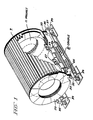
- the shield comprises a cylindrical shell fabricated with staves 13 of magnetic material such as low carbon steel or ingot iron affixed to disk shaped end caps of magnetic material 15. Alternatively, the shell can be fabricated from rolled sheets welded together.
- Each stave comprises a plurality of half inch plates of magnetic material. The plates are joined together such as by tack welding with the plates arranged to conform with the curvature of the end caps. The ends of the staves are machined to assure a good fit with the end cap face.
- Each of the end caps 15 are made up of two segmented disks, a smaller diameter disk 15a and a larger diameter disk 15b concentrically joined to one another using bolts 17.
- the smaller and larger disk shaped end caps each comprise segments of magnetic material such as ingot iron or low carbon steel.
- the joints of the larger and smaller diameter disks staggered relative to one another.
- the larger diameter disk forms a flange extending around the periphery of the smaller diameter disk.
- Circumferentially arranged bolt holes extend axially through the larger diameter disk and align with tapped holes in the stave ends.
- the staves rest on the periphery of the smaller diameter disks and are securely joined to the inside faces of the larger disks using bolts 19.
- the disk shaped end caps define a central aperture extending longitudinally through the end caps. The diameter of the aperture is at least as great as the bore of the magnet 11 and does not interfere with access to the working space inside the bore of the magnet.
- Spacing from the exterior of the MR magnet to the inner diameter is approximately 10 centimeters.
- the magnet 11 rests on two cradles 21 of nonmagnetic material such as austenetic stainless steel or aluminum.
- the two cradles are longitudinally spaced apart and situated under the cylindrical magnet.
- the cradle includes struts 23 which are welded between a base plate 25 and a saddle 27.
- the struts 23 extend between the staves 13 of the shield 9.
- Tewo longitudinally extending nonmagnetic channels 29 join the front and back base plates. The channels extend beyond the base plates of the cradles allowing vertical adjustment of the magnet relative to the shield.
- Two longitudinal channels 31 join the front and back strut portions on either side to allow for lateral adjustment of the magnet relative to the shield.
- each of the large diameter end caps 15b each have two horizontally extending support sections 33, each of which are secured to a block of nonmagnetic material 35 such as by bolting.
- the blocks of material in turn rests on two longitudinally extending I beams 37.
- Each I beam supporting one side of each of the large diameter end plates.
- the I beams are each supported on either end on base plates 39 to spread the load of the shield.
- the magnet is movable relative to the shield which is fixed.
- the magnet is adjusted so that the longitudinal axes of the magnet is coaxial with the magnetic axis of the MR magnet.
- the magnetic axis is defined as a line in space across which the flux density does not change.
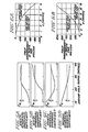
- the stray field for a 1.5 Tesla MR magnet adjusted with compensating coils to achieve a uniform field in the working volume is shown in Figure 3A.
- the MR magnet is a solenoidal type and the field is measured from the center of the working volume.
- the R direction extends radially from the center of the working volume of the magnet and the Z direction extends longitudinally from the magnet and also is measured from the center of the working space.
- a field strength of 1 gauss can cause interference with the operation of PET scanners, CT scanners and color televisions.
- a three gauss field can cause interference with the operation of metal detectors.
- a five gauss field can cause interference with the operation of cardiac pacemakers and neuro stimulators.
- a 10 gauss field can cause interference with the operation of x-ray tubes and the magnetic resonance scanners main computer and image processor.
- a 30 gauss field can cause interference with the remote console used with a magnetic resonance scanner.
- the earth's magnetic field is a 0.5 gauss.
- a stray field reduction is achieved by surrounding the magnet with a shell of ferromagnetic material.
- the ferromagnetic material attracts lines of flux which reduce the amount of flux passing through the air outside the shield.
- the MR magnet provides a uniform dc field with the north and south poles at opposite axial ends of the magnets. Lines of flux pass from the north . pole of the magnet radially through the end cap and then in the axial direction through the cylinder and radially through the opposite end cap to the south pole of the magnet. Other lines of flux pass directly into the shell and then in an axial direction and then back to the magnet.
- the gap between the stave ends and the flange is along the flux path, but since the stave ends are machined, leakage field is small.
- the leakage field can further be reduced using a filler material having suspended iron particles.
- the gaps between adjacent staves is not a problem since the flux does not flow circumferentially in the cylindrical shell.
- the shield magnetic material saturates in the presence of the magnetic field generated by the MR magnet.
- the graph of Figure 3B shows the field in the axial and radial direction with the shield in place and the compensating coils adjusted for a uniform field.
- the shield saturates during operation of the magnet.
- the presence of the cylindrical shell reduces the stray field but at the same time introduces perturbations in the working volume.
- the ratings of the adjusting coils of the retrofitted machine can easily provide compensating currents in the adjusting coils within their originally designed capability.
- FIG. 5A-D spherical harmonic coefficients at the origin of a shielded 0.8T MR magnet plotted as a function of the end cap openings.
- the shield around the MR magnet is 5 inches thick and does not saturate during magnet operation.
- the spherical harmonic coefficients when combined give the field inhomogeneity in the field.
- the odd harmonic coefficients cancel one another and the higher the even numbered coefficients generally the smaller contribution to the field inhomogeneity.
- the total weight of the shield 41 can be minimized by ensuring that each part of the shield participates equally in diverting flux away from the external environment. This is achieved by having a variable thickness cylindrical shell.
- the shell thickness is thicker in the central portion, since more flux is carried in the shield in that section with a reduction in shell thickness in the portions of the shell further away from the center.
- the shield can be fabricated using staves comprising half inch ingot iron plates or low carbon steel plates having the desired profile and secured in the same manner as the plates shown in Figure 1.
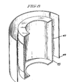
- FIG. 8 another embodiment of the present invention is shown.
- An inner cylindrical shell with end caps 45 is shown for situating around an MR magnet so that the longitudinal axis of the cylindrical shell and the magnetic axis of an MR magnet are coaxial.
- the inner shell is sized so that it can be in close proximity (approximately 10 cm, for example) all around the MR magnet.
- the inner cylindrical shell is of variable thickness, having a central portion 47 in the longitudinal direction thicker than the end portion of the shell.
- An outer cylindrical shell 49 without end caps surrounds the inner cylindrical shell and is coaxial therewith.
- the inner and outer shell can be fabricated of ferromagnetic material such as ingot iron or low carbon steel from rolled sheets welded together. Alternatively, the inner shell can be fabricated of variable thickness staves bolted to small and large diameter disks as shown in Figure 1.
- the outer shell can be formed of curved longitudinal sections of ingot iron or low carbon steel joined together by splice plates.
- the extent of the stray field 5 gauss line can be reduced from 6.2 meters to 1.5 meters, for example, with a double field having the following dimensions.
- the inner diameter is approximately 10 centimeters.
- the inner shell carries as much of the flux generated by the MR magnet consistent with a weight optimized design.
- the weight optimized design requires the inner shell to be saturated with each part of the shield participating equally in diverting flux away from the external environment by using a variable thickness shield with a thicker shield where the amount of flux passing through the shield at that location is greater.
- the outer shell is spaced apart from the inner shell at a distance sufficient to keep the flux passing through the inner shell to be diverted to the outer shell.
- the outer shell thickness is chosen so that it saturates during operation.
- the outer shell carrier additional flux, reducing the five gauss line surrounding the magnet.
- Perturbation to the working volume is reduced by situating the shield so that the longitudinal axis of the shield and the magnetic axis of the magnet are coaxial.
- the radial extent of the central aperture in each end cap is adjusted to copensate for the perturbation introduced by the cylindrical shields alone.
- the effect of including or removing the outer shield is seen to be only a two parts per million variation in a total peak-to-peak inhomogeneity of sixty five parts per million. This means that removal of the outer shield, where environmental conditions permit, has a negligible effect on the conditions inside the working volume.
- a single setting of the shim currents should be sufficient for the shield configuration of Figure 8 whether it is single or double. The double shield configuration therefore gives an MR magnet added siting flexibility.
- the foregoing describes a shield for an MR magnet which reduces the stray field using the least amount of ferromagnetic material while at the same time minimizing the effect of the shield on the field inhomogeneity in the working volume of the MR magnet.
Landscapes
- Engineering & Computer Science (AREA)
- Power Engineering (AREA)
- Physics & Mathematics (AREA)
- Health & Medical Sciences (AREA)
- Epidemiology (AREA)
- Condensed Matter Physics & Semiconductors (AREA)
- General Physics & Mathematics (AREA)
- Magnetic Resonance Imaging Apparatus (AREA)
- Shielding Devices Or Components To Electric Or Magnetic Fields (AREA)
Applications Claiming Priority (2)
| Application Number | Priority Date | Filing Date | Title |
|---|---|---|---|
| US06/715,435 US4646045A (en) | 1985-03-25 | 1985-03-25 | Aperture sized disc shaped end caps of a ferromagnetic shield for magnetic resonance magnets |
| US715435 | 1985-03-25 |
Publications (3)
| Publication Number | Publication Date |
|---|---|
| EP0196511A1 true EP0196511A1 (de) | 1986-10-08 |
| EP0196511B1 EP0196511B1 (de) | 1990-05-23 |
| EP0196511B2 EP0196511B2 (de) | 1994-04-06 |
Family
ID=24874040
Family Applications (1)
| Application Number | Title | Priority Date | Filing Date |
|---|---|---|---|
| EP86103343A Expired - Lifetime EP0196511B2 (de) | 1985-03-25 | 1986-03-12 | Ferromagnetische Abschirmung für magnetische Resonanzmagnete |
Country Status (6)
| Country | Link |
|---|---|
| US (1) | US4646045A (de) |
| EP (1) | EP0196511B2 (de) |
| JP (1) | JPH0793208B2 (de) |
| CA (1) | CA1271986A (de) |
| DE (1) | DE3671566D1 (de) |
| IL (1) | IL78063A (de) |
Cited By (7)
| Publication number | Priority date | Publication date | Assignee | Title |
|---|---|---|---|---|
| GB2214312A (en) * | 1988-01-22 | 1989-08-31 | Mitsubishi Electric Corp | Electromagnet with a magnetic shield |
| USD306717S (en) | 1987-03-27 | 1990-03-20 | Kabushiki Kaisha Toshiba | Shield for a superconducting magnet |
| GB2237881A (en) * | 1989-11-06 | 1991-05-15 | Elscint Ltd | Passive magnetic shield |
| US5367261A (en) * | 1992-07-02 | 1994-11-22 | General Electric Company | Shield for a magnetic resonance imaging coil |
| US6172587B1 (en) | 1996-09-19 | 2001-01-09 | Bruker Analytik Gmbh | Ferromagnetic spatial shielding for the superconducting high field magnet of an NMR spectrometer |
| EP2458599A1 (de) * | 2010-11-24 | 2012-05-30 | General Electric Company | Magnetische Abschirmung für Stromwandler in einem elektronischen Wattstundenzähler |
| US10976393B2 (en) | 2017-04-28 | 2021-04-13 | Aspect Imaging Ltd. | System for reduction of a magnetic fringe field of a magnetic resonance imaging device |
Families Citing this family (28)
| Publication number | Priority date | Publication date | Assignee | Title |
|---|---|---|---|---|
| DE3511750A1 (de) * | 1985-03-30 | 1986-10-09 | Philips Patentverwaltung Gmbh, 2000 Hamburg | Spulenanordnung fuer kernspinuntersuchungen |
| DE3650778T2 (de) * | 1985-09-20 | 2004-02-05 | Btg International Ltd. | Magnetfeldschirme |
| DE3769194D1 (de) * | 1986-04-21 | 1991-05-16 | Siemens Ag | Rahmenstruktur fuer ein magnetsystem einer anlage zur kernspin-tomographie. |
| US4701737A (en) * | 1986-05-30 | 1987-10-20 | The United States Of America As Represented By The Secretary Of The Army | Leakage-free, linearly varying axial permanent magnet field source |
| JP2603944B2 (ja) * | 1986-11-13 | 1997-04-23 | 株式会社東芝 | Mri装置用磁石の磁気遮蔽体 |
| US4698611A (en) * | 1986-12-03 | 1987-10-06 | General Electric Company | Passive shimming assembly for MR magnet |
| US4837541A (en) * | 1987-04-02 | 1989-06-06 | General Electric Company | Shield suspension system for a magnetic resonance cryostat |
| US4771256A (en) * | 1987-04-02 | 1988-09-13 | General Electric Company | Integral shield for mr magnet |
| JPS63281410A (ja) * | 1987-05-13 | 1988-11-17 | Mitsubishi Electric Corp | 磁気シ−ルド付電磁石 |
| JPS63307711A (ja) * | 1987-06-10 | 1988-12-15 | Toshiba Corp | 磁石装置 |
| US4783628A (en) * | 1987-08-14 | 1988-11-08 | Houston Area Research Center | Unitary superconducting electromagnet |
| US4822772A (en) * | 1987-08-14 | 1989-04-18 | Houston Area Research Center | Electromagnet and method of forming same |
| US4743880A (en) * | 1987-09-28 | 1988-05-10 | Ga Technologies Inc. | MRI magnet system having shield and method of manufacture |
| US4953555A (en) * | 1987-10-20 | 1990-09-04 | The United States Of Americas As Represented By The Secretary Of The Army | Permanent magnet structure for a nuclear magnetic resonance imager for medical diagnostics |
| US5016638A (en) * | 1989-03-01 | 1991-05-21 | Hsieh Chi H | Vibration control in NMR magnet structures |
| US4931759A (en) * | 1989-04-06 | 1990-06-05 | General Atomics | Magnetic resonance imaging magnet having minimally symmetric ferromagnetic shield |
| US5001447A (en) * | 1989-08-23 | 1991-03-19 | General Electric Company | Ferromagnetic compensation rings for high field strength magnets |
| US5220302A (en) * | 1990-01-22 | 1993-06-15 | The University Of Texas System Board Of Regents | Nmr clinical chemistry analyzer and method of forming a shield |
| US5128643A (en) * | 1990-09-24 | 1992-07-07 | Newman David E | Method and apparatus for producing a region of low magnetic field |
| US5382904A (en) * | 1992-04-15 | 1995-01-17 | Houston Advanced Research Center | Structured coil electromagnets for magnetic resonance imaging and method for fabricating the same |
| US5359310A (en) * | 1992-04-15 | 1994-10-25 | Houston Advanced Research Center | Ultrashort cylindrical shielded electromagnet for magnetic resonance imaging |
| US6181137B1 (en) * | 1999-07-26 | 2001-01-30 | General Electric Company | Unified shimming for magnetic resonance superconducting magnets |
| US6566991B1 (en) * | 2001-04-24 | 2003-05-20 | Fonar Corporation | Apparatus and method of shimming a magnetic field |
| US20080171931A1 (en) * | 2007-01-16 | 2008-07-17 | Michael Maschke | Device and procedure for cardiac treatment with a MRI - X-ray hybrid system |
| US10755190B2 (en) | 2015-12-21 | 2020-08-25 | D-Wave Systems Inc. | Method of fabricating an electrical filter for use with superconducting-based computing systems |
| WO2018029666A1 (en) * | 2016-08-08 | 2018-02-15 | Aspect Imaging Ltd. | Device, system and method for obtaining a magnetic measurement with permanent magnets |
| US11988730B2 (en) | 2016-08-08 | 2024-05-21 | Aspect Imaging Ltd. | Device, system and method for obtaining a magnetic measurement with permanent magnets |
| US12591029B2 (en) | 2022-03-07 | 2026-03-31 | D-Wave Systems Inc. | Thermally isolating cabling assemblies, systems using thermally isolating cabling assemblies, and methods of fabricating thermally isolating cabling assemblies |
Citations (5)
| Publication number | Priority date | Publication date | Assignee | Title |
|---|---|---|---|---|
| US4233583A (en) * | 1978-09-22 | 1980-11-11 | Bicron Electronics Company | Flux shielded solenoid |
| US4340770A (en) * | 1979-09-21 | 1982-07-20 | Allied Corporation | Enhancement of the magnetic permeability in glassy metal shielding |
| GB2123639A (en) * | 1982-07-09 | 1984-02-01 | Us Energy | Magnetic shield |
| US4460884A (en) * | 1981-07-04 | 1984-07-17 | U.S. Philips Corporation | Transformer comprising a magnetic screen |
| US4471333A (en) * | 1981-04-28 | 1984-09-11 | Sprecher & Schuh Ag | Current transformer with a ring-shaped core for use in a high voltage switching device enclosed in a metallic casing |
Family Cites Families (13)
| Publication number | Priority date | Publication date | Assignee | Title |
|---|---|---|---|---|
| US3008044A (en) * | 1960-02-25 | 1961-11-07 | Gen Electric | Application of superconductivity in guiding charged particles |
| JPS51477A (de) * | 1974-06-17 | 1976-01-06 | Isao Oo | |
| US3924210A (en) * | 1974-11-01 | 1975-12-02 | Raytheon Co | Field shaping magnet structure |
| US4390494A (en) * | 1980-04-07 | 1983-06-28 | Energy Profiles, Inc. | Directed beam fusion reaction with ion spin alignment |
| DE3123493A1 (de) * | 1981-06-13 | 1982-12-30 | Bruker Analytische Meßtechnik GmbH, 7512 Rheinstetten | Elektromagnet fuer die nmr-tomographie |
| US4388601A (en) * | 1981-09-30 | 1983-06-14 | Varian Associates, Inc. | Symmetrizing means for RF coils in a microwave cavity |
| DE3245945A1 (de) * | 1982-12-11 | 1984-06-14 | Bruker Analytische Meßtechnik GmbH, 7512 Rheinstetten | Elektromagnet fuer die nmr-tomographie |
| DE3245944A1 (de) * | 1982-12-11 | 1984-06-14 | Bruker Analytische Meßtechnik GmbH, 7512 Rheinstetten | Elektromagnet fuer die nmr-tomographie |
| US4585994A (en) * | 1983-07-15 | 1986-04-29 | Henry Ford Hospital | Nuclear magnetic resonance imaging system |
| FR2551302B1 (fr) * | 1983-08-30 | 1986-03-14 | Commissariat Energie Atomique | Structure ferromagnetique d'une source d'ions creee par des aimants permanents et des solenoides |
| DE3333755A1 (de) * | 1983-09-19 | 1985-04-18 | Siemens AG, 1000 Berlin und 8000 München | Magneteinrichtung einer anlage der kernspin-tomographie mit einer abschirmvorrichtung |
| NL8303535A (nl) * | 1983-10-14 | 1985-05-01 | Philips Nv | Kernspinresonantie apparaat. |
| GB8332177D0 (en) * | 1983-12-01 | 1984-01-11 | Oxford Magnet Tech | Magnet system |
-
1985
- 1985-03-25 US US06/715,435 patent/US4646045A/en not_active Expired - Lifetime
-
1986
- 1986-03-06 IL IL78063A patent/IL78063A/xx unknown
- 1986-03-12 EP EP86103343A patent/EP0196511B2/de not_active Expired - Lifetime
- 1986-03-12 DE DE8686103343T patent/DE3671566D1/de not_active Expired - Lifetime
- 1986-03-14 CA CA000504139A patent/CA1271986A/en not_active Expired - Lifetime
- 1986-03-24 JP JP61064276A patent/JPH0793208B2/ja not_active Expired - Lifetime
Patent Citations (5)
| Publication number | Priority date | Publication date | Assignee | Title |
|---|---|---|---|---|
| US4233583A (en) * | 1978-09-22 | 1980-11-11 | Bicron Electronics Company | Flux shielded solenoid |
| US4340770A (en) * | 1979-09-21 | 1982-07-20 | Allied Corporation | Enhancement of the magnetic permeability in glassy metal shielding |
| US4471333A (en) * | 1981-04-28 | 1984-09-11 | Sprecher & Schuh Ag | Current transformer with a ring-shaped core for use in a high voltage switching device enclosed in a metallic casing |
| US4460884A (en) * | 1981-07-04 | 1984-07-17 | U.S. Philips Corporation | Transformer comprising a magnetic screen |
| GB2123639A (en) * | 1982-07-09 | 1984-02-01 | Us Energy | Magnetic shield |
Cited By (10)
| Publication number | Priority date | Publication date | Assignee | Title |
|---|---|---|---|---|
| USD306717S (en) | 1987-03-27 | 1990-03-20 | Kabushiki Kaisha Toshiba | Shield for a superconducting magnet |
| GB2214312A (en) * | 1988-01-22 | 1989-08-31 | Mitsubishi Electric Corp | Electromagnet with a magnetic shield |
| GB2214312B (en) * | 1988-01-22 | 1992-03-11 | Mitsubishi Electric Corp | Electromagnet with a magnetic shield |
| GB2237881A (en) * | 1989-11-06 | 1991-05-15 | Elscint Ltd | Passive magnetic shield |
| GB2237881B (en) * | 1989-11-06 | 1994-08-31 | Elscint Ltd | Passive magnetic shield for magnetic resonance systems |
| US5367261A (en) * | 1992-07-02 | 1994-11-22 | General Electric Company | Shield for a magnetic resonance imaging coil |
| US6172587B1 (en) | 1996-09-19 | 2001-01-09 | Bruker Analytik Gmbh | Ferromagnetic spatial shielding for the superconducting high field magnet of an NMR spectrometer |
| EP2458599A1 (de) * | 2010-11-24 | 2012-05-30 | General Electric Company | Magnetische Abschirmung für Stromwandler in einem elektronischen Wattstundenzähler |
| US8664935B2 (en) | 2010-11-24 | 2014-03-04 | General Electric Company | Magnetic shield for current transformer in electronic watt-hour meter |
| US10976393B2 (en) | 2017-04-28 | 2021-04-13 | Aspect Imaging Ltd. | System for reduction of a magnetic fringe field of a magnetic resonance imaging device |
Also Published As
| Publication number | Publication date |
|---|---|
| US4646045A (en) | 1987-02-24 |
| IL78063A0 (en) | 1986-07-31 |
| JPS61252613A (ja) | 1986-11-10 |
| CA1271986A (en) | 1990-07-24 |
| EP0196511B1 (de) | 1990-05-23 |
| EP0196511B2 (de) | 1994-04-06 |
| IL78063A (en) | 1989-08-15 |
| DE3671566D1 (de) | 1990-06-28 |
| JPH0793208B2 (ja) | 1995-10-09 |
Similar Documents
| Publication | Publication Date | Title |
|---|---|---|
| EP0196511B1 (de) | Ferromagnetische Abschirmung für magnetische Resonanzmagnete | |
| US5999075A (en) | Open magnet with shielding | |
| EP0770881B1 (de) | Abgeschirmter und offener Magnet für die Bilderzeugung durch magnetische Resonanz | |
| EP0216404B1 (de) | Apparat zur Bilderzeugung mittels magnetischer Resonanz mit homogenisierenden magnetischen Elementen | |
| US5485088A (en) | Therapy tomograph with homogeneity device | |
| EP0782006B1 (de) | Aktiv geschirmte supraleitende Magnetanordnung für die bildgebende magnetische Resonanz | |
| US5237300A (en) | Support structure for actively shielded superconducting magnets | |
| US4743880A (en) | MRI magnet system having shield and method of manufacture | |
| US5396208A (en) | Magnet system for magnetic resonance imaging | |
| EP0414528B1 (de) | Ferromagnetische Kompensationsringe für Magnete hoher Feldstärke | |
| JPH0669027A (ja) | 磁場発生装置 | |
| US5874882A (en) | Open and shielded superconductive magnet | |
| US5084677A (en) | Magnetic field generating apparatus | |
| US4758812A (en) | Frame structure for a magnet system for nuclear spin tomography | |
| US5545997A (en) | Therapy tomograph with homogeneity device | |
| US6157279A (en) | Open magnet having shielding | |
| US7242191B2 (en) | Cold mass support structure and helium vessel of actively shielded high field open MRI magnets | |
| US6198371B1 (en) | Open magnet with floor mount | |
| US11688537B2 (en) | Electromagnet assembly | |
| US6218923B1 (en) | Magnet having shielding | |
| JPH0471324B2 (de) | ||
| US6215384B1 (en) | Magnet including shielding | |
| EP0139102B1 (de) | NMA-Abbildungssystem | |
| EP0940687A2 (de) | Offene Magneteinrichtung mit Abschirmung | |
| JP2617937B2 (ja) | 電磁石装置 |
Legal Events
| Date | Code | Title | Description |
|---|---|---|---|
| PUAI | Public reference made under article 153(3) epc to a published international application that has entered the european phase |
Free format text: ORIGINAL CODE: 0009012 |
|
| AK | Designated contracting states |
Kind code of ref document: A1 Designated state(s): CH DE FR GB IT LI NL SE |
|
| 17P | Request for examination filed |
Effective date: 19861024 |
|
| 17Q | First examination report despatched |
Effective date: 19880718 |
|
| GRAA | (expected) grant |
Free format text: ORIGINAL CODE: 0009210 |
|
| AK | Designated contracting states |
Kind code of ref document: B1 Designated state(s): CH DE FR GB IT LI NL SE |
|
| ET | Fr: translation filed | ||
| REF | Corresponds to: |
Ref document number: 3671566 Country of ref document: DE Date of ref document: 19900628 |
|
| ITF | It: translation for a ep patent filed | ||
| PLBI | Opposition filed |
Free format text: ORIGINAL CODE: 0009260 |
|
| 26 | Opposition filed |
Opponent name: SIEMENS AG GRPA3 ERL S Effective date: 19910222 |
|
| NLR1 | Nl: opposition has been filed with the epo |
Opponent name: SIEMENS AG. |
|
| REG | Reference to a national code |
Ref country code: GB Ref legal event code: 746 |
|
| ITPR | It: changes in ownership of a european patent |
Owner name: OFFERTA DI LICENZA AL PUBBLICO |
|
| REG | Reference to a national code |
Ref country code: FR Ref legal event code: DL |
|
| ITTA | It: last paid annual fee | ||
| PUAH | Patent maintained in amended form |
Free format text: ORIGINAL CODE: 0009272 |
|
| STAA | Information on the status of an ep patent application or granted ep patent |
Free format text: STATUS: PATENT MAINTAINED AS AMENDED |
|
| 27A | Patent maintained in amended form |
Effective date: 19940406 |
|
| AK | Designated contracting states |
Kind code of ref document: B2 Designated state(s): CH DE FR GB IT LI NL SE |
|
| REG | Reference to a national code |
Ref country code: CH Ref legal event code: AEN |
|
| NLR2 | Nl: decision of opposition | ||
| ET3 | Fr: translation filed ** decision concerning opposition | ||
| ITF | It: translation for a ep patent filed | ||
| NLR3 | Nl: receipt of modified translations in the netherlands language after an opposition procedure | ||
| EAL | Se: european patent in force in sweden |
Ref document number: 86103343.9 |
|
| PGFP | Annual fee paid to national office [announced via postgrant information from national office to epo] |
Ref country code: FR Payment date: 19950210 Year of fee payment: 10 Ref country code: CH Payment date: 19950210 Year of fee payment: 10 |
|
| PGFP | Annual fee paid to national office [announced via postgrant information from national office to epo] |
Ref country code: SE Payment date: 19950213 Year of fee payment: 10 |
|
| PGFP | Annual fee paid to national office [announced via postgrant information from national office to epo] |
Ref country code: GB Payment date: 19950228 Year of fee payment: 10 |
|
| PGFP | Annual fee paid to national office [announced via postgrant information from national office to epo] |
Ref country code: NL Payment date: 19950331 Year of fee payment: 10 |
|
| PGFP | Annual fee paid to national office [announced via postgrant information from national office to epo] |
Ref country code: DE Payment date: 19960223 Year of fee payment: 11 |
|
| PG25 | Lapsed in a contracting state [announced via postgrant information from national office to epo] |
Ref country code: GB Effective date: 19960312 |
|
| PG25 | Lapsed in a contracting state [announced via postgrant information from national office to epo] |
Ref country code: SE Effective date: 19960313 |
|
| PG25 | Lapsed in a contracting state [announced via postgrant information from national office to epo] |
Ref country code: LI Effective date: 19960331 Ref country code: CH Effective date: 19960331 |
|
| PG25 | Lapsed in a contracting state [announced via postgrant information from national office to epo] |
Ref country code: NL Effective date: 19961001 |
|
| GBPC | Gb: european patent ceased through non-payment of renewal fee |
Effective date: 19960312 |
|
| REG | Reference to a national code |
Ref country code: CH Ref legal event code: PL |
|
| PG25 | Lapsed in a contracting state [announced via postgrant information from national office to epo] |
Ref country code: FR Effective date: 19961129 |
|
| NLV4 | Nl: lapsed or anulled due to non-payment of the annual fee |
Effective date: 19961001 |
|
| EUG | Se: european patent has lapsed |
Ref document number: 86103343.9 |
|
| REG | Reference to a national code |
Ref country code: FR Ref legal event code: ST |
|
| REG | Reference to a national code |
Ref country code: CH Ref legal event code: AEN Free format text: MAINTIEN DU BREVET DONT L'ETENDUE A ETE MODIFIEE |
|
| PG25 | Lapsed in a contracting state [announced via postgrant information from national office to epo] |
Ref country code: DE Effective date: 19971202 |
|
| PG25 | Lapsed in a contracting state [announced via postgrant information from national office to epo] |
Ref country code: IT Free format text: LAPSE BECAUSE OF NON-PAYMENT OF DUE FEES;WARNING: LAPSES OF ITALIAN PATENTS WITH EFFECTIVE DATE BEFORE 2007 MAY HAVE OCCURRED AT ANY TIME BEFORE 2007. THE CORRECT EFFECTIVE DATE MAY BE DIFFERENT FROM THE ONE RECORDED. Effective date: 20050312 |
|
| PLAB | Opposition data, opponent's data or that of the opponent's representative modified |
Free format text: ORIGINAL CODE: 0009299OPPO |