EP0196521A2 - Dispositif d'application d'une matière de remplissage pour talons de pneus - Google Patents
Dispositif d'application d'une matière de remplissage pour talons de pneus Download PDFInfo
- Publication number
- EP0196521A2 EP0196521A2 EP86103453A EP86103453A EP0196521A2 EP 0196521 A2 EP0196521 A2 EP 0196521A2 EP 86103453 A EP86103453 A EP 86103453A EP 86103453 A EP86103453 A EP 86103453A EP 0196521 A2 EP0196521 A2 EP 0196521A2
- Authority
- EP
- European Patent Office
- Prior art keywords
- bead
- filler
- chuck
- filler material
- assembly
- Prior art date
- Legal status (The legal status is an assumption and is not a legal conclusion. Google has not performed a legal analysis and makes no representation as to the accuracy of the status listed.)
- Granted
Links
Images



Classifications
-
- B—PERFORMING OPERATIONS; TRANSPORTING
- B29—WORKING OF PLASTICS; WORKING OF SUBSTANCES IN A PLASTIC STATE IN GENERAL
- B29D—PRODUCING PARTICULAR ARTICLES FROM PLASTICS OR FROM SUBSTANCES IN A PLASTIC STATE
- B29D30/00—Producing pneumatic or solid tyres or parts thereof
- B29D30/06—Pneumatic tyres or parts thereof (e.g. produced by casting, moulding, compression moulding, injection moulding, centrifugal casting)
- B29D30/48—Bead-rings or bead-cores; Treatment thereof prior to building the tyre
- B29D30/50—Covering, e.g. by winding, the separate bead-rings or bead-cores with textile material, e.g. with flipper strips
-
- B—PERFORMING OPERATIONS; TRANSPORTING
- B29—WORKING OF PLASTICS; WORKING OF SUBSTANCES IN A PLASTIC STATE IN GENERAL
- B29D—PRODUCING PARTICULAR ARTICLES FROM PLASTICS OR FROM SUBSTANCES IN A PLASTIC STATE
- B29D30/00—Producing pneumatic or solid tyres or parts thereof
- B29D30/06—Pneumatic tyres or parts thereof (e.g. produced by casting, moulding, compression moulding, injection moulding, centrifugal casting)
- B29D30/48—Bead-rings or bead-cores; Treatment thereof prior to building the tyre
- B29D2030/482—Applying fillers or apexes to bead cores
-
- Y—GENERAL TAGGING OF NEW TECHNOLOGICAL DEVELOPMENTS; GENERAL TAGGING OF CROSS-SECTIONAL TECHNOLOGIES SPANNING OVER SEVERAL SECTIONS OF THE IPC; TECHNICAL SUBJECTS COVERED BY FORMER USPC CROSS-REFERENCE ART COLLECTIONS [XRACs] AND DIGESTS
- Y10—TECHNICAL SUBJECTS COVERED BY FORMER USPC
- Y10T—TECHNICAL SUBJECTS COVERED BY FORMER US CLASSIFICATION
- Y10T156/00—Adhesive bonding and miscellaneous chemical manufacture
- Y10T156/12—Surface bonding means and/or assembly means with cutting, punching, piercing, severing or tearing
- Y10T156/1317—Means feeding plural workpieces to be joined
- Y10T156/1343—Cutting indefinite length web after assembly with discrete article
-
- Y—GENERAL TAGGING OF NEW TECHNOLOGICAL DEVELOPMENTS; GENERAL TAGGING OF CROSS-SECTIONAL TECHNOLOGIES SPANNING OVER SEVERAL SECTIONS OF THE IPC; TECHNICAL SUBJECTS COVERED BY FORMER USPC CROSS-REFERENCE ART COLLECTIONS [XRACs] AND DIGESTS
- Y10—TECHNICAL SUBJECTS COVERED BY FORMER USPC
- Y10T—TECHNICAL SUBJECTS COVERED BY FORMER US CLASSIFICATION
- Y10T156/00—Adhesive bonding and miscellaneous chemical manufacture
- Y10T156/17—Surface bonding means and/or assemblymeans with work feeding or handling means
- Y10T156/1702—For plural parts or plural areas of single part
- Y10T156/1712—Indefinite or running length work
- Y10T156/1715—Means joining indefinite length work edge to edge
Definitions
- This invention relates to a means for fabricating a bead assembly utilized in the construction of a tire.
- the instant invention relates to a means and method for applying a filler to a bead whereby the filler is wrapped about the outer circumference of the bead and the ends of the filler are joined to completely encompass the bead.
- the instant invention employs an angled orientation of the end of the filler with respect to the radius of the bead in combination with offset application of the leading and trailing ends of the filler in order to facilitate the joining of the leading and trailing ends of the filler.
- Apparatus for applying a filler to a bead is well known in the art as disclosed by U.S. Patent No. 3,909,338 to Leblond et al. which discloses an apparatus and method for applying an elastomeric bead filler to a bead ring.
- the apparatus of Leblond has a pully for supporting a bead ring and a unit for advancing the filler strip to the outer periphery of the bead ring.
- Other units are provided for cutting the strip to a length corresponding to the circumference of the periphery of the bead ring, and for applying the strip to the periphery of the bead ring.
- U.S. Patent No. 4,226,663 and 4,298,421 to Pirovano et al. discloses a device for automatically loading a bead core to an apparatus which associates an elastomeric filler with the bead core and for unloading the bead core with the filler.
- the device employs two jaws for loading the bead core and means for controlling the opening of the jaws.
- a mechanism is employed for grasping each end of the filler in order to butt splice the ends of the filler about the bead.
- U.S. Patent No. 3,787,263 to Yonekawa et al. relates to a method and apparatus for automatically sticking an apex rubber strip on bead rings for use in pneumatic tires whereby a number of bead rings may be fed to and disposed on a pair of driving rollers, one by one, and a continuous apex rubber strip may be fed to the outer periphery of each ring.
- U.S. Patent No. 4,354,892 to Tarantola et al. discloses an apparatus provided with means suitable for stretching a filler when it is pulled into rotation with a bead core on the drum to stiffen the filler and resist bending, and therefore maintain the filler substantially in the drum midline.
- the apparatus of Tarantola et al. is further provided with means for discharging the bead core/filler assembly in a plane unchanged with respect to that determined by the stretching needs in order to permit the collection of various filler bead core assemblies one after another.
- a pair of fingers are utilized to splice the ends of the filler.
- U.S. Patent No. 4,410,389 in the name of Cole et al. discloses a continuously operating machine for forming filler bead core assemblies comprising a filler applicator where the bead core and an endless length of filler material in cylindrical form are disposed adjacent to one another, the filler material subsequently being rotated outwardly to lie on the outside of the bead core.
- the prior art devices are generally not adapted for the application of wide filler members to a bead without employing relatively complex application mechanism, especially for joining the ends of the bead filler.
- the instant invention solves this problem by-providing a relatively simple mechanism which is capable of applying wide bead filler members-to a bead wherein a tension gradiant is employed during the application of the filler member in combination with an offset application of the leading and trailing ends of the filler in order to provide application of the relatively wide filler to the bead wherein the application process is automatically performed by the relatively simple applicator mechanism.
- the present invention relates to a means and method for applying a filler to a bead and more particularly to an applicator mechanism adapted to apply a leading end of a continuous length of wide filler to a bead at an offset location and then causing the filler to wrap around the bead wherein the leading end of the filler is fixedly retained by a vacuum means in order to cause a tension gradiant within the filler whereby the trailing end of the filler may be severed and the trailing end of the filler applied to the bead at an offset location in order to provide an acceptable splice between the leading and trailing ends of the filler.
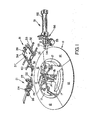
- Fig. 1 of the drawings there is shown a schematic representation of the instant invention.
- Bead chuck 11 is employed to retain a bead therein by clamping the inner diameter of the bead.
- the bead chuck 11 is comprised of four radially slidable chuck members 12 which are adapted to be displaced in a radial direction towards and away from the center of the bead chuck 11.
- the chuck members 12 are linked to center connector 13 by means of links 14.
- the center connector 13 is fixedly attached to the rod end of fluid cylinder 15 which may be selectively actuated to cause the center connector 13 to be vertically displaced with respect to the bead chuck 11. It may be readily seen that a vertical displacement of the center connector 13 utilizing fluid cylinder 15 will cause the radially slidable chuck members 12 to be displaced inwardly or outwardly in response to the displacement of the center connector 13.
- each of the chuck members 12 is a corresponding bead retaining lip 17 which is adapted to grasp the inner surface of a bead placed over the chuck members 12 when the chuck members 12 are displaced in a radially outward direction in response to a displacement of the fluid cylinder 15.
- the bead chuck 11 is adapted to be rotated about its longitudinal axis in order to facilitate the application of a filler to a bead as more fully disclosed below.
- a bead chuck 11 which is readily adapted to secure a bead thereto by causing the bead retaining lips of the chuck members 12 to engage the inner surface of the beads. The beads so secured can then be rotated in order to facilitate the application of a filler to the bead.
- the knife assembly 21 is employed to sever a portion of the filler from a continuous length provided to the knife assembly 21.
- the knife assembly 21 is comprised of a series of rollers 22 which are used to transport the filler material. Disposed above the rollers 22 are arm members 23 and 26.
- the arm members 23 and 26 are selectively actuated by means not shown in Fig. 1 to either a position allowing the filler to be transported along the rollers 22 or a position proximate the rollers 22 as shown in Fig. 1 wherein the arm members 23 and 26 retain the filler between the arm members 23 and 26 and the rollers 22 to facilitate the cutting of the filler material.
- a knife means 24 is employed to sever the filler material as it is being held by the arm members 23 and 26 and rollers 22.
- the knife means 24 is adapted to be linearly displaced by means more fully disclosed below across the path of the filler material to cause the filler material to thereby be severed.
- the knife means 24 has a cutting edge 25 which is angled with respect to the longitudinal axis of the filler material to thereby cause a beveled cut of the filler material for reasons which will be more fully discussed below.
- a knife assembly 21 which is adapted to cut the filler material such that the end of the filler material is beveled in order to co-act with the other end of the filler material in order to provide a smooth splice of the filler material when it is applied to the bead.
- the applicator assembly 31 is employed to transport the filler from the knife assembly 21 to the bead chuck 11.
- the applicator assembly 31 includes linear ways 32 which co-act with linear bearings 33 to provide a means for linearly displac ⁇ ing.platform 34.
- Disposed on the platform 34 are linear ways 36 which are adapted to co-act with linear bearings (not shown) .
- transport frame 37 Affixed to the transport frame 37 is manifold support 38 having disposed on the end thereof manifold 39.
- the manifold 39 is inoperative connection with a vacuum source via vacuum line 40.
- the manifold 39 may be positioned proximate to the rollers 22 of knife assembly 21 and a vacuum applied to the manifold in order to cause one end of the filler to be temporarily affixed to the manifold 39 due to the vacuum created within the manifold.
- the end of the filler can then be transported from the rollers 22 to the bead chuck 11 and applied to said bead chuck 11 in a manner more fully disclosed below.
- stitcher assembly 51 Disposed proximate to the applicator assembly 31 is stitcher assembly 51.
- the stitcher assembly 51 is comprised of a pneumatic cylinder 52 which has the barrel end thereof fixedly attached to the base of the bead applicator. Affixed to the rod end of the pneumatic cylinder 52 is stitcher mounting means 56 which is adapted to be positioned proximate to and away from said bead chuck 11 by means of the pneumatic cylinder 52.
- the stitcher mounting means 56 is comprised of an upper guide roll 53, a radial stitcher roll 54 and an angled stitcher roll 55.
- the stitcher mounting means 56 is employed to stitch the ends of the filler together after the filler has been applied to the bead chuck 11 in order to form an integral assembly with the bead and the filler and also to cause the filler to firmly adhere to the bead.
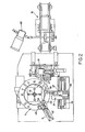
- Fig. 2 of the drawings there are disclosed further details of the instant invention.
- the feed conveyor assembly 61 is adapted to receive a continuous length of filler material from a continuous extruder, which extruder is well known in the art.
- the feed conveyor assembly 61 is adapted to transport the bead filler from the extruder to the knife assembly 21 where it is severed for subsequent application to the bead chuck 11.
- Both the extruder (not shown) and the feed conveyor assembly 61 are of a structure well known in the art.
- the filler is transported from the feed conveyor assembly 61 to the knife assembly 21.
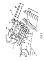
- the knife assembly is shown in more detail in Fig. 3 of the drawings.
- the knife assembly 21 includes arm member 23 actuated by pneumatic cylinder 41 which in turn actuates a rack mechanism which causes the arm member 23 to be rotated about its pivot.42 upon actuation of the pneumatic cylinder 41.
- the arm member 26 is also actuated by a pneumatic cylinder (not shown) which employs a linkage mechanism wherein the arm member 26 may be similarly rotated about a pivot point in order to allow the arm member 26 to be displaced toward the rollers 22.
- knife means 24 Disposed above the arm members 23 and 26 are knife means 24 having cutting edge 25 thereon.
- the knife means 24 is caused to move parallel to the axis of the rollers 22 by means of slide assembly 44 operatively connected to pneumatic cylinder 45.
- the pneumatic cylinder can thus selectively be actuated to cause the slide assembly 44 to be displaced in a direction parallel to the axis of the rollers 22 in order to cause the knife means 24 and its associated cutting edge 25 to traverse the length of the rollers 22 in order to sever a portion of filler material from the continuous length provided by the extruding means as more fully disclosed below.
- a transport means utilizing rollers 22 to allow the filler material to be transported with respect to the knife assembly 21 wherein the filler material may be severed by the knife assembly 21 upon actuation of the arm members 23 and 26 in a downward position against the filler member disposed on the rollers 22 supporting the bottom of the filler material wherein the filler material is securely retained by the arm members 23 and 26 in order to facilitate cutting of the filler member by knife means 24 which is caused to traverse the width of the filler member by actuation of the pneumatic cylinder 45 thereby causing slide assembly 44 to transport the knife means across the filler member to thereby sever a portion of the filler member from the continuous length provided by the extruding means.
- the cutting edge 25 of the knife means 24 is slightly angled with respect to the longitudinal axis of the filler material in order to provide a tapered edge of the end of the filler material which is employed as discussed below in more detail.
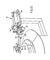
- the applicator assembly 31 is comprised of the manifold 39 in communication with a vacuum source via line.40 wherein the manifold 39 is adapted to pick up the end of the filler material and apply it to the bead chuck 11. It should be noted that the manifold 39 is mounted at an angled orientation corresponding to the angled orientation of the filler material and its relationship with the bead chuck 11.
- the manifold 39 is fixedly attached to the transport frame 37 which is adapted to be disposed relative to the platform 34 upon actuation of pneumatic cylinder 35 which causes the transport frame 37 to be displaced with respect to the platform 34.
- the transport frame 37 may be similarly displaced in an orthagonal direction by means of linear ways 32 co-acting with linear bearings 33.
- the transport frame 37 may be transported upon actuation of a pneumatic cylinder (not shown) in a direction orthagonal to the displacement of the manifold 39 provided by the pneumatic cylinder 35.
- the stitcher assembly 51 is comprised of a pneumatic cylinder 52 having affixed to the rod end thereof stitcher mounting means 56 which is adapted to have upper guide roll 53, radial stitching roll 54 and angled stitching roll 55 affixed thereto.
- the pneumatic cylinder 52 is energized to cause the stitcher mounting means 56 to be displaced towards the bead chuck 11 causing upper guide roll 53, radial stitcher roll 54 and angled stitcher roll 55 to engage the filler on the bead.
- the stitcher assembly 51 further causes the ends of the filler to be firmly stitched together.
- Figure 7 shows the bead chuck 11 in its retracted position ready for application of a bead thereto.
- the arm members of the knife assembly 21 are in their downward position retaining the filler material.
- Figure 8 of the drawings wherein the bead chuck 11 has been expanded to cause a bead 10 which was previously placed on the bead chuck 11 to be firmly retained thereby for application of the filler thereto.
- the applicator assembly 31 has been caused to be moved towards the knife assembly 21 in order to allow the applicator assembly 31 to pick up the end of the filler material at the knife assembly 21.
- the arm member 23 has been displaced away from the filler material in order to allow the applicator assembly to move the end of the filler material from the knife assembly to the bead chuck 11.
- the next sequence of the operation is the transport of the end of the filler material by the applicator assembly 31.
- the applicator assembly 31 causes the end of the filler material to be affixed to the bead chuck 11 at a position proximate to an orifice in the bead chuck 11, which orifice can be selectively in communication with a vacuum source to assist the transfer of the filler material from the manifold 39 to the bead chuck 11.
- the bead chuck 11 causes the filler material to be firmly biased against the bead retained by the bead chuck 11 in order to cause further adherence of the filler material to the bead chuck 11.
- the end of the filler material is applied at a position offset from the radial centerline of the bead chuck 11.
- the radial chuck centerline is defined as the line passing through the chuck center and which is perpendicular to the longitudinal axis of the unapplied filler.
- the applicator assembly As shown in Fig. 11 of the drawings is withdrawn and the stitcher assembly is caused to be actuated causing the upper, radial and angled stitcher rolls to engage the bead filler material causing the filler material to be biased against the bead retained on the bead chuck 11. Simultaneously, the bead chuck 11 is rotated to cause the filler member to be rotated about the bead chuck 11 and hence the bead retained by the bead chuck 11.
- the final sequence of operations shows the applicator assembly 31 applying the end of the filler material to the bead retained on the bead chuck 11.
- the bead chuck 1 1 is rotated in order to pass the splice past the stitche r assembly 51 to assure that the filler material has been stitched to the bead retained in the bead chuck 11.
- the instant invention is particularly adapted for the fully automated application of wide filler members to beads.
- the application of a wide filler member to a bead presents problems not associated with the application of narrow filler members to beads since there is an appreciable width of filler member that must be transported and applied to the bead member and the application of the wide filler member about the bead results in a considerable amount of distortion of the filler member due to the difference in the inner circumference of the filler member and the outer circumference of the filler member after it has been wrapped around a bead.
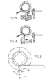
- the instant invention overcomes this problem by applying the leading edge of the rubber filler in a location that is offset 72 from the radial chuck centerline 71 as disclosed in Fig. 6 of the drawings.
- the trailing-edge of the rubber filler is also applied at a location 73 offset from the radial centerline of the bead chuck in the other direction.
- the leading and trailing edges of the filler material could be applied on the bead chuck centerline and produce a good splice.
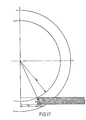
- the bead filler slowly slips with respect to the vacuum port and the leading edge of the filler material changes its angular orientation with respect to the bead retaining lip (See Fig. 16). Therefore the filler must be offset at the leading edge and optionally at the trailing edge to compensate for this slippage in order to produce an acceptable splice.
- the filler material is held in place at the point of application to the bead chuck 11 by the adhesion to the bead wire and at the bottom by the vacuum port 61.
- the outermost circumference is greater by a dimension a as compared to placing the leading edge on the chuck centerline 60.
- This dimension a is the key to making the edge match for the splices. This dimension can be mathematically shown as follows where:
- FIG. 16 shows the advantage length a afforded to the instant invention.
- This same principle can be applied to the trailing edge and would result in an advantage length in the opposite direction.
- This method of applying the trailing edge is used when required, depending on bead diameter, bead filler width, etc.
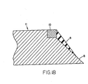
- Figure 18 is a cross sectional view of a portion of the bead chuck 11, a bead 10 mounted on said bead chuck, and the filler 9 affixed to the bead 10. It should be appreciated that the lateral axis at the filler 9 is at an angle with respect to the face of the bead 10 to which it is affixed as opposed to being perpendicular to the face of the bead as is conventional. The angle at which the filler 9 may be applied to the bead 10 may be varied by changing the angle of the chuck face 8.
- a means for applying a relatively wide bead filler material to a bead disposed on a bead chuck wherein the initial position of the leading edge of the bead filler material is offset from the centerline of the bead chuck in order to compensate for the stretching of the outer edge of the bead filler material that occurs during the application of the filler material about the bead in order to provide a proper splice of the leading end and trailing ends of the bead filler member after it has been applied to the bead.
- the trailing end Q ,f the bead filler material may similarly be offset in an opposite direction with respect to the leading edge of the bead filler material in order to produce and similar compensation for the stretching of the outer edge of the bead filler material in order to afford a proper splice between the leading and trailing edges of the bead filler material.
Landscapes
- Engineering & Computer Science (AREA)
- Mechanical Engineering (AREA)
- Tyre Moulding (AREA)
Applications Claiming Priority (2)
| Application Number | Priority Date | Filing Date | Title |
|---|---|---|---|
| US06/718,906 US4795522A (en) | 1985-04-02 | 1985-04-02 | Bead filler applicator |
| US718906 | 1985-04-02 |
Publications (3)
| Publication Number | Publication Date |
|---|---|
| EP0196521A2 true EP0196521A2 (fr) | 1986-10-08 |
| EP0196521A3 EP0196521A3 (en) | 1988-05-04 |
| EP0196521B1 EP0196521B1 (fr) | 1990-05-09 |
Family
ID=24888042
Family Applications (1)
| Application Number | Title | Priority Date | Filing Date |
|---|---|---|---|
| EP86103453A Expired - Lifetime EP0196521B1 (fr) | 1985-04-02 | 1986-03-14 | Dispositif d'application d'une matière de remplissage pour talons de pneus |
Country Status (5)
| Country | Link |
|---|---|
| US (1) | US4795522A (fr) |
| EP (1) | EP0196521B1 (fr) |
| JP (1) | JPS61229539A (fr) |
| CA (1) | CA1258612A (fr) |
| DE (1) | DE3670975D1 (fr) |
Cited By (5)
| Publication number | Priority date | Publication date | Assignee | Title |
|---|---|---|---|---|
| EP0312388A3 (en) * | 1987-10-16 | 1990-09-19 | Sumitomo Rubber Industries Limited | Method and apparatus for applying bead filler to a tyre |
| EP0345633A3 (fr) * | 1988-06-08 | 1991-09-11 | PIRELLI COORDINAMENTO PNEUMATICI S.p.A. | Dispositif pour appliquer un élément de remplissage en élastomère sur le talon d'un pneumatique |
| EP0466924A4 (en) * | 1990-02-15 | 1992-12-09 | Sumitomo Rubber Industries, Co. Ltd | Method of sticking bead apexes and apparatus therefor |
| EP0472958A3 (en) * | 1990-08-28 | 1993-03-03 | The Uniroyal Goodrich Tire Company | Method and apparatus for making an apexed bead ring |
| US5282912A (en) * | 1987-10-16 | 1994-02-01 | Sumitomo Rubber Industries, Ltd. | Method for applying bead flipper |
Families Citing this family (14)
| Publication number | Priority date | Publication date | Assignee | Title |
|---|---|---|---|---|
| US4968369A (en) * | 1988-10-03 | 1990-11-06 | Xerox Corporation | Belt fabrication machine |
| WO2001017761A1 (fr) * | 1999-09-03 | 2001-03-15 | Bartell Machinery Systems, Llc | Dispositif d'assemblage et de soudage de bourrages de tringle elastomeres sur des talons de pneu |
| KR20020039867A (ko) * | 2000-11-22 | 2002-05-30 | 조충환 | 비드필러 부착장치 |
| US20040089400A1 (en) * | 2002-11-08 | 2004-05-13 | Vargo Richard David | Method and apparatus for forming an annular elastomeric tire component |
| GB0412573D0 (en) * | 2004-06-04 | 2004-07-07 | A R T | Formation of a tire bead assembly |
| DE102005006076A1 (de) | 2005-02-10 | 2006-08-17 | Continental Aktiengesellschaft | Verfahren zum Aufwickeln und Spleißen eines Reifenaufbauteiles mit einer im Querschnittsprofil variierenden Materialdicke |
| KR100792549B1 (ko) | 2006-10-26 | 2008-01-09 | 금호타이어 주식회사 | 카카스 부착장치 |
| JP5675420B2 (ja) * | 2011-02-18 | 2015-02-25 | 株式会社ブリヂストン | タイヤの製造装置 |
| CN102229248B (zh) * | 2011-05-04 | 2013-06-05 | 天津赛象科技股份有限公司 | 三角胶热贴生产线 |
| US10456807B2 (en) * | 2014-11-25 | 2019-10-29 | Bartell Machinery Systems, L.L.C. | Bead-apex assembly systems |
| IT201600070310A1 (it) * | 2016-07-06 | 2018-01-06 | Bridgestone Europe Nv | Tamburo rotante a smontaggio rapido per la formazione di un tallone di un pneumatico |
| IT201600070333A1 (it) * | 2016-07-06 | 2018-01-06 | Bridgestone Europe Nv | Tamburo rotante con prelievo facilitato per la formazione di un tallone di un pneumatico |
| CN116533576A (zh) * | 2023-07-04 | 2023-08-04 | 青岛众屹科锐工程技术有限公司 | 一种双工位胎圈预置转台装置 |
| IT202400010333A1 (it) | 2024-05-08 | 2025-11-08 | Bridgestone Europe Nv Sa | Tamburo rotante regolabile per la formazione di un tallone di uno pneumatico |
Family Cites Families (9)
| Publication number | Priority date | Publication date | Assignee | Title |
|---|---|---|---|---|
| JPS4913507B1 (fr) * | 1970-12-19 | 1974-04-01 | ||
| FR2207021B1 (fr) * | 1972-11-22 | 1976-02-13 | Uniroyal Ste Fr | |
| IT1115688B (it) * | 1977-12-15 | 1986-02-03 | Pirelli | Dispositivo per l'applicazione di un riempitivo elastomerico ad un cerchietto di pneumatico |
| DE2803460A1 (de) * | 1978-01-27 | 1979-08-02 | Continental Gummi Werke Ag | Einrichtung zum belegen der wulstkerne von luftreifen mit profilstreifen aus vulkanisierbarem kautschuk |
| IT1094441B (it) * | 1978-04-19 | 1985-08-02 | Pirelli | Miglioramenti ad applicatrice di riempitivo elastomerico a cerchietto di pneumatico |
| IT1124588B (it) * | 1979-10-09 | 1986-05-07 | Pirelli | Perfezionamenti nelle apparecchiatura per l'applicazione di riempitivi elastomerici a cerchietti di pneumatici |
| DE3108142A1 (de) * | 1981-03-04 | 1982-09-16 | Continental Gummi-Werke Ag, 3000 Hannover | "vorrichtung zum auflegen von profilstreifen auf drahtkerne" |
| US4410389A (en) * | 1981-04-02 | 1983-10-18 | National-Standard Company | Bead and filler assembly machine |
| US4398988A (en) * | 1982-01-15 | 1983-08-16 | The B. F. Goodrich Company | Tire building apparatus |
-
1985
- 1985-04-02 US US06/718,906 patent/US4795522A/en not_active Expired - Fee Related
-
1986
- 1986-03-11 CA CA000503823A patent/CA1258612A/fr not_active Expired
- 1986-03-14 EP EP86103453A patent/EP0196521B1/fr not_active Expired - Lifetime
- 1986-03-14 DE DE8686103453T patent/DE3670975D1/de not_active Expired - Fee Related
- 1986-04-01 JP JP61072627A patent/JPS61229539A/ja active Pending
Cited By (5)
| Publication number | Priority date | Publication date | Assignee | Title |
|---|---|---|---|---|
| EP0312388A3 (en) * | 1987-10-16 | 1990-09-19 | Sumitomo Rubber Industries Limited | Method and apparatus for applying bead filler to a tyre |
| US5282912A (en) * | 1987-10-16 | 1994-02-01 | Sumitomo Rubber Industries, Ltd. | Method for applying bead flipper |
| EP0345633A3 (fr) * | 1988-06-08 | 1991-09-11 | PIRELLI COORDINAMENTO PNEUMATICI S.p.A. | Dispositif pour appliquer un élément de remplissage en élastomère sur le talon d'un pneumatique |
| EP0466924A4 (en) * | 1990-02-15 | 1992-12-09 | Sumitomo Rubber Industries, Co. Ltd | Method of sticking bead apexes and apparatus therefor |
| EP0472958A3 (en) * | 1990-08-28 | 1993-03-03 | The Uniroyal Goodrich Tire Company | Method and apparatus for making an apexed bead ring |
Also Published As
| Publication number | Publication date |
|---|---|
| EP0196521B1 (fr) | 1990-05-09 |
| US4795522A (en) | 1989-01-03 |
| CA1258612A (fr) | 1989-08-22 |
| DE3670975D1 (de) | 1990-06-13 |
| EP0196521A3 (en) | 1988-05-04 |
| JPS61229539A (ja) | 1986-10-13 |
Similar Documents
| Publication | Publication Date | Title |
|---|---|---|
| US4795522A (en) | Bead filler applicator | |
| US4608890A (en) | Method of cutting elastomeric material | |
| US5059274A (en) | Tire forming apparatus including upper and lower conveyors | |
| US4857123A (en) | Method for ply application | |
| JPH028893B2 (fr) | ||
| EP1447210B1 (fr) | Mise en forme et pose d'une nappe de ceinture de pneumatique sur un support | |
| KR20000052387A (ko) | 종이웨브의 접속부형성장치와 방법 | |
| US5486261A (en) | Method of and apparatus for automatically assembling bead apex | |
| US4824515A (en) | Ply applicator | |
| JPH03166149A (ja) | 帯状部材の供給方法および供給装置 | |
| US4588344A (en) | Roll transfer robot | |
| US4858505A (en) | Pivotable knife | |
| FR2546447A1 (fr) | Procede et machine de fabrication d'un composant annulaire de pneumatiques a partir d'une matiere en bande | |
| JP3494269B2 (ja) | 帯状材料の貼り付け方法及びその装置 | |
| EP0431922B1 (fr) | Enveloppement d'articles sous forme de rouleau | |
| US20260084914A1 (en) | Method and apparatus for automatically joining reels of web material | |
| CN218753956U (zh) | 贴胶装置及接带系统 | |
| US4061525A (en) | Tire bead covering apparatus | |
| JPH10156965A (ja) | 未加硫ゴムシートの貼付け方法及びその装置 | |
| JPH04135739A (ja) | 帯状部材の切断貼付け方法 | |
| EP0125146B1 (fr) | Dispositif de centrage à rouleaux | |
| JP2001030372A (ja) | ベルト材の繋ぎ目除去方法及びその装置 | |
| JP3423039B2 (ja) | シート材の貼り合わせ方法及び装置 | |
| US20050183815A1 (en) | Tire ply forming apparatus and process | |
| EP0286550A1 (fr) | Procédé de pose automatique d'éléments de protection pour les produits conditionnés en rouleau notamment et la machine pour la mise en oeuvre du procédé |
Legal Events
| Date | Code | Title | Description |
|---|---|---|---|
| PUAI | Public reference made under article 153(3) epc to a published international application that has entered the european phase |
Free format text: ORIGINAL CODE: 0009012 |
|
| AK | Designated contracting states |
Kind code of ref document: A2 Designated state(s): DE FR GB IT |
|
| PUAL | Search report despatched |
Free format text: ORIGINAL CODE: 0009013 |
|
| AK | Designated contracting states |
Kind code of ref document: A3 Designated state(s): DE FR GB IT |
|
| 17P | Request for examination filed |
Effective date: 19880420 |
|
| 17Q | First examination report despatched |
Effective date: 19880721 |
|
| GRAA | (expected) grant |
Free format text: ORIGINAL CODE: 0009210 |
|
| AK | Designated contracting states |
Kind code of ref document: B1 Designated state(s): DE FR GB IT |
|
| ET | Fr: translation filed | ||
| REF | Corresponds to: |
Ref document number: 3670975 Country of ref document: DE Date of ref document: 19900613 |
|
| ITF | It: translation for a ep patent filed | ||
| PLBE | No opposition filed within time limit |
Free format text: ORIGINAL CODE: 0009261 |
|
| STAA | Information on the status of an ep patent application or granted ep patent |
Free format text: STATUS: NO OPPOSITION FILED WITHIN TIME LIMIT |
|
| 26N | No opposition filed | ||
| PGFP | Annual fee paid to national office [announced via postgrant information from national office to epo] |
Ref country code: FR Payment date: 19911227 Year of fee payment: 7 |
|
| PGFP | Annual fee paid to national office [announced via postgrant information from national office to epo] |
Ref country code: GB Payment date: 19920213 Year of fee payment: 7 |
|
| PGFP | Annual fee paid to national office [announced via postgrant information from national office to epo] |
Ref country code: DE Payment date: 19920330 Year of fee payment: 7 |
|
| ITTA | It: last paid annual fee | ||
| PG25 | Lapsed in a contracting state [announced via postgrant information from national office to epo] |
Ref country code: GB Effective date: 19930314 |
|
| GBPC | Gb: european patent ceased through non-payment of renewal fee |
Effective date: 19930314 |
|
| PG25 | Lapsed in a contracting state [announced via postgrant information from national office to epo] |
Ref country code: FR Effective date: 19931130 |
|
| PG25 | Lapsed in a contracting state [announced via postgrant information from national office to epo] |
Ref country code: DE Effective date: 19931201 |
|
| REG | Reference to a national code |
Ref country code: FR Ref legal event code: ST |
|
| PG25 | Lapsed in a contracting state [announced via postgrant information from national office to epo] |
Ref country code: IT Free format text: LAPSE BECAUSE OF NON-PAYMENT OF DUE FEES;WARNING: LAPSES OF ITALIAN PATENTS WITH EFFECTIVE DATE BEFORE 2007 MAY HAVE OCCURRED AT ANY TIME BEFORE 2007. THE CORRECT EFFECTIVE DATE MAY BE DIFFERENT FROM THE ONE RECORDED. Effective date: 20050314 |