EP0196623A2 - Kassettenbehälter - Google Patents
Kassettenbehälter Download PDFInfo
- Publication number
- EP0196623A2 EP0196623A2 EP86104187A EP86104187A EP0196623A2 EP 0196623 A2 EP0196623 A2 EP 0196623A2 EP 86104187 A EP86104187 A EP 86104187A EP 86104187 A EP86104187 A EP 86104187A EP 0196623 A2 EP0196623 A2 EP 0196623A2
- Authority
- EP
- European Patent Office
- Prior art keywords
- side walls
- holder
- cassette
- base
- link
- Prior art date
- Legal status (The legal status is an assumption and is not a legal conclusion. Google has not performed a legal analysis and makes no representation as to the accuracy of the status listed.)
- Granted
Links
Images

Classifications
-
- G—PHYSICS
- G11—INFORMATION STORAGE
- G11B—INFORMATION STORAGE BASED ON RELATIVE MOVEMENT BETWEEN RECORD CARRIER AND TRANSDUCER
- G11B15/00—Driving, starting or stopping record carriers of filamentary or web form; Driving both such record carriers and heads; Guiding such record carriers or containers therefor; Control thereof; Control of operating function
- G11B15/675—Guiding containers, e.g. loading, ejecting cassettes
- G11B15/67563—Guiding containers, e.g. loading, ejecting cassettes with movement of the cassette perpendicular to its main side, i.e. top loading
- G11B15/67565—Guiding containers, e.g. loading, ejecting cassettes with movement of the cassette perpendicular to its main side, i.e. top loading of the cassette with holder
Definitions
- the present invention relates to a cassette holder and, more particularly, to a cassette holder for a cassette recording/playback apparatus such as, for example, a video cassette recording/playback apparatus.
- a tape cassette holder having a cassette stage into which a cassette is inserted, and a pair of side walls between which the cassette stage is movable in a direction perpendicular to a surface of the side walls.
- a disadvantage of this proposed cassette holder resides in the fact that holder includes a space which is unnecessary during a recording or reproducing operation but which is necessary for the cassette to be inserted into and removed from the cassette holder. Consequently, the proposed apparatus is not of a small size.
- the aim underlying the present invention essentially resides in providing a cassette holder of the aforementioned type which is compact and of a relatively small size.
- a cassette holder which includes a base means or chassis and a cassette stage selectively movable upwardly from the base means so as to form, with a lid or cover, a space into which the cassette may be inserted and removed.
- a supporting means rotatably supports the lid or cover in response to an angle of rotation thereof, with the space, formed by the cassette stage and the lid or cover, increasing upon an increase of the angle of rotation.
- Coupling means are connected to the base means, the cassette stage, and the supporting means, for moving the cassette stage upwardly and rotating the support means in such a manner that the angle of rotation of the supporting means increases in accordance with an increase of a distance between the base means and the cassette stage.
- the cassette holder includes a pair of X-shaped pivotal link mechanisms for holding the cassette stage, with each of the link mechanisms having one end thereof which is held by a chassis whereby the link mechanism support the cassette stage in such a manner that the cassette stage moves upward and downward relative to the chassis along a predetermined path.
- Lid supporting means are pivotally held against the right and left side walls of the cassette stage, with each of the lid supporting means being engaged with one of the X-shaped pivotal link mechanisms so that the lid supporting means are pivoted relative to the cassette stage in accordance with the upward and downward movements of the cassette stage.
- the holder means may, in accordance with the present invention, include a base plate and a pair of side walls, each extending downwardly from opposite ends of the base plate and including a slot in a lower portion thereof.
- the support means comprises a base plate connected to the lid or cover means and a pair of spaced sidewalls extending downwardly from opposite ends of the base plate of the support means.
- Each of the side walls of the base plate of the support means includes a hole or opening in a lower portion thereof and the side walls of the support means are pivoted to respective side walls of the holder means.
- the pair of X-shaped link mechanisms of the present invention may, for example, each include a first link member having a first end connected to the holder means and a second link member having a first end movably disposed in a longitudinal direction in a slot formed in respective side walls of the base means, or chassis with the respective slots being adapted to regulate a position of the first end of the second link member.
- the pair of side walls of the base means or chassis also include a reception portion pivotally connected to the second end of the respective first link members.
- the synchronizing shaft is mounted at the reception portions of the side walls of the base means or chassis.
- the cassette holder further includes a pair of L-shaped elastic pieces each of which have one end connected to the base plate of the support means, a corner portion which pivotally and coaxially connected to both walls of the holder means and the support means, and another end which includes a hole or opening which is shorter or less than the hole of the side wall of the base means in a longitudinal direction of the slot and which is compulsorily moved in the longitudinal direction by the first end of the first link member of the X-shaped link mechanisms.
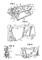
- a cassette holder according to the present invention includes a cassette stage generally designated by the reference numeral 2 having a base plate 22, spaced side walls 24, 26 provided at opposite ends of the base plate, and a lid or cover support generally designated by the reference numeral 4.
- the side walls 24, 26 along with a lid or cover 5 define a space for accommodating or storing a cassette l.
- the lid or cover 5 is mounted on a base plate 42 of the support 4.
- the support 4 includes spaced side walls 44, 46 which are respectively rotatably connected to the side walls 24, 26 by shafts 34, 36.
- a slot 266 is provided in each of the side walls 24, 26 of the cassette stage in a projection from the base plate 22.
- a hole or opening 468 is provided in each of the side walls 44, 46, with each hole or opening including at least one edge 468a extending over an arcuate or curved path.
- the cassette stage 2 is mounted so as to be movable between an upper open position and a lower closed position and vice versa, and the support 4 is rotatable in a clockwise and counterclockwise direction in accordance with a movement of the cassette stage 2. More particularly, an angle of rotation of the support 4 in the counterclockwise direction is the smallest when the cassette stage 2 is in the lowest position and largest when the cassette stage 2 is at the highest position.
- a pair of substantially L-shaped flexible arms 7 are provided and are respectively secured to shafts 34, 36, with each of the arms 7 being elastically deformable and coaxially pivotable together with the support 4.
- the pair of arms 7 are respectively mounted along the side walls 24, 26 of the support 4.
- One end 72 of each of the arms 7 is supported or fixed at a small opening or recess 462 of the support 4, with an opposite end 74 of each of the arms 7 being provided with a hole or opening 76.
- a shaft portion 8 is provided in each of the side walls 24, 26, with the shaft portions 8 being cooperable with respective guiding edges of the side walls 44, 46 defined between projections 464, 466 so as to enable a regulation of a rotation range of the support 4.
- a link mechanism generally designated by the reference numeral 9 is provided for regulating, controlling and driving the movements of the cassette stage 2 and rotation of the support 4.
- the link mechanism 9 is disposed on the right and left sides of the cassette stage 2 and, since the link mechanism 9 is of a symmetrical structure, description of the same will be limited with respect to one side thereof.
- the link mechanism 9 includes two link members 92, 9 4 pivotally connected to each other by a shaft 96 in order to link or connect the cassette stage 2 and the support 4 to a chassis generally designated by the reference numeral 6.
- the shaft 96 connects the link members 92, 94 to each other in such a manner that the link mechanism 9 has a substantially X-shaped configuration.
- One end of the link member 92 is connected to a slot 468 provided in the side wall 46 of the support 4 and a hole or opening 76 in the arm 7 by a shaft 101 which is movable in slot 266, hole or opening 468 and hole or opening 76.
- link member 92 is connected to a synchronizing shaft 103 which is held or mounted on the side wall 62 of the chassis 6, with the synchronizing shaft 103 being adapted to synchronize an operation of the pair of link members 92, 94 of the link mechanism 9.
- One end of the link member 94 is rotatably connected by a shaft 105 to a projection cut 242 provided at a front corner intersecting the base plate 22 and the side wall 26, while an opposite end of the link member 94 is connected to a slot 622 provided in the side wall 62 of the chassis 6 by a shaft 107 which is movable in the slot 62.
- All of the shafts, 96, 101, 103, 105 and 107 are locked or secured to the respective portions of the link members 92, 94 by suitable fastening means so as to prevent an inadvertent or accidental disconnection between the link members 92, 94 and the respective shafts during operation and, for example, the shaft 101 may be locked by a washer 110 and a lock means 110, such as, for example, a C-clip (Fig. 4).
- a torsion spring 120 is held or mounted at a projection 624 provided on the side wall 62 of the chassis 6.
- One end of the torsion spring 120 is in abutment with the projection 626 provided on the side wall 62 and the other end of the torsion spring 120 is engaged or abuts with a shaft 96 of the X-shaped link mechanism 9 so as to push or urge the shaft 96 in an upward direction.
- the cassette stage 2 When the cassette stage 2 is raised as shown in Fig. 2 and the cassette 1 is inserted therein, a sufficient gap A is secured or obtained between the cassette 1 and the lid or cover 5 so that the cassette 1 may be handled or manipulated in the gap A when inserted and removed.
- the cassette stage 2 follows a path determined by the X-shaped link mechanism 9 and drops to a closed position shown in Fig. 3 and is locked therein by a lock mechanism (not shown) provided at the front bottom of the cassette stage 2 and a front end of the chassis 6. In the closed position of Fig.
- the respective edges 52, 54 of the lid or cover 5 are disposed the nearest to edges 202, 204 of a cover member 200 and a dimension of the gap A between the cassette 1 and the lid or cover 5 is reduced to a gap B which is very small in comparison with the dimensions of the gap A (Fig. 2).
- the cassette stage 2 is lowered in the following series of movements. A downward pushing force applied to the lid or cover 5 acts on the cassette stage 2 through the shafts 34, 36 so as to lower the cassette stage 2 .
- the curved edge 468a of the hole or opening 468 in the side wall 46 lowers the shaft 101 so that the shaft 10-1 is moved downward and to the left and the shaft 107 is moved to the left in slot 622.
- torsion spring 120 is bent or deformed by a lowering of the shaft 96 to store energy for enabling a raising of the shaft 96.
- the cassette stage 2 When the cassette stage 2 is raised to the position shown in Fig. 2 from the position shown in Fig. 3 by releasing the lock mechanism at the front end, the cassette stage 2, support 4, and the associated components moved during a lowering of the cassette stage 2 are moved accordingly along a locus which is reversed to that taken during a lowering operation of the cassette stage by virtue of the spring force of the torsion spring 120.
Landscapes
- Packaging Of Annular Or Rod-Shaped Articles, Wearing Apparel, Cassettes, Or The Like (AREA)
- Automatic Tape Cassette Changers (AREA)
Applications Claiming Priority (2)
| Application Number | Priority Date | Filing Date | Title |
|---|---|---|---|
| JP60060648A JPH0831233B2 (ja) | 1985-03-27 | 1985-03-27 | カセツト保持装置 |
| JP60648/85 | 1985-03-27 |
Publications (3)
| Publication Number | Publication Date |
|---|---|
| EP0196623A2 true EP0196623A2 (de) | 1986-10-08 |
| EP0196623A3 EP0196623A3 (en) | 1988-08-17 |
| EP0196623B1 EP0196623B1 (de) | 1991-10-23 |
Family
ID=13148360
Family Applications (1)
| Application Number | Title | Priority Date | Filing Date |
|---|---|---|---|
| EP86104187A Expired EP0196623B1 (de) | 1985-03-27 | 1986-03-26 | Kassettenbehälter |
Country Status (4)
| Country | Link |
|---|---|
| US (1) | US4794478A (de) |
| EP (1) | EP0196623B1 (de) |
| JP (1) | JPH0831233B2 (de) |
| DE (1) | DE3682094D1 (de) |
Cited By (8)
| Publication number | Priority date | Publication date | Assignee | Title |
|---|---|---|---|---|
| FR2609830A1 (fr) * | 1987-01-21 | 1988-07-22 | Sony Corp | Mecanisme de chargement de cassette de bande magnetique |
| EP0302176A1 (de) * | 1987-08-07 | 1989-02-08 | Sharp Kabushiki Kaisha | Magnetisches Aufzeichnungs- und Wiedergabegerät |
| DE3842110A1 (de) * | 1987-12-15 | 1989-07-06 | Sony Corp | Aufzeichnungs- und/oder wiedergabegeraet fuer kassetten-aufzeichnungsmedien |
| GB2184590B (en) * | 1985-12-09 | 1990-06-06 | Gold Star Co | Improvement of the space for inserting or removing a tape cassette |
| EP0322056A3 (en) * | 1987-12-23 | 1990-11-22 | N.V. Philips' Gloeilampenfabrieken | Recording and/or reproducing apparatus for a tape-like record carrier |
| EP0509793A3 (de) * | 1991-04-16 | 1994-08-31 | Matsushita Electric Industrial Co Ltd | |
| CN1038002C (zh) * | 1992-06-20 | 1998-04-08 | 株式会社金星社 | 用于磁录放装置的磁带仓 |
| EP0918325A4 (de) * | 1997-03-12 | 1999-05-26 |
Families Citing this family (12)
| Publication number | Priority date | Publication date | Assignee | Title |
|---|---|---|---|---|
| JPS62120659A (ja) * | 1985-11-20 | 1987-06-01 | Matsushita Electric Ind Co Ltd | カセツト装着装置 |
| JPH0650842Y2 (ja) * | 1987-10-06 | 1994-12-21 | 松下電器産業株式会社 | テープカセット装填装置 |
| US5214548A (en) * | 1987-12-09 | 1993-05-25 | Mitsubishi Denki Kabushiki Kaisha | Tape cassette loading mechanism in tape player |
| JP2644888B2 (ja) * | 1989-04-24 | 1997-08-25 | 株式会社日立製作所 | カセット装着装置 |
| US5166918A (en) * | 1989-05-15 | 1992-11-24 | Seiko Epson Corporation | Loading mechanism for disk cartridges with vibration reducing mechanism |
| KR910008072Y1 (ko) * | 1989-05-23 | 1991-10-12 | 삼성전자 주식회사 | 디에이티용 카세트 하우징 |
| JPH0434755A (ja) * | 1990-05-30 | 1992-02-05 | Sony Corp | 磁気記録再生装置 |
| KR940000860Y1 (ko) * | 1991-06-24 | 1994-02-18 | 섬성전자 주식회사 | 테이프 레코더의 하우징 샤프트 회전을 이용한 테이프 안착장치 |
| JP3244896B2 (ja) * | 1992-12-17 | 2002-01-07 | 三星電子株式会社 | テープレコーダーのハウジング装置 |
| JPH08263902A (ja) * | 1995-03-22 | 1996-10-11 | Canon Inc | カセット装着装置及びこのカセット装着装置を備えた記録又は再生装置 |
| KR0127347Y1 (ko) * | 1995-06-28 | 1998-12-15 | 구자홍 | 탑로딩방식 캠코더의 카세트덮개 열림장치 |
| US6198596B1 (en) * | 1997-08-22 | 2001-03-06 | Canon Kabushiki Kaisha | Cassette mounting device having lock lever spring disposed in cassette holder |
Family Cites Families (10)
| Publication number | Priority date | Publication date | Assignee | Title |
|---|---|---|---|---|
| DE1233160B (de) * | 1966-03-22 | 1967-01-26 | Grundig Emv | Kassetten-Magnetbandgeraet |
| US3832734A (en) * | 1972-07-03 | 1974-08-27 | Ibm | Cassette loading and unloading apparatus |
| FR2221783B1 (de) * | 1973-03-16 | 1977-09-16 | Staar Sa | |
| JPS5535655Y2 (de) * | 1975-04-22 | 1980-08-22 | ||
| AU501919B2 (en) * | 1975-07-10 | 1979-07-05 | Sony Corporation | Circuits. comb |
| JPS5558842A (en) * | 1978-10-24 | 1980-05-01 | Victor Co Of Japan Ltd | Cassette mounting and demounting unit for tape recorder |
| JPS5686661U (de) * | 1979-12-07 | 1981-07-11 | ||
| JPS57113449A (en) * | 1980-12-29 | 1982-07-14 | Sony Corp | Tape driver |
| JPS57135467A (en) * | 1981-02-14 | 1982-08-21 | Sony Corp | Cassette loading device |
| JPS5933659A (ja) * | 1982-08-16 | 1984-02-23 | Sony Corp | カセツトエジエクト装置 |
-
1985
- 1985-03-27 JP JP60060648A patent/JPH0831233B2/ja not_active Expired - Lifetime
-
1986
- 1986-03-26 DE DE8686104187T patent/DE3682094D1/de not_active Expired - Lifetime
- 1986-03-26 EP EP86104187A patent/EP0196623B1/de not_active Expired
- 1986-03-27 US US06/844,507 patent/US4794478A/en not_active Expired - Lifetime
Cited By (18)
| Publication number | Priority date | Publication date | Assignee | Title |
|---|---|---|---|---|
| GB2184590B (en) * | 1985-12-09 | 1990-06-06 | Gold Star Co | Improvement of the space for inserting or removing a tape cassette |
| FR2609830A1 (fr) * | 1987-01-21 | 1988-07-22 | Sony Corp | Mecanisme de chargement de cassette de bande magnetique |
| US4866550A (en) * | 1987-08-07 | 1989-09-12 | Sharp Kabushiki Kaisha | Magnetic recording and reproducing apparatus with selective loading of different sized magnetic tapes |
| EP0302176A1 (de) * | 1987-08-07 | 1989-02-08 | Sharp Kabushiki Kaisha | Magnetisches Aufzeichnungs- und Wiedergabegerät |
| AU614559B2 (en) * | 1987-12-15 | 1991-09-05 | Sony Corporation | Cassette recording-medium recording and/or reproducing apparatus |
| GB2211980A (en) * | 1987-12-15 | 1989-07-12 | Sony Corp | Casette recording-medium recording and/or reproducing apparatus |
| US4954916A (en) * | 1987-12-15 | 1990-09-04 | Sony Corporation | Cassette loading apparatus with improved access |
| DE3842110A1 (de) * | 1987-12-15 | 1989-07-06 | Sony Corp | Aufzeichnungs- und/oder wiedergabegeraet fuer kassetten-aufzeichnungsmedien |
| GB2211980B (en) * | 1987-12-15 | 1992-03-18 | Sony Corp | Cassette recording-medium recording and/or reproducing apparatus. |
| EP0322056A3 (en) * | 1987-12-23 | 1990-11-22 | N.V. Philips' Gloeilampenfabrieken | Recording and/or reproducing apparatus for a tape-like record carrier |
| US5408370A (en) * | 1991-04-16 | 1995-04-18 | Matsushita Electric Industrial Co., Ltd. | Compact cassette loading device with movable tape guide member |
| EP0509793A3 (de) * | 1991-04-16 | 1994-08-31 | Matsushita Electric Industrial Co Ltd | |
| US5687040A (en) * | 1991-04-16 | 1997-11-11 | Matsushita Electric Industrial Co., Ltd. | Compact cassette loading device with movable tape guide member |
| EP0790610A3 (de) * | 1991-04-16 | 1998-07-22 | Matsushita Electric Industrial Co., Ltd. | Kassettenladevorrichtung |
| EP0790609A3 (de) * | 1991-04-16 | 1998-07-22 | Matsushita Electric Industrial Co., Ltd. | Kassettenladevorrichtung |
| CN1038002C (zh) * | 1992-06-20 | 1998-04-08 | 株式会社金星社 | 用于磁录放装置的磁带仓 |
| EP0918325A4 (de) * | 1997-03-12 | 1999-05-26 | ||
| US6115209A (en) * | 1997-03-12 | 2000-09-05 | Matsushita Electric Industrial Co., Ltd. | Cassette loading device |
Also Published As
| Publication number | Publication date |
|---|---|
| EP0196623B1 (de) | 1991-10-23 |
| JPS61220166A (ja) | 1986-09-30 |
| US4794478A (en) | 1988-12-27 |
| EP0196623A3 (en) | 1988-08-17 |
| JPH0831233B2 (ja) | 1996-03-27 |
| DE3682094D1 (de) | 1991-11-28 |
Similar Documents
| Publication | Publication Date | Title |
|---|---|---|
| EP0196623A2 (de) | Kassettenbehälter | |
| US4660784A (en) | Tap cartridge | |
| GB2093258A (en) | Cassette loading apparatus | |
| EP0367454B1 (de) | Kassettenbehälter für Bandrekorder | |
| US6705688B2 (en) | Electronic equipment | |
| US5517478A (en) | Disc player for performing disc loading and ejecting in response to opening and closing of lid | |
| KR100306182B1 (ko) | 테이프카세트 | |
| US5103357A (en) | Tape recorder including a device for opening a lid of tape cassette during the loading thereof | |
| US4954916A (en) | Cassette loading apparatus with improved access | |
| US6337840B1 (en) | Recording and/or playback apparatus of a recording medium | |
| US4561610A (en) | Tape cartridge loading apparatus | |
| EP0238752B1 (de) | Behälter für Datenspeicherelemente in Kombination mit einem Aufzeichnungs-/Wiedergabegerät zur Aufnahme des Behälters | |
| US4643304A (en) | Tape cartridge with extending reference surfaces | |
| US5602695A (en) | Cassette loading mechanism for recording and playback apparatus | |
| US4265442A (en) | Cassette locking and alignment assembly | |
| US5526210A (en) | Tape cassette for loading by a cassette inserting and ejecting apparatus | |
| US5920442A (en) | Cassette loading device | |
| EP1411511B1 (de) | Bandlaufwerkmechanismus | |
| US4623995A (en) | Recording disc reproducing device | |
| US5757577A (en) | Magnetic recording-playback apparatus for cassettes of two different sizes | |
| US5390056A (en) | Recording/reproducing apparatus capable of accepting tape cartridges of different sizes | |
| GB2250127A (en) | Lid opening mechanism for tape cassette | |
| JP3143376B2 (ja) | カセットホルダ機構 | |
| JP3322645B2 (ja) | カセットローディング機構 | |
| JPH04167262A (ja) | 磁気記録再生装置 |
Legal Events
| Date | Code | Title | Description |
|---|---|---|---|
| PUAI | Public reference made under article 153(3) epc to a published international application that has entered the european phase |
Free format text: ORIGINAL CODE: 0009012 |
|
| 17P | Request for examination filed |
Effective date: 19860326 |
|
| AK | Designated contracting states |
Kind code of ref document: A2 Designated state(s): DE FR GB IT |
|
| PUAL | Search report despatched |
Free format text: ORIGINAL CODE: 0009013 |
|
| AK | Designated contracting states |
Kind code of ref document: A3 Designated state(s): DE FR GB IT |
|
| 17Q | First examination report despatched |
Effective date: 19900410 |
|
| GRAA | (expected) grant |
Free format text: ORIGINAL CODE: 0009210 |
|
| AK | Designated contracting states |
Kind code of ref document: B1 Designated state(s): DE FR GB |
|
| REF | Corresponds to: |
Ref document number: 3682094 Country of ref document: DE Date of ref document: 19911128 |
|
| ET | Fr: translation filed | ||
| PLBE | No opposition filed within time limit |
Free format text: ORIGINAL CODE: 0009261 |
|
| STAA | Information on the status of an ep patent application or granted ep patent |
Free format text: STATUS: NO OPPOSITION FILED WITHIN TIME LIMIT |
|
| 26N | No opposition filed | ||
| REG | Reference to a national code |
Ref country code: GB Ref legal event code: IF02 |
|
| PGFP | Annual fee paid to national office [announced via postgrant information from national office to epo] |
Ref country code: GB Payment date: 20020315 Year of fee payment: 17 |
|
| PGFP | Annual fee paid to national office [announced via postgrant information from national office to epo] |
Ref country code: FR Payment date: 20020319 Year of fee payment: 17 |
|
| PGFP | Annual fee paid to national office [announced via postgrant information from national office to epo] |
Ref country code: DE Payment date: 20020426 Year of fee payment: 17 |
|
| PG25 | Lapsed in a contracting state [announced via postgrant information from national office to epo] |
Ref country code: GB Free format text: LAPSE BECAUSE OF NON-PAYMENT OF DUE FEES Effective date: 20030326 |
|
| PG25 | Lapsed in a contracting state [announced via postgrant information from national office to epo] |
Ref country code: DE Free format text: LAPSE BECAUSE OF NON-PAYMENT OF DUE FEES Effective date: 20031001 |
|
| GBPC | Gb: european patent ceased through non-payment of renewal fee |
Effective date: 20030326 |
|
| PG25 | Lapsed in a contracting state [announced via postgrant information from national office to epo] |
Ref country code: FR Free format text: LAPSE BECAUSE OF NON-PAYMENT OF DUE FEES Effective date: 20031127 |
|
| REG | Reference to a national code |
Ref country code: FR Ref legal event code: ST |