EP0196827A2 - Farbbildkathodenstrahlröhre - Google Patents
Farbbildkathodenstrahlröhre Download PDFInfo
- Publication number
- EP0196827A2 EP0196827A2 EP86302029A EP86302029A EP0196827A2 EP 0196827 A2 EP0196827 A2 EP 0196827A2 EP 86302029 A EP86302029 A EP 86302029A EP 86302029 A EP86302029 A EP 86302029A EP 0196827 A2 EP0196827 A2 EP 0196827A2
- Authority
- EP
- European Patent Office
- Prior art keywords
- cathode ray
- ray tube
- colour cathode
- shadow mask
- blackened
- Prior art date
- Legal status (The legal status is an assumption and is not a legal conclusion. Google has not performed a legal analysis and makes no representation as to the accuracy of the status listed.)
- Granted
Links
Images


Classifications
-
- H—ELECTRICITY
- H01—ELECTRIC ELEMENTS
- H01J—ELECTRIC DISCHARGE TUBES OR DISCHARGE LAMPS
- H01J29/00—Details of cathode-ray tubes or of electron-beam tubes of the types covered by group H01J31/00
- H01J29/02—Electrodes; Screens; Mounting, supporting, spacing or insulating thereof
- H01J29/06—Screens for shielding; Masks interposed in the electron stream
- H01J29/07—Shadow masks for colour television tubes
-
- H—ELECTRICITY
- H01—ELECTRIC ELEMENTS
- H01J—ELECTRIC DISCHARGE TUBES OR DISCHARGE LAMPS
- H01J29/00—Details of cathode-ray tubes or of electron-beam tubes of the types covered by group H01J31/00
- H01J29/02—Electrodes; Screens; Mounting, supporting, spacing or insulating thereof
- H01J29/06—Screens for shielding; Masks interposed in the electron stream
-
- H—ELECTRICITY
- H01—ELECTRIC ELEMENTS
- H01J—ELECTRIC DISCHARGE TUBES OR DISCHARGE LAMPS
- H01J2229/00—Details of cathode ray tubes or electron beam tubes
- H01J2229/07—Shadow masks
- H01J2229/0727—Aperture plate
- H01J2229/0777—Coatings
- H01J2229/0783—Coatings improving thermal radiation properties
Definitions
- This invention relates to a colour cathode ray tube, and more particularly to a blackened surface construction of its metallic members whose main constitutent is iron, such as the shadow mask assembly or the inner shield.
- a colour cathode ray tube has an envelope provided with a panel having a phosphor screen essentially consisting of a mosaic of phosphors emitting red, green, and blue light, a neck housing an electron gun, and a funnel that connects the panel and the neck.
- the electron beams emitted from the electron gun are selectively allowed to pass through to the screen by arranging, facing the phosphor screen, a shadow mask provided with a large number of apertures.
- the inner shield is fixed on the funnel side of the shadow mask.
- the material of the inner shield is required to have high permeability, to be electrically conductive, to have good forming properties, high mechanical strength and not to develop rust during the manufacturing process.
- Soft steel sheet is mainly iron and is therefore usually used for this purpose.
- the surfaces of the shadow mask assembly and/or inner shield are subjected to oxidative treatment to form a blackened film.
- This blackened film also serves to prevent rust.
- this blackened film itself gives rise to some problems such as poor withstand voltage characteristics and/or blockage of the apertures of the shadow mask caused by peeling of this blackened film, areas of lowered contrast due to insufficient suppression of scattered electrons, or reduced emission life due to production of gaseous impurities when the mask is struck by the electron beams.
- Japanese Patent Application Laid Open No.50-15766 discloses an attempt to obtain a black Fe-Al alloy surface by attaching aluminium to the surface of an iron inner shield and dispersing the aluminium in the surface of the inner shield by subjecting it to heat treatment. With this set-up, there is some improvement in respect of the problem of film peeling, but there is no improvement in respect of emission life, which ia reduced by gaseous impurities generated by the impingement of the electron beams.
- One object of this invention is to provide a colour cathode ray tube wherein loss of contrast due to scattered electrons is suppressed and emission life is increased.
- a colour cathode ray tube has a panel formed with a phosphor screen on its inside face; a neck has an electron gun assembly facing the phosphor screen; a funnel joins the neck to the pannel to constitute an envelope; a shadow mask assembly comprises a shadow mask arranged close to and facing the electron gun side of said phosphor screen and a mask frame supporting the shadow mask; and an inner shield extends on the electron gun side from this shadow mask assembly along the inner face of the funnel.
- Iron is the main constituent of said shadow mask assembly and the inner shield and at least one surface thereof is provided with a blackened region containing Al, Fe and Si, and the Si content in the surface vicinity of the blackened region is greater than 1.5 wt% and less than 30 wt%.
- the Si content is less than 1.5 wt%, there is no improvement in residual emission; if it is more than 30 wt%, peeling of the blackened region tends to occur. More preferably the Si content is selected from 4.0 wt% to 15 wt%.
- Fig. 1 and Fig. 2 show the construction of a colour cathode ray tube according to this invention.
- the colour cathode ray tube comprises an envelope formed by a panel 3 provided with a phosphor screen 4 formed with separate groups of phosphors that emit red, green and blue light respectively, and neck 1 facing phosphor screen 4, to which it is joined by a funnel 2.
- Neck 1 houses an electron gun assembly 7 that emits three electron beams.
- a shadow mask assembly 10 consisting firstly of a shadow mask 5 facing to phosphor screen 4 and having a large number of electron beam apertures 5a, and secondly of a mask frame 8 that supports this shadow mask 5 at its edges.
- An inner shield 6 extends along the inside face of funnel 2 from this shadow mask assembly 10 towards electron gun 7. Inner shield 6 is provided to prevent bending of the electron beams by the earth's magnetism.
- the three electron beams 9 emitted, accelerated and focussed from electron gun assembly 7 are scanned by means of a deflection yoke 12 arranged outside the funnel.
- the electron beams are condensed in the vicinity of the apertures 5a of shadow mask 5 and then diverge from these apertures.
- the colour picture is produced by the emission of light which occurs when the electron beams selectively land on the red, green and blue phosphors of phosphor screen 4.
- Blackened regions 11 are formed on the surface of the metal members, such as shadow mask assembly 10 and inner shield 6, which are in the tube and whose main constituent is Fe. Blackened regions 11 according to this embodiment of the invention enhance radiation of heat and suppress production of secondary electrons and have a rust-preventive effect. In addition, they give an improved emission life.
- the surface of the soft steel sheet which provides the substrate is cleaned with acid and cold rolled, then plated with molten aluminium.
- the aluminium material that is used for this plating with molten aluminium contains at least 0.5 to 15 wt% of Si.
- the plating thickness produced is about 10 micron to 20 micron.
- Next cold rolling is again performed to obtain the prescribed sheet thickness and the sheet is softened by annealing.
- the sheet is then formed to required shape in a cutting press and the blackened region is formed by heat treatment in a reducing atmosphere, for example a hydrogen atmosphere, or in vacuum.
- a reducing atmosphere for example a hydrogen atmosphere, or in vacuum.
- a blackened region formed by heat treatment in reducing atmosphere as described above was found to have the following characteristics.
- Fig. 4 shows the profile of the metallic constituents in the vicinity of the blackened region. Depth from the surface of the blackened region is shown along the horizontal axis and the metal content is shown along the vertical axis. As can be seen from this Figure, the maximum Si content is found at the surface.
- This blackened region is in the form of a layer but its boundary with the substrate is not well-defined. However, it has considerable adhesion to the substrate, and in a test in which a metal member treated as above was experimentally fitted in a cathode ray tube it was found to be effective in increasing the black body radiation of the metal member, thereby suppressing generation of reflected electrons. This reduction in the number of reflected electrons was apparent from the reduction in dark space luminance achieved by installation of the treated metal member.
- Fig. 3 shows the relationship between Si content and residual emissivity after a 3000 hour emission life test. From Fig. 3 it is clear that, above a Si content of about 1.5 wt%, the residual emissivity is better than in the case where the blackened region contains no Si.
- Fig. 3 shows the variation of residual emissivity with Si content (wt%) at the surface of the blackened region. It results in a necessary condition in which a Si content is more than 1.5 wt%. To be a marked improvement in residual emissivity a Si content of at least 4 wt% is desirable. On the other hand, it is not desirable for the Si content to exceed 30 wt%, since above this limit separation of the blackened layer in a cellophane adhesive tape adhesion test tends to occur.
- a cellophane adhesive tape adhesion test is carried out by sticking cellophane adhesive tape onto the blackened layer, and observing whether the blackened layer comes away when the tape is peeled off.) The results of the tape adhesion test are shown in the Table 1 below.
- the Al and Fe contents of the blackened region are preferably 35 to 65 wt% and 25 to 55 wt%, respectively.
- An inner shield for a 20-in cathode ray tube was formed using soft steel sheet of thickness 0.3 mm plated with molten Al on both faces. Vacuum heat treatment was then performed at 700 a C at a degree of vacuum of 10 -4 Torr, to form a blackened region consisting of at least Al, Fe and Si on the surface of the inner shield.
- the Si content in the Al on Al plating was about 7 to 8 wt%.
- This inner shield was mounted in a 20-in colour cathode ray tube.
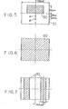
- the pattern 50 shown in Fig. 5 was displayed and the brightness of the dark region 51 was measured, to determine the degree of contrast produced by the tube.
- Table 3 gives the results of determination of dark region 51 luminance at points A and B in Fig. 5, taking the dark region luminance at these points in a conventionally manufactured tube as 100.
- this invention gives a colour cathode ray tube with dark region luminance, contrast, colour purity and emission life improved.
Landscapes
- Electrodes For Cathode-Ray Tubes (AREA)
- Vessels, Lead-In Wires, Accessory Apparatuses For Cathode-Ray Tubes (AREA)
Applications Claiming Priority (2)
| Application Number | Priority Date | Filing Date | Title |
|---|---|---|---|
| JP60908/85 | 1985-03-27 | ||
| JP60060908A JPH07118272B2 (ja) | 1985-03-27 | 1985-03-27 | カラ−受像管 |
Publications (3)
| Publication Number | Publication Date |
|---|---|
| EP0196827A2 true EP0196827A2 (de) | 1986-10-08 |
| EP0196827A3 EP0196827A3 (en) | 1987-11-25 |
| EP0196827B1 EP0196827B1 (de) | 1990-06-13 |
Family
ID=13155932
Family Applications (1)
| Application Number | Title | Priority Date | Filing Date |
|---|---|---|---|
| EP86302029A Expired - Lifetime EP0196827B1 (de) | 1985-03-27 | 1986-03-19 | Farbbildkathodenstrahlröhre |
Country Status (7)
| Country | Link |
|---|---|
| US (1) | US4692659A (de) |
| EP (1) | EP0196827B1 (de) |
| JP (1) | JPH07118272B2 (de) |
| KR (1) | KR900001498B1 (de) |
| CN (1) | CN1003689B (de) |
| DE (1) | DE3672023D1 (de) |
| IN (1) | IN167272B (de) |
Cited By (1)
| Publication number | Priority date | Publication date | Assignee | Title |
|---|---|---|---|---|
| EP0354577A3 (de) * | 1988-08-11 | 1991-03-27 | Kabushiki Kaisha Toshiba | Farbbildröhre |
Families Citing this family (5)
| Publication number | Priority date | Publication date | Assignee | Title |
|---|---|---|---|---|
| DE69010957T2 (de) * | 1989-04-13 | 1995-02-16 | Philips Nv | Farbbildröhre und Bildwiedergabeanordnung mit einer derartigen Bildröhre. |
| JPH0320934A (ja) * | 1989-06-15 | 1991-01-29 | Mitsubishi Electric Corp | カラー陰極線管 |
| US6034744A (en) * | 1994-08-11 | 2000-03-07 | Lg Electronics Inc. | Magnetism shield for cathode ray tube |
| JPH1012141A (ja) * | 1996-06-26 | 1998-01-16 | Mitsubishi Electric Corp | Crt内部材の製造方法及び製造装置 |
| KR100464282B1 (ko) * | 2002-02-27 | 2005-01-03 | 엘지.필립스디스플레이(주) | 칼라 음극선관 |
Family Cites Families (6)
| Publication number | Priority date | Publication date | Assignee | Title |
|---|---|---|---|---|
| GB1323620A (en) * | 1971-12-30 | 1973-07-18 | Hitachi Ltd | Shadow masks for use in colour picture tubes |
| JPS50115766A (de) * | 1974-02-22 | 1975-09-10 | ||
| JPS5569238A (en) * | 1978-11-15 | 1980-05-24 | Nisshin Steel Co Ltd | Steel for shadow mask of color television braun tube |
| US4292565A (en) * | 1979-04-19 | 1981-09-29 | Tokyo Shibaura Denki Kabushiki Kaisha | Shadow mask assembly for a cathode ray tube |
| JPS5880246A (ja) * | 1981-11-09 | 1983-05-14 | Toshiba Corp | カラ−受像管 |
| JPS58118468U (ja) * | 1982-02-03 | 1983-08-12 | 菊池 孝芳 | 宣伝機器付きシヤツタ− |
-
1985
- 1985-03-27 JP JP60060908A patent/JPH07118272B2/ja not_active Expired - Lifetime
-
1986
- 1986-02-28 CN CN86101193.7A patent/CN1003689B/zh not_active Expired
- 1986-03-11 KR KR1019860001727A patent/KR900001498B1/ko not_active Expired
- 1986-03-19 DE DE8686302029T patent/DE3672023D1/de not_active Expired - Lifetime
- 1986-03-19 EP EP86302029A patent/EP0196827B1/de not_active Expired - Lifetime
- 1986-03-24 US US06/843,247 patent/US4692659A/en not_active Expired - Lifetime
- 1986-03-25 IN IN219/MAS/86A patent/IN167272B/en unknown
Cited By (1)
| Publication number | Priority date | Publication date | Assignee | Title |
|---|---|---|---|---|
| EP0354577A3 (de) * | 1988-08-11 | 1991-03-27 | Kabushiki Kaisha Toshiba | Farbbildröhre |
Also Published As
| Publication number | Publication date |
|---|---|
| US4692659A (en) | 1987-09-08 |
| KR900001498B1 (ko) | 1990-03-12 |
| KR860007709A (ko) | 1986-10-15 |
| CN86101193A (zh) | 1986-10-22 |
| JPH07118272B2 (ja) | 1995-12-18 |
| CN1003689B (zh) | 1989-03-22 |
| EP0196827A3 (en) | 1987-11-25 |
| EP0196827B1 (de) | 1990-06-13 |
| DE3672023D1 (de) | 1990-07-19 |
| IN167272B (de) | 1990-09-29 |
| JPS61224244A (ja) | 1986-10-04 |
Similar Documents
| Publication | Publication Date | Title |
|---|---|---|
| EP0209346B1 (de) | Verfahren zur Herstellung einer Schattenmaske | |
| US4931689A (en) | Color display tube | |
| US4665338A (en) | Front end elements for a color cathode ray tube | |
| KR100326690B1 (ko) | 니켈-철형의새도우마스크제조방법 | |
| EP0196827B1 (de) | Farbbildkathodenstrahlröhre | |
| EP0280512A2 (de) | Aus einer Eisen-Nickel-Legierung bestehende Lochmaske für eine Farbbildröhre | |
| EP0366465B1 (de) | Kathodenstrahlröhre | |
| EP0137411B1 (de) | Farbbildröhre | |
| US6624561B2 (en) | Color cathode ray tube having an internal voltage-dividing resistor | |
| US4285990A (en) | Method for coating a selected portion of the internal neck surface of a CRT | |
| US4272701A (en) | Cathode ray tube arc limiting coating | |
| KR100244231B1 (ko) | 음극선관용 새도우마스크 | |
| US2740062A (en) | Cathode ray picture tube | |
| US20020036455A1 (en) | Colour display tube with improved shadow mask | |
| KR100464282B1 (ko) | 칼라 음극선관 | |
| KR100213772B1 (ko) | 칼라브라운관용 새도우마스크구조 | |
| RU2039393C1 (ru) | Цветная электронно-лучевая трубка без внутреннего экрана | |
| JPS62188135A (ja) | カラ−受像管 | |
| JPS61224245A (ja) | カラ−受像管 | |
| JPH0775147B2 (ja) | カラ−受像管 | |
| JPH06295664A (ja) | 陰極線管の製造方法 | |
| JPS62100934A (ja) | カラ−受像管 | |
| JPH10269962A (ja) | グリッド電極及び電子銃 | |
| JPS63131442A (ja) | カラ−受像管 | |
| JPH06349417A (ja) | カラー陰極線管およびその製造方法 |
Legal Events
| Date | Code | Title | Description |
|---|---|---|---|
| PUAI | Public reference made under article 153(3) epc to a published international application that has entered the european phase |
Free format text: ORIGINAL CODE: 0009012 |
|
| 17P | Request for examination filed |
Effective date: 19860327 |
|
| AK | Designated contracting states |
Kind code of ref document: A2 Designated state(s): DE FR GB |
|
| PUAL | Search report despatched |
Free format text: ORIGINAL CODE: 0009013 |
|
| AK | Designated contracting states |
Kind code of ref document: A3 Designated state(s): DE FR GB |
|
| 17Q | First examination report despatched |
Effective date: 19881108 |
|
| GRAA | (expected) grant |
Free format text: ORIGINAL CODE: 0009210 |
|
| AK | Designated contracting states |
Kind code of ref document: B1 Designated state(s): DE FR GB |
|
| ET | Fr: translation filed | ||
| REF | Corresponds to: |
Ref document number: 3672023 Country of ref document: DE Date of ref document: 19900719 |
|
| PLBE | No opposition filed within time limit |
Free format text: ORIGINAL CODE: 0009261 |
|
| STAA | Information on the status of an ep patent application or granted ep patent |
Free format text: STATUS: NO OPPOSITION FILED WITHIN TIME LIMIT |
|
| 26N | No opposition filed | ||
| REG | Reference to a national code |
Ref country code: GB Ref legal event code: 746 Effective date: 19981008 |
|
| REG | Reference to a national code |
Ref country code: FR Ref legal event code: D6 |
|
| REG | Reference to a national code |
Ref country code: GB Ref legal event code: IF02 |
|
| PGFP | Annual fee paid to national office [announced via postgrant information from national office to epo] |
Ref country code: FR Payment date: 20050308 Year of fee payment: 20 |
|
| PGFP | Annual fee paid to national office [announced via postgrant information from national office to epo] |
Ref country code: GB Payment date: 20050316 Year of fee payment: 20 |
|
| PGFP | Annual fee paid to national office [announced via postgrant information from national office to epo] |
Ref country code: DE Payment date: 20050317 Year of fee payment: 20 |
|
| PG25 | Lapsed in a contracting state [announced via postgrant information from national office to epo] |
Ref country code: GB Free format text: LAPSE BECAUSE OF EXPIRATION OF PROTECTION Effective date: 20060318 |
|
| REG | Reference to a national code |
Ref country code: GB Ref legal event code: PE20 |