EP0196857A2 - Transformatorwicklungsanordnung, insbesondere für Videoanzeige - Google Patents
Transformatorwicklungsanordnung, insbesondere für Videoanzeige Download PDFInfo
- Publication number
- EP0196857A2 EP0196857A2 EP86302176A EP86302176A EP0196857A2 EP 0196857 A2 EP0196857 A2 EP 0196857A2 EP 86302176 A EP86302176 A EP 86302176A EP 86302176 A EP86302176 A EP 86302176A EP 0196857 A2 EP0196857 A2 EP 0196857A2
- Authority
- EP
- European Patent Office
- Prior art keywords
- winding
- transformer
- additional
- wound
- coil form
- Prior art date
- Legal status (The legal status is an assumption and is not a legal conclusion. Google has not performed a legal analysis and makes no representation as to the accuracy of the status listed.)
- Granted
Links
Images

Classifications
-
- H—ELECTRICITY
- H04—ELECTRIC COMMUNICATION TECHNIQUE
- H04N—PICTORIAL COMMUNICATION, e.g. TELEVISION
- H04N3/00—Scanning details of television systems; Combination thereof with generation of supply voltages
- H04N3/10—Scanning details of television systems; Combination thereof with generation of supply voltages by means not exclusively optical-mechanical
- H04N3/16—Scanning details of television systems; Combination thereof with generation of supply voltages by means not exclusively optical-mechanical by deflecting electron beam in cathode-ray tube, e.g. scanning corrections
- H04N3/18—Generation of supply voltages, in combination with electron beam deflecting
- H04N3/19—Arrangements or assemblies in supply circuits for the purpose of withstanding high voltages
-
- H—ELECTRICITY
- H01—ELECTRIC ELEMENTS
- H01F—MAGNETS; INDUCTANCES; TRANSFORMERS; SELECTION OF MATERIALS FOR THEIR MAGNETIC PROPERTIES
- H01F27/00—Details of transformers or inductances, in general
- H01F27/28—Coils; Windings; Conductive connections
- H01F27/288—Shielding
- H01F27/289—Shielding with auxiliary windings
-
- H—ELECTRICITY
- H01—ELECTRIC ELEMENTS
- H01F—MAGNETS; INDUCTANCES; TRANSFORMERS; SELECTION OF MATERIALS FOR THEIR MAGNETIC PROPERTIES
- H01F38/00—Adaptations of transformers or inductances for specific applications or functions
- H01F38/42—Flyback transformers
-
- H—ELECTRICITY
- H01—ELECTRIC ELEMENTS
- H01F—MAGNETS; INDUCTANCES; TRANSFORMERS; SELECTION OF MATERIALS FOR THEIR MAGNETIC PROPERTIES
- H01F5/00—Coils
- H01F5/02—Coils wound on non-magnetic supports, e.g. formers
- H01F2005/022—Coils wound on non-magnetic supports, e.g. formers wound on formers with several winding chambers separated by flanges, e.g. for high voltage applications
Definitions
- This invention relates to winding of transformer coils, and in particular, to winding techniques for transformers having high voltage stresses such as can occur in television or other video display apparatus.
- a high voltage transformer for a video display apparatus commonly comprises one or more primary or auxiliary coils wound on a bobbin or coil form.
- a second bobbin surrounds the primary winding bobbin and receives tertiary windings which produce , a voltage or anode potential for a cathode ray tube.
- loading of the primary winding by the auxiliary windings affects the loading of the tertiary winding by the primary winding which in turn may influence the harmonic tuning of the transformer.
- Tuning of the transformer can influence the high voltage level and the high voltage circuit output impedance. If the spatial relationship of the windings is not carefully controlled, additional transformer tuning components may be required to obtain the desired operating characteristics for the transformer.
- a high voltage transformer for a video display apparatus comprises a tertiary coil form having a tertiary winding wound on the coil form.
- a magnetically permeable core is disposed within the tertiary coil form.
- a primary winding assembly is disposed between the tertiary coil form and the core and comprises a coil form with a primary winding wound on the coil form.
- the primary winding occupies a predetermined winding region. At least one additional winding overlaps the primary winding and comprises a plurality of winding turns evenly distributed over the predetermined winding region.
- FIGURE 1 is a schematic and block diagram of a portion of a video display apparatus
- FIGURE 1 illustrates in schematic form a portion of a video display apparatus in which an unregulated DC voltage is applied to regulator circuit 5, which may illustratively be of an SCR type or a switching-type regulator, to produce a regulated B+ voltage that is applied to one terminal of a primary winding 201 of high voltage transformer 2l.
- the other terminal of primary winding 201 is coupled to a horizontal deflection circuit 6 which may illustratively be of the resonant retrace type.
- High voltage transformer 21 produces, via high voltage or tertiary winding 23, a high voltage level at a terminal U, which is applied to the ultor or anode terminal of a cathode ray tube (not shown).
- Transformer 21 is illustratively of the type that produces a plurality of supply voltages for some of the other load circuits (not shown) of the video display apparatus.
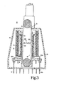
- Auxiliary transformer windings 202,203 and 204, along with power supply circuits 7, 8 and 9, respectively, generate the desired voltage levels for their associated load circuits. The construction of transformer 21 will be explained in greater detail later in conjunction with the description of FIGURE 3.
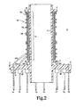
- FIGURE 2 shows a transformer winding coil form or bobbin 10, illustratively made of a plastic material, such as plastics sold under the names of Noryl or valox.
- Bobbin or coil form 10 comprises a base 11 and a cylindrical oody 12 about which transformer windings are wound.
- Bobbin 10. also incorporates an upper winding stop 13 and a lower winding stop 14 which contain the transformer windings within a winding region 15.
- Base 11 incorporates a plurality of radial elements 16, each of which illustratively incorporates an electrical terminal, designated 17a-17h.
- the interior of bobbin 10 is shaped to receive a magnetically permeable core (not shown).
- a plurality of transformer windings 20 are shown wound on bobbin 10. Each winding will comprise a plurality of wire turns having two terminals for coupling the winding to a load circuit. One terminal is coupled to respective ones of bobbin terminals 17a-17h.
- the wire turns that comprise each of the windings on bobbin 10 are shown in an exaggerated manner for illustrative purposes. The actual number of turns in each winding is determined using conventional transformer design criteria.
- Each of the transformer windings 20 is wound in layer fashion within winding region 15 on bobbin 10.
- the individual windings may each comprise one or more layers of wire turns, but in the assembly shown in FIGURE 1, each winding is illustratively comprised of only one layer of wire turns for simplicity. Additional windings may also be wound on bobbin 10.
- the wire turns that are designated in FIGURE 2 by the identifying numeral "1" comprise the wire turns of primary winding 201.
- the wire turns that are designated in FIGURE 2 by the identifying numerals "2", “3” and “4" comprises the wire turns of auxiliary windings 202, 203 and 204, respectively.
- Windings 201, 202, 203 and 204 are respectively connected to terminals 17f, 17c, 17b and 17a via conductors 201c, 202c, 203c and 204C.
- primary winding 201 and auxiliary windings 202, 203 and 204 are uniformly distributed over the winding region 25, such that the spacing between individual wire turns is substantially constant for a given winding.
- each of windings 202, 203 and 204 extend over the complete traverse (i.e., winding region 15) of the primary winding 201. Tnis permits a uniform or constant degree of magnetic coupling between each of windings 202, 203 and 204 and primary winding 201 over the entire length of the windings. This causes the primary winding 201 to be uniformly loaded by each of windings 202, 203 and 204.
- bobbin 10 comprises a portion of a television receiver or video monitor high voltage transformer, as shown in FIGURE 3, uniform loading or the primary winding by the auxiliary windings results in uniform loading of the tertiary or high voltge winding 23 by the primary winding 201, since energization of the auxiliary windings loads the primary winding,which is reflected to the tertiary winding 23.
- a constant network resonance from the primary winding to each coil of the transformer tertiary winding is maintained, which advantageously permits the tuning of the tertiary winding to a single harmonic pole, wnich may illustratively be a high harmonic of the order of the ninth harmonic or above.
- FIGURE 4 illustrates a typical insulated wire 35, which may be used to wind any of windings 201, 202, 203 or 204.
- Wire 35 comprises a conductive wire core 36 surrounded by an insulating jacket or coating 37. Because of the high AC voltage stress between wire turns of different windings, it is important that the thickness and electrical property requirements of insulating jacket 37 be carefully determined. Using wire that has more insulation than is necessary increases the size and cost of the transformer, and may degrade coupling between windings. Too little insulation increases the chance of arcing and transformer failure.
- the coupling energy between molecules of a material is a function of the material composition and the process used in its formation.
- the molecules of the wire insulation have all of their coupling poles coupled, making for very high resistance.
- Transformer 21 comprises bobbin 10 having windings 201, 202, 203 and 204 wound thereon.
- bobbin 10 Surrounding bobbin 10 is a tertiary winding bobbin 22, upon which is wound the high voltage or tertiary winding 23.
- the winding assemblies are disposed within a transformer housing 30 and are desirably potted within housing 30 with an epoxy compound 40.
- a high voltage or anode lead 31 is coupled to the high voltage end of tertiary winding 23 and supplies the high voltage level to the anode terminal of a cathode ray tube (not shown).
- the oreviously described transformer therefore incorporates advantageous winding techniques in which subsequent winding layers on the primary winding bobbin are wound directly over previous layers without intermediate layers of insulation,which optimizes power transfer and output impedance characteristics.
- the winding turns of the auxiliary windings are distributed evenly over the full traverse of the primary winding,which permits tuning of the transformer to a single harmonic, for example a high harmonic such as the ninth harmonic.
Landscapes
- Engineering & Computer Science (AREA)
- Power Engineering (AREA)
- Multimedia (AREA)
- Signal Processing (AREA)
- Coils Or Transformers For Communication (AREA)
- Details Of Television Scanning (AREA)
- Coils Of Transformers For General Uses (AREA)
- Details Of Indoor Wiring (AREA)
- Operating, Guiding And Securing Of Roll- Type Closing Members (AREA)
- Details Of Television Systems (AREA)
- Circuits Of Receivers In General (AREA)
Applications Claiming Priority (2)
| Application Number | Priority Date | Filing Date | Title |
|---|---|---|---|
| US717805 | 1985-03-29 | ||
| US06/717,805 US4654775A (en) | 1985-03-29 | 1985-03-29 | Transformer winding arrangement for a television apparatus |
Publications (3)
| Publication Number | Publication Date |
|---|---|
| EP0196857A2 true EP0196857A2 (de) | 1986-10-08 |
| EP0196857A3 EP0196857A3 (de) | 1988-08-03 |
| EP0196857B1 EP0196857B1 (de) | 1996-11-06 |
Family
ID=24883572
Family Applications (1)
| Application Number | Title | Priority Date | Filing Date |
|---|---|---|---|
| EP86302176A Expired - Lifetime EP0196857B1 (de) | 1985-03-29 | 1986-03-25 | Transformatorwicklungsanordnung, insbesondere für Videoanzeige |
Country Status (15)
| Country | Link |
|---|---|
| US (1) | US4654775A (de) |
| EP (1) | EP0196857B1 (de) |
| JP (1) | JP2598779B2 (de) |
| KR (1) | KR940000711B1 (de) |
| CN (1) | CN1017198B (de) |
| AT (1) | ATE145085T1 (de) |
| AU (1) | AU576069B2 (de) |
| CA (1) | CA1239199A (de) |
| DE (1) | DE3650581T2 (de) |
| DK (1) | DK143386A (de) |
| ES (1) | ES8707015A1 (de) |
| FI (1) | FI82341C (de) |
| MX (1) | MX162184A (de) |
| SG (1) | SG93768A1 (de) |
| ZA (1) | ZA862264B (de) |
Cited By (3)
| Publication number | Priority date | Publication date | Assignee | Title |
|---|---|---|---|---|
| EP0200567A2 (de) | 1985-05-03 | 1986-11-05 | Rca Licensing Corporation | Vorrichtung zum Fokussierungsabgleich einer Kathodenstrahlröhre |
| DE4127836A1 (de) * | 1991-08-22 | 1993-02-25 | Thomson Brandt Gmbh | Hochspannungstransformator fuer einen fernsehempfaenger |
| WO2016073291A1 (en) | 2014-11-03 | 2016-05-12 | Hubbell Incorporated | Intrinsically safe transformers |
Families Citing this family (5)
| Publication number | Priority date | Publication date | Assignee | Title |
|---|---|---|---|---|
| DE8519972U1 (de) * | 1985-07-10 | 1985-08-29 | Siemens AG, 1000 Berlin und 8000 München | Elektrische Verbinderleiste |
| US4967121A (en) * | 1987-05-27 | 1990-10-30 | Rca Licensing Corporation | Isolating high voltage transformer for video apparatus |
| US5430341A (en) * | 1992-09-28 | 1995-07-04 | Summer; Steven | Miniaturized power supply for an electroactive actuator |
| TW369654B (en) | 1997-07-07 | 1999-09-11 | Thomson Brandt Gmbh | Diode-split high-voltage transformer |
| US6788182B2 (en) * | 2002-09-03 | 2004-09-07 | Dupont Teijin Films U.S. Limited Partnership | Metalized polyester film with heat-seal layer on opposite side for flyback transformer application |
Family Cites Families (14)
| Publication number | Priority date | Publication date | Assignee | Title |
|---|---|---|---|---|
| US31119A (en) * | 1861-01-15 | Thomas hbgaety | ||
| US2878455A (en) * | 1956-02-28 | 1959-03-17 | Gen Electric | Three winding transformer |
| US2910529A (en) * | 1956-10-05 | 1959-10-27 | Raytheon Co | Transformer coupling of color signal |
| DE1538046A1 (de) * | 1966-01-14 | 1969-08-21 | Philips Patentverwaltung | Spule fuer einen Hochspannungstransformator geringer Leistung |
| US3652968A (en) * | 1971-01-26 | 1972-03-28 | Westinghouse Electric Corp | Telescoped electrical windings and method of making same |
| BE791522A (fr) * | 1971-11-18 | 1973-03-16 | Matsushita Electric Industrial Co Ltd | Transformateur haute tension associe a un circuit a diviation horizontale |
| US3886434A (en) * | 1973-09-07 | 1975-05-27 | Warwick Electronics Inc | Flyback transformer |
| US4086552A (en) * | 1974-10-21 | 1978-04-25 | U.S. Philips Corporation | High-voltage transformer comprising a foil winding |
| US3947749A (en) * | 1975-01-31 | 1976-03-30 | Hitachi, Ltd. | Apparatus for generating high voltage for cathode-ray tube |
| US4204263A (en) * | 1977-04-20 | 1980-05-20 | Denki Onkyo Co., Ltd. | Flyback transformer |
| US4229786A (en) * | 1977-09-26 | 1980-10-21 | Murata Manufacturing Co., Inc. | Fly-back transformer with a low ringing ratio |
| NL7713118A (nl) * | 1977-11-29 | 1979-05-31 | Philips Nv | Hoogspanningstransformator. |
| US4247889A (en) * | 1979-02-23 | 1981-01-27 | Blaupunkt-Werke Gmbh | High-voltage-secondary transformer, particularly television line transformer |
| JPS58119614A (ja) * | 1982-01-08 | 1983-07-16 | Sanyo Electric Co Ltd | フライバツクトランス |
-
1985
- 1985-03-29 US US06/717,805 patent/US4654775A/en not_active Expired - Fee Related
-
1986
- 1986-03-12 CN CN86101721A patent/CN1017198B/zh not_active Expired
- 1986-03-18 CA CA000504414A patent/CA1239199A/en not_active Expired
- 1986-03-21 FI FI861208A patent/FI82341C/fi not_active IP Right Cessation
- 1986-03-21 ES ES553225A patent/ES8707015A1/es not_active Expired
- 1986-03-24 AU AU55047/86A patent/AU576069B2/en not_active Ceased
- 1986-03-25 EP EP86302176A patent/EP0196857B1/de not_active Expired - Lifetime
- 1986-03-25 AT AT86302176T patent/ATE145085T1/de active
- 1986-03-25 DE DE3650581T patent/DE3650581T2/de not_active Expired - Fee Related
- 1986-03-25 SG SG9602476A patent/SG93768A1/en unknown
- 1986-03-26 ZA ZA862264A patent/ZA862264B/xx unknown
- 1986-03-26 MX MX2003A patent/MX162184A/es unknown
- 1986-03-26 DK DK143386A patent/DK143386A/da not_active IP Right Cessation
- 1986-03-27 JP JP61070637A patent/JP2598779B2/ja not_active Expired - Lifetime
- 1986-03-29 KR KR1019860002368A patent/KR940000711B1/ko not_active Expired - Fee Related
Cited By (4)
| Publication number | Priority date | Publication date | Assignee | Title |
|---|---|---|---|---|
| EP0200567A2 (de) | 1985-05-03 | 1986-11-05 | Rca Licensing Corporation | Vorrichtung zum Fokussierungsabgleich einer Kathodenstrahlröhre |
| DE4127836A1 (de) * | 1991-08-22 | 1993-02-25 | Thomson Brandt Gmbh | Hochspannungstransformator fuer einen fernsehempfaenger |
| WO2016073291A1 (en) | 2014-11-03 | 2016-05-12 | Hubbell Incorporated | Intrinsically safe transformers |
| EP3216034A4 (de) * | 2014-11-03 | 2018-07-04 | Hubbell Incorporated | Eigensichere transformatoren |
Also Published As
| Publication number | Publication date |
|---|---|
| SG93768A1 (en) | 2003-01-21 |
| FI861208L (fi) | 1986-09-30 |
| AU5504786A (en) | 1986-10-02 |
| EP0196857A3 (de) | 1988-08-03 |
| FI82341B (fi) | 1990-10-31 |
| DK143386D0 (da) | 1986-03-26 |
| ES8707015A1 (es) | 1987-07-01 |
| DK143386A (da) | 1986-09-30 |
| MX162184A (es) | 1991-04-08 |
| CN86101721A (zh) | 1986-09-24 |
| JP2598779B2 (ja) | 1997-04-09 |
| US4654775A (en) | 1987-03-31 |
| DE3650581T2 (de) | 1997-05-22 |
| ZA862264B (en) | 1986-11-26 |
| FI82341C (fi) | 1991-02-11 |
| AU576069B2 (en) | 1988-08-11 |
| JPS61230304A (ja) | 1986-10-14 |
| DE3650581D1 (de) | 1996-12-12 |
| EP0196857B1 (de) | 1996-11-06 |
| CA1239199A (en) | 1988-07-12 |
| KR860007814A (ko) | 1986-10-17 |
| ES553225A0 (es) | 1987-07-01 |
| KR940000711B1 (ko) | 1994-01-27 |
| CN1017198B (zh) | 1992-06-24 |
| ATE145085T1 (de) | 1996-11-15 |
| FI861208A0 (fi) | 1986-03-21 |
Similar Documents
| Publication | Publication Date | Title |
|---|---|---|
| EP0197698B1 (de) | Induktanzeinstellung für Transformatoren | |
| EP0196857B1 (de) | Transformatorwicklungsanordnung, insbesondere für Videoanzeige | |
| GB2045012A (en) | High voltage transformer rectifier | |
| GB2033669A (en) | Flyback transformer | |
| EP0307036B1 (de) | Transformator | |
| KR930005134B1 (ko) | 플라이백 트랜스포머 | |
| US5576681A (en) | High voltage transformer | |
| EP0043615A1 (de) | Hochspannungstransformator | |
| US5973584A (en) | High-voltage transformer for a television receiver | |
| JPH08115829A (ja) | コンバータトランス | |
| JPH1055898A (ja) | X線装置 | |
| RU2054721C1 (ru) | Трансформатор строчной развертки | |
| EP0286980A1 (de) | Hochspannungstransformator | |
| CN87103749A (zh) | 电气变换器 | |
| KR900001071B1 (ko) | 플라이백트랜스포머 | |
| EP0851443A1 (de) | Diodensplit-Hochspannungstransformator mit Halb-Lagenwicklungen | |
| US20020075612A1 (en) | High voltage transformer with over voltage protection, and method for over voltage protection | |
| HK1000199B (en) | Inductance adjustment for transformers | |
| JPS6118898B2 (de) | ||
| NL8300093A (nl) | Hoogspanningstransformator. | |
| JPS6057910A (ja) | 樹脂モ−ルドコイル | |
| JPS61145810A (ja) | ガス絶縁変圧器 | |
| JPS61142713A (ja) | フライバツクトランス | |
| KR19990026247A (ko) | 플라이백 트랜스포머 |
Legal Events
| Date | Code | Title | Description |
|---|---|---|---|
| PUAI | Public reference made under article 153(3) epc to a published international application that has entered the european phase |
Free format text: ORIGINAL CODE: 0009012 |
|
| AK | Designated contracting states |
Kind code of ref document: A2 Designated state(s): AT DE FR GB IT SE |
|
| RAP1 | Party data changed (applicant data changed or rights of an application transferred) |
Owner name: RCA LICENSING CORPORATION |
|
| PUAL | Search report despatched |
Free format text: ORIGINAL CODE: 0009013 |
|
| AK | Designated contracting states |
Kind code of ref document: A3 Designated state(s): AT DE FR GB IT SE |
|
| 17P | Request for examination filed |
Effective date: 19890109 |
|
| 17Q | First examination report despatched |
Effective date: 19911001 |
|
| RAP1 | Party data changed (applicant data changed or rights of an application transferred) |
Owner name: RCA THOMSON LICENSING CORPORATION |
|
| APAB | Appeal dossier modified |
Free format text: ORIGINAL CODE: EPIDOS NOAPE |
|
| GRAG | Despatch of communication of intention to grant |
Free format text: ORIGINAL CODE: EPIDOS AGRA |
|
| GRAH | Despatch of communication of intention to grant a patent |
Free format text: ORIGINAL CODE: EPIDOS IGRA |
|
| GRAH | Despatch of communication of intention to grant a patent |
Free format text: ORIGINAL CODE: EPIDOS IGRA |
|
| GRAA | (expected) grant |
Free format text: ORIGINAL CODE: 0009210 |
|
| AK | Designated contracting states |
Kind code of ref document: B1 Designated state(s): AT DE FR GB IT SE |
|
| PG25 | Lapsed in a contracting state [announced via postgrant information from national office to epo] |
Ref country code: AT Effective date: 19961106 |
|
| REF | Corresponds to: |
Ref document number: 145085 Country of ref document: AT Date of ref document: 19961115 Kind code of ref document: T |
|
| REF | Corresponds to: |
Ref document number: 3650581 Country of ref document: DE Date of ref document: 19961212 |
|
| ITF | It: translation for a ep patent filed | ||
| PG25 | Lapsed in a contracting state [announced via postgrant information from national office to epo] |
Ref country code: SE Effective date: 19970206 |
|
| ET | Fr: translation filed | ||
| PLBE | No opposition filed within time limit |
Free format text: ORIGINAL CODE: 0009261 |
|
| STAA | Information on the status of an ep patent application or granted ep patent |
Free format text: STATUS: NO OPPOSITION FILED WITHIN TIME LIMIT |
|
| 26N | No opposition filed | ||
| PGFP | Annual fee paid to national office [announced via postgrant information from national office to epo] |
Ref country code: FR Payment date: 19990201 Year of fee payment: 14 |
|
| REG | Reference to a national code |
Ref country code: GB Ref legal event code: 732E |
|
| PG25 | Lapsed in a contracting state [announced via postgrant information from national office to epo] |
Ref country code: FR Free format text: LAPSE BECAUSE OF NON-PAYMENT OF DUE FEES Effective date: 20001130 |
|
| REG | Reference to a national code |
Ref country code: FR Ref legal event code: ST |
|
| PGFP | Annual fee paid to national office [announced via postgrant information from national office to epo] |
Ref country code: GB Payment date: 20010126 Year of fee payment: 16 |
|
| PGFP | Annual fee paid to national office [announced via postgrant information from national office to epo] |
Ref country code: DE Payment date: 20010427 Year of fee payment: 16 |
|
| REG | Reference to a national code |
Ref country code: GB Ref legal event code: IF02 |
|
| PG25 | Lapsed in a contracting state [announced via postgrant information from national office to epo] |
Ref country code: GB Free format text: LAPSE BECAUSE OF NON-PAYMENT OF DUE FEES Effective date: 20020325 |
|
| PG25 | Lapsed in a contracting state [announced via postgrant information from national office to epo] |
Ref country code: DE Free format text: LAPSE BECAUSE OF NON-PAYMENT OF DUE FEES Effective date: 20021001 |
|
| PG25 | Lapsed in a contracting state [announced via postgrant information from national office to epo] |
Ref country code: IT Free format text: LAPSE BECAUSE OF NON-PAYMENT OF DUE FEES;WARNING: LAPSES OF ITALIAN PATENTS WITH EFFECTIVE DATE BEFORE 2007 MAY HAVE OCCURRED AT ANY TIME BEFORE 2007. THE CORRECT EFFECTIVE DATE MAY BE DIFFERENT FROM THE ONE RECORDED. Effective date: 20050325 |
|
| APAH | Appeal reference modified |
Free format text: ORIGINAL CODE: EPIDOSCREFNO |