EP0196961B1 - Sonnenblende für Fahrzeuge - Google Patents
Sonnenblende für Fahrzeuge Download PDFInfo
- Publication number
- EP0196961B1 EP0196961B1 EP86400569A EP86400569A EP0196961B1 EP 0196961 B1 EP0196961 B1 EP 0196961B1 EP 86400569 A EP86400569 A EP 86400569A EP 86400569 A EP86400569 A EP 86400569A EP 0196961 B1 EP0196961 B1 EP 0196961B1
- Authority
- EP
- European Patent Office
- Prior art keywords
- mirror
- support
- sun visor
- shield
- strips
- Prior art date
- Legal status (The legal status is an assumption and is not a legal conclusion. Google has not performed a legal analysis and makes no representation as to the accuracy of the status listed.)
- Expired
Links
- 239000000463 material Substances 0.000 claims description 5
- 229920003023 plastic Polymers 0.000 claims description 5
- 239000004033 plastic Substances 0.000 claims description 5
- 230000002093 peripheral effect Effects 0.000 claims description 4
- 229920002292 Nylon 6 Polymers 0.000 claims description 2
- 239000011521 glass Substances 0.000 claims description 2
- 230000002787 reinforcement Effects 0.000 claims 3
- 239000004800 polyvinyl chloride Substances 0.000 description 9
- 229920000915 polyvinyl chloride Polymers 0.000 description 8
- 239000011248 coating agent Substances 0.000 description 7
- 238000000576 coating method Methods 0.000 description 7
- 239000006260 foam Substances 0.000 description 4
- 210000002105 tongue Anatomy 0.000 description 4
- 238000004519 manufacturing process Methods 0.000 description 3
- 239000002184 metal Substances 0.000 description 3
- 239000004743 Polypropylene Substances 0.000 description 1
- 239000000470 constituent Substances 0.000 description 1
- 230000007423 decrease Effects 0.000 description 1
- 230000007547 defect Effects 0.000 description 1
- 238000002347 injection Methods 0.000 description 1
- 239000007924 injection Substances 0.000 description 1
- 238000003780 insertion Methods 0.000 description 1
- 230000037431 insertion Effects 0.000 description 1
- 238000009434 installation Methods 0.000 description 1
- 238000000034 method Methods 0.000 description 1
- -1 polypropylene Polymers 0.000 description 1
- 229920001155 polypropylene Polymers 0.000 description 1
- 238000003466 welding Methods 0.000 description 1
Images


Classifications
-
- B—PERFORMING OPERATIONS; TRANSPORTING
- B60—VEHICLES IN GENERAL
- B60J—WINDOWS, WINDSCREENS, NON-FIXED ROOFS, DOORS, OR SIMILAR DEVICES FOR VEHICLES; REMOVABLE EXTERNAL PROTECTIVE COVERINGS SPECIALLY ADAPTED FOR VEHICLES
- B60J3/00—Antiglare equipment associated with windows or windscreens; Sun visors for vehicles
- B60J3/02—Antiglare equipment associated with windows or windscreens; Sun visors for vehicles adjustable in position
- B60J3/0204—Sun visors
- B60J3/0278—Sun visors structure of the body
- B60J3/0282—Sun visors structure of the body specially adapted for a courtesy mirror
Definitions
- the present invention relates to a sun visor for motor vehicles, of the type mentioned in the preamble of claim 1. (See document DE-A-2220711)
- the mirror is fixed to the PVC covering by means of a metal or plastic frame which is itself held in place by a rigid PVC plate, welded to the covering PVC. After installation on the mirror, the legs of the frame are folded down.
- This device is expensive because it requires a large workforce, intermediate stocks as well as handling.
- documents DE-A-2 619 844 and DE-A-2 220 711 describe sun visors, the mirror of which is arranged in a removable support which can be fixed in a housing by clipping on retaining means integral with the screen of the sun visor.
- the mirrors with their support frames must be placed in the sun visor before placing the final covering sheet, which is then welded to the support frame or to the mirror itself.
- the sun visor is characterized by the means mentioned in the characterizing part of claim 1.
- the assembly of the mirror previously slipped into its support frame is done after the final coating has been put in place, is very simple and rapid, which significantly reduces the labor required.
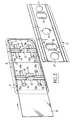
- the sun visor shown in Figures 1 to 3 is intended for motor vehicles, and it comprises a screen 1, preferably made of injected foam, covered with a coating 2 of a suitable plastic material such as a sheet of polyvinyl chloride (PVC) and provided with a mirror 3 fixed in a housing 4 provided in the screen 1.
- a screen 1 preferably made of injected foam
- a coating 2 of a suitable plastic material such as a sheet of polyvinyl chloride (PVC) and provided with a mirror 3 fixed in a housing 4 provided in the screen 1.
- PVC polyvinyl chloride
- An axis 5 the two ends of which are embedded in the screen 1, allows the sun visor to be articulated to the roof of the vehicle.
- the mirror 3 is arranged in a removable support 6 which can be fixed in the housing 4 by clipping onto retaining means 7 secured to the screen 1.
- the support 7 is constituted by a frame whose periphery matches the outline of the mirror 3, which is rectangular in this embodiment, and can be slid into the frame 6.
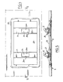
- This therefore includes a peripheral rim 8 conforming to the outline of the mirror 3, as well as a rib 9 perpendicular to the rim 8 and which extends over the entire periphery thereof with the exception of a small side, to which therefore corresponds an opening (FIG. 2) making it possible to introduce the mirror 3 into the frame 6.
- the long sides of the rim 8 are connected by two transverse bars 11 each provided with a pair of lugs 12 oriented perpendicular to the general plane of the bars 11 and the rim 8, as well as a pair of longitudinal tongues 13, parallel to each other and extending substantially in the same plane as the rim 8 and the bars 11.
- Chamfers 13a are provided on the ends of the tongues 13 facing the insertion opening of the mirror 3, which can thus slide over the chamfered ends 13a during its introduction into the frame 6, between the internal periphery of the rim 8 on which it is held in abutment by the tongues 13.
- the latter also for this purpose comprise ends 13b formed on the other side of the chamfers 13a with respect to the bars 11.
- the two pairs of legs 12 are provided at their ends with chamfered projections 14 making it possible to clip the legs 12, by elastic spacing of the latter, on the opposite edges 15 of two openings 16 each formed opposite a pair of legs 12 in a rigid constituent insert the aforementioned means 7 for retaining the support 6 and the mirror 3.
- the insert 7, preferably metallic, is pierced, in this embodiment, with three circular holes 17 intended to be crossed by bosses 18, 19 (FIG. 1) of injected foam serving as supports for the mirror 3.
- the metal insert 7 is placed at the bottom of the housing 4 and covered with a film of foam then, with the assembly of the screen 1, is covered by the coating. 2 of PVC.
- the mirror 3 is on its side slid into the frame 6, between the tongues 13 and the flange 8 on which it is pressed. After which it only remains to snap the legs 12 by their projections 14 on the opposite edges 15 of the openings 16, the inclined faces of the projections 14 sliding on these edges, while the legs 12 approach one of the other, then move away elastically by gripping the insert 7 through the sheet 2.
- the mirror 3 is then in place.
- the support frame 6 is made of a plastic material having good temperature resistance, for example made of glass-filled polyamide 6/6, which withstands temperatures which may exceed 105 ° C.
- the means for retaining the armature 6 are constituted by two plates 21 made in one piece with a half-shell 22 constituting one half of the screen of the sun visor in accordance with French patent 81 18 233 of the Applicant, this half-shell being produced for example from polypropylene.
- the two bars 21 are arranged transversely in a housing 23 of the half-shell 22, and are each pierced with an opening 24 on the opposite edges 24a, which can snap the two pairs of elastic tabs 12 (Fig. 5) .
- the mounting method is the same as in the first embodiment, and the internal periphery of the peripheral rim 8 comes to bear on the corresponding periphery of the housing 23.
Landscapes
- Engineering & Computer Science (AREA)
- Mechanical Engineering (AREA)
- Mirrors, Picture Frames, Photograph Stands, And Related Fastening Devices (AREA)
- Optical Elements Other Than Lenses (AREA)
- Rear-View Mirror Devices That Are Mounted On The Exterior Of The Vehicle (AREA)
Claims (2)
Applications Claiming Priority (2)
| Application Number | Priority Date | Filing Date | Title |
|---|---|---|---|
| FR8504427A FR2579150B1 (fr) | 1985-03-25 | 1985-03-25 | Pare-soleil pour vehicule automobile |
| FR8504427 | 1985-03-25 |
Publications (2)
| Publication Number | Publication Date |
|---|---|
| EP0196961A1 EP0196961A1 (de) | 1986-10-08 |
| EP0196961B1 true EP0196961B1 (de) | 1988-10-26 |
Family
ID=9317551
Family Applications (1)
| Application Number | Title | Priority Date | Filing Date |
|---|---|---|---|
| EP86400569A Expired EP0196961B1 (de) | 1985-03-25 | 1986-03-18 | Sonnenblende für Fahrzeuge |
Country Status (9)
| Country | Link |
|---|---|
| US (1) | US4685723A (de) |
| EP (1) | EP0196961B1 (de) |
| JP (1) | JPS61257319A (de) |
| BR (1) | BR8601310A (de) |
| CA (1) | CA1270281A (de) |
| DE (1) | DE3660994D1 (de) |
| ES (1) | ES293342Y (de) |
| FR (1) | FR2579150B1 (de) |
| MX (1) | MX167483B (de) |
Families Citing this family (19)
| Publication number | Priority date | Publication date | Assignee | Title |
|---|---|---|---|---|
| US4791537A (en) * | 1984-07-02 | 1988-12-13 | Irvin Industries, Inc. | Vehicle accessory assembly with sliding door for mounting on a visor or other interior panel |
| US4711483A (en) * | 1986-01-21 | 1987-12-08 | Irvin Industries, Inc. | Motor vehicle visor with removable mirror assembly |
| US4858983A (en) * | 1988-04-04 | 1989-08-22 | White Jay E | Sun visor frame and mounting structure |
| ES2006885A6 (es) * | 1988-04-08 | 1989-05-16 | Gabas Cebollero Carlos | Espejo para visera parasol de automoviles. |
| GB2218059B (en) * | 1988-04-30 | 1991-09-11 | Austin Rover Group | A sun visor |
| US4866579A (en) * | 1988-05-23 | 1989-09-12 | Prince Corporation | Snap-in mirror package |
| US4922391A (en) * | 1989-01-12 | 1990-05-01 | Prince Corporation | Vanity mirror package |
| SE465719B (sv) * | 1990-01-31 | 1991-10-21 | Autopart Sweden Ab | Solskydd foer motorfordon |
| DE4023243C1 (de) * | 1990-07-21 | 1991-11-21 | Gebr. Happich Gmbh, 5600 Wuppertal, De | |
| US5338082A (en) * | 1992-04-15 | 1994-08-16 | Plasta Fiber Industries Corp. | Apparatus for securing fabric to a visor |
| US5301994A (en) * | 1992-10-14 | 1994-04-12 | Plasta Fiber Industries Corp. | Dual synchronous opening mirror doors for sun visors |
| US5441325A (en) * | 1993-07-07 | 1995-08-15 | Prince Corporation | Vanity mirror with opposed sliding covers |
| DE19635684B4 (de) * | 1996-09-03 | 2004-09-30 | Johnson Controls Interiors Gmbh & Co. Kg | Sonnenblende für Fahrzeuge |
| US6254168B1 (en) | 2000-01-31 | 2001-07-03 | Crotty Corporation | Sun visor with vanity mirror |
| US6698815B1 (en) * | 2002-10-02 | 2004-03-02 | Grupo Antolin Ingenieria, S.A. | Sun visor with mirror assembly |
| DE10340079B4 (de) * | 2003-08-30 | 2008-07-03 | Johnson Controls Interiors Gmbh & Co. Kg | Sonnenblende |
| DE502008000304D1 (de) * | 2008-03-25 | 2010-02-25 | Smr Patents Sarl | Sonnenblende mit Plastikspiegel |
| DE102017004901A1 (de) | 2017-05-20 | 2017-11-16 | Daimler Ag | Sonnenblende für ein Fahrzeug und Verfahren zur Montage einer solchen Sonnenblende |
| ES1225564Y (es) * | 2018-12-17 | 2019-05-20 | Grupo Antolin Ingenieria S A U | Parasol |
Family Cites Families (7)
| Publication number | Priority date | Publication date | Assignee | Title |
|---|---|---|---|---|
| US3843236A (en) * | 1972-11-24 | 1974-10-22 | Donnelly Mirrors Inc | Shatter-resistant mirror mounting |
| DE2619844C3 (de) * | 1976-05-05 | 1981-03-26 | Gebr. Happich Gmbh, 42285 Wuppertal | Sonnenblende, insbesondere für Fahrzeuge |
| US4068930A (en) * | 1976-12-27 | 1978-01-17 | Prince Corporation | Visor assembly and covered vanity mirror |
| JPS596515B2 (ja) * | 1977-03-17 | 1984-02-13 | 松下電器産業株式会社 | 集積回路装置 |
| US4275916A (en) * | 1979-04-19 | 1981-06-30 | Prince Corporation | Visor with storage compartment |
| FR2513578A1 (fr) * | 1981-09-28 | 1983-04-01 | Mecanismes Comp Ind De | Pare-soleil, notamment pour vehicule automobile |
| US4494789A (en) * | 1983-05-02 | 1985-01-22 | Prince Corporation | Visor covering |
-
1985
- 1985-03-25 FR FR8504427A patent/FR2579150B1/fr not_active Expired
-
1986
- 1986-03-18 EP EP86400569A patent/EP0196961B1/de not_active Expired
- 1986-03-18 DE DE8686400569T patent/DE3660994D1/de not_active Expired
- 1986-03-24 BR BR8601310A patent/BR8601310A/pt not_active IP Right Cessation
- 1986-03-24 MX MX001962A patent/MX167483B/es unknown
- 1986-03-24 CA CA000504939A patent/CA1270281A/en not_active Expired - Fee Related
- 1986-03-24 ES ES1986293342U patent/ES293342Y/es not_active Expired
- 1986-03-25 JP JP61067003A patent/JPS61257319A/ja active Pending
- 1986-03-25 US US06/843,527 patent/US4685723A/en not_active Expired - Lifetime
Also Published As
| Publication number | Publication date |
|---|---|
| BR8601310A (pt) | 1986-12-02 |
| ES293342U (es) | 1986-08-01 |
| JPS61257319A (ja) | 1986-11-14 |
| FR2579150A1 (fr) | 1986-09-26 |
| DE3660994D1 (en) | 1988-12-01 |
| ES293342Y (es) | 1987-09-16 |
| CA1270281A (en) | 1990-06-12 |
| EP0196961A1 (de) | 1986-10-08 |
| MX167483B (es) | 1993-03-25 |
| US4685723A (en) | 1987-08-11 |
| FR2579150B1 (fr) | 1987-06-26 |
Similar Documents
| Publication | Publication Date | Title |
|---|---|---|
| EP0196961B1 (de) | Sonnenblende für Fahrzeuge | |
| FR2682072A1 (fr) | Obturateur a souder par collage pour ouverture pratiquee dans une tole, notamment de carrosserie automobile. | |
| EP0706159B1 (de) | Vorrichtung zur Kennzeichnung von insbesondere einer elektrischen Leitung oder einer Reihenklemme | |
| FR2793741A1 (fr) | Dispositif de fixation d'un radiateur sur un support d'un vehicule | |
| WO2018150125A1 (fr) | Interface de connexion électrique d'un dispositif de chauffage électrique pour véhicule automobile | |
| EP0829689A1 (de) | Abdichtung für Sperrungsvorrichtung für einen Lüftungskanal, insbesondere Brandschutzklappe oder Entlüftungsklappe | |
| FR2943017A1 (fr) | Profile pour element de fermeture de benne de vehicule et element de fermeture correspondant | |
| EP2585342B1 (de) | Zwischenbefestigungsteil für eine fahrzeugverkleidung | |
| FR2727186A1 (fr) | Habillage pour chemin de cables en fils, et chemin de cables comportant un tel habillage | |
| EP1666309B1 (de) | Clip zur Befestigung einer Dachverkleidung eines Fahrzeuges, Einheiten aus solchen Clips und einer Dachverkleidung sowie damit ausgestattetes Fahrzeug | |
| FR3058502B1 (fr) | Dispositif de montage sans vis d'un boitier de commande de projecteur sur ledit projecteur | |
| EP1164676B1 (de) | Vorrichtung zur Befestigung eines elektrischen Geräts auf einem Kabelkanal | |
| FR2868371A1 (fr) | Ensemble de montage d'une barre de toit longitudinale sur un toit d'un vehicule automobile | |
| EP0547929B1 (de) | Elektrische Anschlussbuchse, insbesondere für Kraftfahrzeuge | |
| EP1470942B1 (de) | Anordnung für die Befestigung eines Trägers für einen Sonnenvorhang | |
| FR2544411A1 (fr) | Dispositif de fixation a ecrou retenu en une seule piece | |
| FR2713170A1 (fr) | Porte-plaque minéralogique pour véhicule automobile. | |
| BE1006912A3 (fr) | Entretoise pour coffrets pour appareils electriques a disposer cote a cote. | |
| EP2050603B1 (de) | Rollo mit Aufwickelvorrichtung für Kraftfahrzeug, das mit einem mit Clips versehenen Befestigungssystem auf dem Rahmen ausgestattet ist, entsprechender Rahmen und entsprechendes Fahrzeug | |
| EP1432091A1 (de) | Kupplungsgarnitur für einen Kabelrinnesockel | |
| EP1044849A1 (de) | Befestigungselement aus geformtem Kunststoff für Automobilbau | |
| FR2917794A1 (fr) | Dispositif de fixation inviolable d'une piece dans une decoupe prevue sur une structure. | |
| WO2026027407A1 (fr) | Système de fixation sur un grillage en treillis | |
| EP1486402A1 (de) | Fahrzeugteil aus Kunststoff und dessen Zusammenbau mit einem anderem Fahrzeugteil | |
| EP4666004A1 (de) | Beleuchtungs- und/oder signalvorrichtung für kraftfahrzeuge mit einer anordnung von masken |
Legal Events
| Date | Code | Title | Description |
|---|---|---|---|
| PUAI | Public reference made under article 153(3) epc to a published international application that has entered the european phase |
Free format text: ORIGINAL CODE: 0009012 |
|
| AK | Designated contracting states |
Kind code of ref document: A1 Designated state(s): DE GB IT SE |
|
| 17P | Request for examination filed |
Effective date: 19870116 |
|
| RAP1 | Party data changed (applicant data changed or rights of an application transferred) |
Owner name: ROCKWELL-CIM |
|
| 17Q | First examination report despatched |
Effective date: 19870702 |
|
| ITF | It: translation for a ep patent filed | ||
| GRAA | (expected) grant |
Free format text: ORIGINAL CODE: 0009210 |
|
| AK | Designated contracting states |
Kind code of ref document: B1 Designated state(s): DE GB IT SE |
|
| REF | Corresponds to: |
Ref document number: 3660994 Country of ref document: DE Date of ref document: 19881201 |
|
| GBT | Gb: translation of ep patent filed (gb section 77(6)(a)/1977) | ||
| PLBE | No opposition filed within time limit |
Free format text: ORIGINAL CODE: 0009261 |
|
| STAA | Information on the status of an ep patent application or granted ep patent |
Free format text: STATUS: NO OPPOSITION FILED WITHIN TIME LIMIT |
|
| 26N | No opposition filed | ||
| PGFP | Annual fee paid to national office [announced via postgrant information from national office to epo] |
Ref country code: GB Payment date: 19930312 Year of fee payment: 8 |
|
| PGFP | Annual fee paid to national office [announced via postgrant information from national office to epo] |
Ref country code: SE Payment date: 19930323 Year of fee payment: 8 |
|
| ITTA | It: last paid annual fee | ||
| PG25 | Lapsed in a contracting state [announced via postgrant information from national office to epo] |
Ref country code: GB Effective date: 19940318 |
|
| PG25 | Lapsed in a contracting state [announced via postgrant information from national office to epo] |
Ref country code: SE Free format text: LAPSE BECAUSE OF NON-PAYMENT OF DUE FEES Effective date: 19940319 |
|
| GBPC | Gb: european patent ceased through non-payment of renewal fee |
Effective date: 19940318 |
|
| EUG | Se: european patent has lapsed |
Ref document number: 86400569.9 Effective date: 19941010 |
|
| PGFP | Annual fee paid to national office [announced via postgrant information from national office to epo] |
Ref country code: DE Payment date: 19950220 Year of fee payment: 10 |
|
| PG25 | Lapsed in a contracting state [announced via postgrant information from national office to epo] |
Ref country code: DE Effective date: 19961203 |
|
| PG25 | Lapsed in a contracting state [announced via postgrant information from national office to epo] |
Ref country code: IT Free format text: LAPSE BECAUSE OF NON-PAYMENT OF DUE FEES;WARNING: LAPSES OF ITALIAN PATENTS WITH EFFECTIVE DATE BEFORE 2007 MAY HAVE OCCURRED AT ANY TIME BEFORE 2007. THE CORRECT EFFECTIVE DATE MAY BE DIFFERENT FROM THE ONE RECORDED. Effective date: 20050318 |