EP0197156A1 - Appareil et traitement esthetique et benefique pour la sante utilisant des courants d'eau - Google Patents
Appareil et traitement esthetique et benefique pour la sante utilisant des courants d'eau Download PDFInfo
- Publication number
- EP0197156A1 EP0197156A1 EP85904877A EP85904877A EP0197156A1 EP 0197156 A1 EP0197156 A1 EP 0197156A1 EP 85904877 A EP85904877 A EP 85904877A EP 85904877 A EP85904877 A EP 85904877A EP 0197156 A1 EP0197156 A1 EP 0197156A1
- Authority
- EP
- European Patent Office
- Prior art keywords
- water current
- slimming
- beauty
- health promotion
- current type
- Prior art date
- Legal status (The legal status is an assumption and is not a legal conclusion. Google has not performed a legal analysis and makes no representation as to the accuracy of the status listed.)
- Withdrawn
Links
- XLYOFNOQVPJJNP-UHFFFAOYSA-N water Substances O XLYOFNOQVPJJNP-UHFFFAOYSA-N 0.000 title claims abstract description 183
- 238000002560 therapeutic procedure Methods 0.000 title abstract 2
- 230000036541 health Effects 0.000 claims abstract description 64
- 238000011282 treatment Methods 0.000 claims abstract description 38
- 238000000034 method Methods 0.000 claims abstract description 34
- 230000003796 beauty Effects 0.000 claims description 61
- 238000011144 upstream manufacturing Methods 0.000 claims description 31
- 230000007246 mechanism Effects 0.000 claims description 21
- 230000004936 stimulating effect Effects 0.000 claims description 19
- 239000003795 chemical substances by application Substances 0.000 claims description 3
- 230000035764 nutrition Effects 0.000 claims description 3
- 235000016709 nutrition Nutrition 0.000 claims description 3
- 239000002537 cosmetic Substances 0.000 claims description 2
- 230000001737 promoting effect Effects 0.000 claims description 2
- 238000012549 training Methods 0.000 abstract description 18
- 210000004003 subcutaneous fat Anatomy 0.000 abstract description 2
- 238000002474 experimental method Methods 0.000 description 42
- 210000001624 hip Anatomy 0.000 description 25
- 210000000689 upper leg Anatomy 0.000 description 21
- 230000000694 effects Effects 0.000 description 18
- 230000036544 posture Effects 0.000 description 17
- 238000012986 modification Methods 0.000 description 10
- 230000004048 modification Effects 0.000 description 10
- 238000010276 construction Methods 0.000 description 9
- 230000006870 function Effects 0.000 description 9
- 230000015556 catabolic process Effects 0.000 description 7
- 239000006260 foam Substances 0.000 description 6
- 238000009434 installation Methods 0.000 description 6
- 238000005192 partition Methods 0.000 description 6
- 230000008901 benefit Effects 0.000 description 5
- 238000007796 conventional method Methods 0.000 description 5
- 208000002193 Pain Diseases 0.000 description 4
- 230000037213 diet Effects 0.000 description 4
- 235000005911 diet Nutrition 0.000 description 4
- 230000033001 locomotion Effects 0.000 description 4
- 238000004519 manufacturing process Methods 0.000 description 4
- 230000036407 pain Effects 0.000 description 4
- 230000003134 recirculating effect Effects 0.000 description 4
- 230000009467 reduction Effects 0.000 description 4
- 230000000638 stimulation Effects 0.000 description 4
- 238000012360 testing method Methods 0.000 description 4
- 229910000831 Steel Inorganic materials 0.000 description 3
- 210000001217 buttock Anatomy 0.000 description 3
- 238000007599 discharging Methods 0.000 description 3
- 238000010438 heat treatment Methods 0.000 description 3
- 210000002751 lymph Anatomy 0.000 description 3
- 238000005259 measurement Methods 0.000 description 3
- 238000007493 shaping process Methods 0.000 description 3
- 239000010959 steel Substances 0.000 description 3
- -1 acryl Chemical group 0.000 description 2
- 238000003287 bathing Methods 0.000 description 2
- 230000036772 blood pressure Effects 0.000 description 2
- 244000309466 calf Species 0.000 description 2
- 238000011161 development Methods 0.000 description 2
- 201000010099 disease Diseases 0.000 description 2
- 208000037265 diseases, disorders, signs and symptoms Diseases 0.000 description 2
- 239000013013 elastic material Substances 0.000 description 2
- 210000004907 gland Anatomy 0.000 description 2
- 239000011521 glass Substances 0.000 description 2
- 238000012423 maintenance Methods 0.000 description 2
- 239000000463 material Substances 0.000 description 2
- 230000003340 mental effect Effects 0.000 description 2
- 239000002184 metal Substances 0.000 description 2
- 238000003825 pressing Methods 0.000 description 2
- 230000004800 psychological effect Effects 0.000 description 2
- 238000005406 washing Methods 0.000 description 2
- 206010010774 Constipation Diseases 0.000 description 1
- 102000004190 Enzymes Human genes 0.000 description 1
- 108090000790 Enzymes Proteins 0.000 description 1
- 235000012364 Peperomia pellucida Nutrition 0.000 description 1
- 240000007711 Peperomia pellucida Species 0.000 description 1
- 208000013738 Sleep Initiation and Maintenance disease Diseases 0.000 description 1
- 208000027418 Wounds and injury Diseases 0.000 description 1
- 239000008186 active pharmaceutical agent Substances 0.000 description 1
- 230000002411 adverse Effects 0.000 description 1
- 235000019789 appetite Nutrition 0.000 description 1
- 230000036528 appetite Effects 0.000 description 1
- 239000007844 bleaching agent Substances 0.000 description 1
- 238000009530 blood pressure measurement Methods 0.000 description 1
- 210000000746 body region Anatomy 0.000 description 1
- 230000008859 change Effects 0.000 description 1
- 239000012459 cleaning agent Substances 0.000 description 1
- 238000002485 combustion reaction Methods 0.000 description 1
- 238000012790 confirmation Methods 0.000 description 1
- 230000006378 damage Effects 0.000 description 1
- 238000000354 decomposition reaction Methods 0.000 description 1
- 230000003247 decreasing effect Effects 0.000 description 1
- 238000001514 detection method Methods 0.000 description 1
- 238000009792 diffusion process Methods 0.000 description 1
- 239000003814 drug Substances 0.000 description 1
- 229940079593 drug Drugs 0.000 description 1
- 229940088679 drug related substance Drugs 0.000 description 1
- 230000008030 elimination Effects 0.000 description 1
- 238000003379 elimination reaction Methods 0.000 description 1
- 239000012530 fluid Substances 0.000 description 1
- 230000002070 germicidal effect Effects 0.000 description 1
- 230000006872 improvement Effects 0.000 description 1
- 208000014674 injury Diseases 0.000 description 1
- 206010022437 insomnia Diseases 0.000 description 1
- 238000010884 ion-beam technique Methods 0.000 description 1
- 150000002500 ions Chemical class 0.000 description 1
- 210000003127 knee Anatomy 0.000 description 1
- 238000010412 laundry washing Methods 0.000 description 1
- 210000003205 muscle Anatomy 0.000 description 1
- 230000003387 muscular Effects 0.000 description 1
- 238000012856 packing Methods 0.000 description 1
- 239000012188 paraffin wax Substances 0.000 description 1
- 238000011056 performance test Methods 0.000 description 1
- 230000035479 physiological effects, processes and functions Effects 0.000 description 1
- 229920000915 polyvinyl chloride Polymers 0.000 description 1
- 239000004800 polyvinyl chloride Substances 0.000 description 1
- 230000002829 reductive effect Effects 0.000 description 1
- 238000011160 research Methods 0.000 description 1
- 230000004044 response Effects 0.000 description 1
- 230000025508 response to water Effects 0.000 description 1
- 230000000717 retained effect Effects 0.000 description 1
- 230000002441 reversible effect Effects 0.000 description 1
- 230000028327 secretion Effects 0.000 description 1
- 210000004872 soft tissue Anatomy 0.000 description 1
- 230000005236 sound signal Effects 0.000 description 1
- 229910001220 stainless steel Inorganic materials 0.000 description 1
- 239000010935 stainless steel Substances 0.000 description 1
Images


Classifications
-
- A—HUMAN NECESSITIES
- A63—SPORTS; GAMES; AMUSEMENTS
- A63B—APPARATUS FOR PHYSICAL TRAINING, GYMNASTICS, SWIMMING, CLIMBING, OR FENCING; BALL GAMES; TRAINING EQUIPMENT
- A63B24/00—Electric or electronic controls for exercising apparatus of preceding groups; Controlling or monitoring of exercises, sportive games, training or athletic performances
- A63B24/0003—Analysing the course of a movement or motion sequences during an exercise or trainings sequence, e.g. swing for golf or tennis
-
- A—HUMAN NECESSITIES
- A61—MEDICAL OR VETERINARY SCIENCE; HYGIENE
- A61H—PHYSICAL THERAPY APPARATUS, e.g. DEVICES FOR LOCATING OR STIMULATING REFLEX POINTS IN THE BODY; ARTIFICIAL RESPIRATION; MASSAGE; BATHING DEVICES FOR SPECIAL THERAPEUTIC OR HYGIENIC PURPOSES OR SPECIFIC PARTS OF THE BODY
- A61H15/00—Massage by means of rollers, balls, e.g. inflatable, chains, or roller chains
-
- A—HUMAN NECESSITIES
- A61—MEDICAL OR VETERINARY SCIENCE; HYGIENE
- A61H—PHYSICAL THERAPY APPARATUS, e.g. DEVICES FOR LOCATING OR STIMULATING REFLEX POINTS IN THE BODY; ARTIFICIAL RESPIRATION; MASSAGE; BATHING DEVICES FOR SPECIAL THERAPEUTIC OR HYGIENIC PURPOSES OR SPECIFIC PARTS OF THE BODY
- A61H33/00—Bathing devices for special therapeutic or hygienic purposes
- A61H33/0087—Therapeutic baths with agitated or circulated water
- A61H33/0091—Water agitated by means moving in the bath, i.e. without water connections to an outside pump circuit
-
- A—HUMAN NECESSITIES
- A61—MEDICAL OR VETERINARY SCIENCE; HYGIENE
- A61H—PHYSICAL THERAPY APPARATUS, e.g. DEVICES FOR LOCATING OR STIMULATING REFLEX POINTS IN THE BODY; ARTIFICIAL RESPIRATION; MASSAGE; BATHING DEVICES FOR SPECIAL THERAPEUTIC OR HYGIENIC PURPOSES OR SPECIFIC PARTS OF THE BODY
- A61H15/00—Massage by means of rollers, balls, e.g. inflatable, chains, or roller chains
- A61H2015/0007—Massage by means of rollers, balls, e.g. inflatable, chains, or roller chains with balls or rollers rotating about their own axis
- A61H2015/0028—Massage by means of rollers, balls, e.g. inflatable, chains, or roller chains with balls or rollers rotating about their own axis disc-like, i.e. diameter substantially greater than width
- A61H2015/0035—Massage by means of rollers, balls, e.g. inflatable, chains, or roller chains with balls or rollers rotating about their own axis disc-like, i.e. diameter substantially greater than width multiple on the same axis
-
- A—HUMAN NECESSITIES
- A61—MEDICAL OR VETERINARY SCIENCE; HYGIENE
- A61H—PHYSICAL THERAPY APPARATUS, e.g. DEVICES FOR LOCATING OR STIMULATING REFLEX POINTS IN THE BODY; ARTIFICIAL RESPIRATION; MASSAGE; BATHING DEVICES FOR SPECIAL THERAPEUTIC OR HYGIENIC PURPOSES OR SPECIFIC PARTS OF THE BODY
- A61H2201/00—Characteristics of apparatus not provided for in the preceding codes
- A61H2201/12—Driving means
- A61H2201/1253—Driving means driven by a human being, e.g. hand driven
- A61H2201/1261—Driving means driven by a human being, e.g. hand driven combined with active exercising of the patient
-
- A—HUMAN NECESSITIES
- A63—SPORTS; GAMES; AMUSEMENTS
- A63B—APPARATUS FOR PHYSICAL TRAINING, GYMNASTICS, SWIMMING, CLIMBING, OR FENCING; BALL GAMES; TRAINING EQUIPMENT
- A63B22/00—Exercising apparatus specially adapted for conditioning the cardio-vascular system, for training agility or co-ordination of movements
- A63B22/14—Platforms for reciprocating rotating motion about a vertical axis, e.g. axis through the middle of the platform
-
- A—HUMAN NECESSITIES
- A63—SPORTS; GAMES; AMUSEMENTS
- A63B—APPARATUS FOR PHYSICAL TRAINING, GYMNASTICS, SWIMMING, CLIMBING, OR FENCING; BALL GAMES; TRAINING EQUIPMENT
- A63B2208/00—Characteristics or parameters related to the user or player
- A63B2208/03—Characteristics or parameters related to the user or player the user being in water
-
- A—HUMAN NECESSITIES
- A63—SPORTS; GAMES; AMUSEMENTS
- A63B—APPARATUS FOR PHYSICAL TRAINING, GYMNASTICS, SWIMMING, CLIMBING, OR FENCING; BALL GAMES; TRAINING EQUIPMENT
- A63B2220/00—Measuring of physical parameters relating to sporting activity
- A63B2220/80—Special sensors, transducers or devices therefor
- A63B2220/806—Video cameras
-
- A—HUMAN NECESSITIES
- A63—SPORTS; GAMES; AMUSEMENTS
- A63B—APPARATUS FOR PHYSICAL TRAINING, GYMNASTICS, SWIMMING, CLIMBING, OR FENCING; BALL GAMES; TRAINING EQUIPMENT
- A63B2220/00—Measuring of physical parameters relating to sporting activity
- A63B2220/80—Special sensors, transducers or devices therefor
- A63B2220/807—Photo cameras
-
- A—HUMAN NECESSITIES
- A63—SPORTS; GAMES; AMUSEMENTS
- A63B—APPARATUS FOR PHYSICAL TRAINING, GYMNASTICS, SWIMMING, CLIMBING, OR FENCING; BALL GAMES; TRAINING EQUIPMENT
- A63B2225/00—Miscellaneous features of sport apparatus, devices or equipment
- A63B2225/30—Maintenance
-
- A—HUMAN NECESSITIES
- A63—SPORTS; GAMES; AMUSEMENTS
- A63B—APPARATUS FOR PHYSICAL TRAINING, GYMNASTICS, SWIMMING, CLIMBING, OR FENCING; BALL GAMES; TRAINING EQUIPMENT
- A63B69/00—Training appliances or apparatus for special sports
- A63B69/12—Arrangements in swimming pools for teaching swimming or for training
- A63B69/125—Devices for generating a current of water in swimming pools
Definitions
- the present invention relates to the technique of slimming and beauty treatment which has become a matter of great concern recently not only to young females but also to middle-aged and older persons of both sexes and apparatus for carrying out the treatment. More particularly, the invention has been made in order to provide a very novel method of water current type treatment for slimming, beauty and health promotion which is effective in varied applications including not just a slimming and beauty treatment but also general health promotion, light training in sports, postpartum or convalescent rehabilitation and so forth, and an apparatus suited to carry out this treatment method.
- a treated person lies on a bed beside a trainer in charge of the treatment and has only certain parts of his or her body massaged, applied with a quasi-drug substance, or mechanically or electrically stimulated by means of an implement. It may be pointed out, therefore, that the treated person could possibly lapse into a psychological state as if he or she were being cured of a disease or feel uneasy about side effects or other harmful influences. Furthermore, these conventional methods invariably seem to produce a considerable effect as regards slimming but do not seem very helpful for health promotion or an increase in physical strength.
- the present invention has been made in view of such an actual situation and on the basis of a very original idea and results of many experimental surveys and researches carried out to ascertain its practical effect.
- the object of this invention is to provide a totally novel and very effective method of water current type treatment for slimming, beauty and health promotion and an apparatus for carrying out the method in a convenient and desirable manner.
- Such method and apparatus assure excellent results in health promotion, increase of physical strength and various other aspects, not to mention the slimming and beauty treatment which is of primary concern, without causing any excessive burden on the heart or any harmful influence such as a side effect and without causing any psychological effect or uneasy feeling.
- Such method and apparatus are readily available to anyone and yet place very little burden on trainers or instructors, and are also very economical.
- the invention proposes, as a first aspect of the invention, a method of water current type treatment for slimming, beauty and health promotion comprising generating a water current around a treated person positioned in a treating bath to have a flow rate in a direction perpendicular or approximately perpendicular to his or her lengthwise direction, and applying the water current directly and continuously to the treated person.
- the invention proposes, as a second aspect of the invention to carry out the method of water current type treatment for slimming, beauty and health promotion, a water current type apparatus for slimming, beauty and health promotion comprising a treating bath adapted to accommodate at least one treated person, and a water current generating mechanism for generating in the treating bath a water current having a flow rate in a direction perpendicular or approximately perpendicular to a lengthwise direction of the treated person to be positioned in the treating bath.
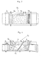
- This circulation tank comprises a circulation passage Bo mounted in a vertical direction on blocks Ao upstanding from the ground.
- This measuring section Eo has transparent observation windows Fo on a bottom wall and right and left lateral walls, respectively.
- the circulation passage Bo further includes rectifying devices and flow rate uniformalizing devices such as corner vanes Go, a punched metal sheet Ho and a honeycomb plate Io arranged at appropriate positions, and a surface flow accelerator Jo mounted at a position immediately upstream of the measuring section Eo, thereby to produce a constant, linear current flowing at a highly uniformalized flow rate through the measuring section Eo.
- the flow rate of the linear current flowing through the measuring section Eo is adjusted as necessary, while retaining its constancy, between a minimum flow rate of about 0.05 m/sec and a maximum flow rate of about 2.0 m/sec by adjusting rotational rate of electromotors Ko for driving the right and left pair of flow rate generating impellers Co.
- Reference Lo denotes foam eliminating devices.
- the measuring section Eo While the measuring section Eo is constantly partitioned at a position upstream thereof by the honeycomb plate Io as described, an extreme downstream portion thereof is normally in an open state and its interior includes nothing except a subject to be tested in a normal situation for carrying out a precision hydromechanical test such as a shipping performace test.
- the measuring section includes an inclined porous plate Mo at an extreme downstream position thereof, which is inclined with an upper portion thereof positioned progressively toward a downstream side, to prevent persons to be positioned-in the measuring section Eo as subjects to be experimented on from being washed away while permitting passage of the water current and also to serve as a back support for the subject persons, as shown in the plan view and vertical section view of Fig. 3 and Fig. 4.
- the measuring section Eo includes a stair No at a lateral side thereof to allow the subject persons to walk up and down, and a stationary bar Qo at an upper forward portion thereof for the subject persons to hold on to directly or for attaching straps Oo for the subject persons to hold on to and belts Po for supporting the waists of the subject persons.
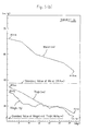
- subject X1, subject X2 and subject X3 Three females were asked to be subjects for experiment (or to be treated persons for trial purposes) (hereinafter referred to as subject X1, subject X2 and subject X3).
- subject X1, subject X2 and subject X3 Three females were asked to be subjects for experiment (or to be treated persons for trial purposes) (hereinafter referred to as subject X1, subject X2 and subject X3).
- subject X1, subject X2 and subject X3 Three females were asked to be subjects for experiment (or to be treated persons for trial purposes) (hereinafter referred to as subject X1, subject X2 and subject X3).
- subjects X1, X2 and X3 Three females were asked to be subjects for experiment (or to be treated persons for trial purposes) (hereinafter referred to as subject X3, but since then further experiments are being conducted also choosing older and more diverent persons as subjects.
- subject X3 is an expert on physical training physiology, and the experiment was conducted such that subject X3 gave instructions to the other subjects X1 and X2 while being experimented on herself.
- a water current controlled to have a predetermined flow rate is generated in the measuring section Eo of the circulation tank corresponding to the treating bath of the present invention, and the three subjects X1, X2 and X3 simultaneously place themselves in the water current in a standing posture or an approximately standing posture in the measuring section Eo.
- Each person is asked to remain facing the upstream side continuously for a predetermined time without being washed away by holding the strap Oo or the stationary bar Qo or using the belt Po secured to the stationary bar Qo to support her waist, or else to lean against the inclined porous plate Mo.
- a training is effected for the predetermined time in which water current massages are applied to the entire body regions of the subjects from the neck down.
- the subjects X1, X2 and X3 leave the treating bath (or the measuring section Eo) to be checked of the health condition such as by blood pressure measurement. Also each of the subjects X1, X2 and X3 is asked how she feels and other matters she noticed, which are recorded.
- the first aspect of the present invention is adapted to provide a method of water current type slimming, beauty and health promotion assuring excellent results in health control (health promotion, increase of physical strength, elimination of mental stress and so forth), rehabilitation of convalescent or physically handicapped persons and various other aspects, not to mention the slimming and beauty treatment which is of primary concern, without causing any excessive burden on the heart or any harmful influence such as a side effect or development of a rough skin, without causing any psychological effect or uneasy feeling.
- Such method is readily available to anyone and yet places very little burden on trainers or instructors, and are also very economical.
- the apparatus according to the second aspect of the present invention having the already described characterizing features, namely the water current type apparatus for slimming, beauty and health promotion adapted exclusively for carrying out the method according to the first aspect of the present invention in a very convenient and desirable manner, has been developed.
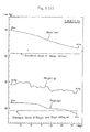
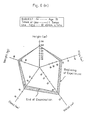
- a further training experiment has been carried out using the water current type apparatus for slimming, beauty and health promotion and selecting people of varied ages and degrees of diverence to be subjects for the experiment. Results obtained from this experiment are shown in the proportion graphs of Fig. 6 (a) - (e). These proportion graphs have been prepared assuming that an ideal proportion is represented by a regular pentagon.
- this method of water current massaging type slimming and beauty treatment may be said to have its most salient characteristics in that, unlike the other, conventional methods which .
- a relatively mild-stimulation in the form of water current massaging is employed (the water current is applied to the layers of fat to cause repeated deformations through the fluttering phenomenon to take off the stiffness of the fat) to arouse the surplus fat discharging function that the living body has by nature and to strengthen that function whereby the fat is discharged by the living body per se.
- Fig. 6 (e) shows results of checking influences where this water current massaging type slimming and beauty training is applied to a person originally having a good proportion. As seen, the training has made her slimmer as a whole but her originally beautiful proportion has not been affected.
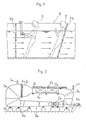
- Fig. 1 is a schematic side view in vertical section of a treating bath for illustrating the basic concept of the method of water current type treatment for slimming, beauty and health promotion according to a first aspect of the present invention
- Fig. 2 is a schematic overall side view, partly in section, of a circulation tank for hydromechanical testing used in a basic experiment for inspecting the functional effect of the method according to the present invention
- Fig. 3 is a plan view of a principal portion in the experimental application
- Fig. 4 is a side view in vertical section of the principal portion in the experimental application
- Fig. 5 (a), (b), (c) show graphs of results of the basic experiment
- Fig. 6 (a), (b), (c), (d), (e) show graphs of results of a further experiment, respectively.
- Fig. 7 to Fig. 32 show varied specific examples of water current type apparatus for slimming, beauty and health promotion according to a second aspect of the present invention.
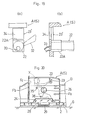
- Fig. 7 is a schematic overall side view in vertical section of a first embodiment.
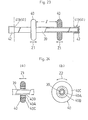
- Fig. 8 to Fig. 29 show a second embodiment and varied modifications and examples of application thereof, in which Fig. 8 is a schematic overall plan view of the second embodiment appratus, Fig. 9 is a sectional view taken on line III-III of Fig. 8, Fig. 10 is a sectional view taken on line IV-IV of Fig. 8, Fig. 11 is a sectional view taken on line V-V of Fig. 8, Fig. 12 is a sectional view taken on line VI-VI of Fig. 8, Fig. 13 is a sectional view taken on line VII-VII of Fig. 8, and Fig. 14 is a sectional view taken on line VIII-VIII of Fig. 8.
- Fig. 8 is a schematic overall plan view of the second embodiment appratus
- Fig. 9 is a sectional view taken on line III-III of Fig. 8
- Fig. 10 is a sectional view taken on line IV-IV of Fig. 8
- Fig. 11 is a sectional view taken on line
- Fig. 15 is an enlarged view in vertical section of a principal portion showing a modification of the second embodiment
- Fig. 16 (a), (b) are a front view and a cross-sectional view of a principal portion showing another modification
- Fig. 17 and Fig. 18 are a perspective view and an enlarged front view, partly in section, of a principal portion showing a further modification
- Fig. 19 (a), (b) are an enlarged front view and an enlarged cross-sectional view of the principal portion showing a still further modification.
- Fig. 20 is a side view in vertical section of a principal portion showing an example of application of the second embodiment
- Fig. 21 (a) is a front view partly in section of a principal portion thereof
- Fig. 21 (b) is a front view, partly in section, of the principal portion showing a modification thereof
- Fig. 22 is a side view in vertical section of the principal portion showing another example of application
- Fig. 23 is an enlarged side view, partly in section, of a principal portion thereof
- Fig. 24 (a), (b) are a side view, partly in section, and a front view, partly in section, of a principal portion showing a modification thereof.
- Fig. 26 show a further example of application wherein the second embodiment is formed into a unit
- Fig. 25 being an overall plan view partly in section
- Fig. 26 being a sectional view taken on line XVIII-XVIII of Fig. 25
- Fig. 27 is an overall plan view partly in section showing an example of application wherein a central control system is provied for a plurality of the above units.
- Fig. 28 is a schematic overall plan view showing a further modification of the second embodiment
- F ig. 29 (a), (b) are a schematic overall plan view and a schematic overall front view showing a further modification of the second embodiment.
- Fig. 30 (a), (b) are a schematic overall plan view and an overall front view partly in section showing a third embodiment.
- Fig.'31 (a), (b), (c) are a schematic overall front view partly in section, a schematic overall side view partly in section, and a schematic overall plan view of a fourth embodiment.
- Fig. 32 is a schematic overall side view partly in section of a fifth embodiment.
- this treating method comprises generation of a water current (horizontal linear current flowing in one direction in this drawing) with a relatively high predetermined flow rate (about 0.6 to 2.0 m/sec) in a treating bath S defined, for example, by porous partition plates Fa, Fb or the like mounted at an upstream position and a downstream position in a portion of a water circulation passage.
- a treated person X is positioned in the water current in the treating bath S in a posture to receive the water current from a direction perpendicular to or approximately perpendicular to her lengthwise direction (a standing posture or approximately a standing posture in this drawing).
- the operation of applying the water current to the treated person X directly and continuously for a predetermined time is effected intermittently (repeatedly) over a predetermined period of time.
- the water current may be a linear current flowing in one direction through the treating bath S as shown in Fig. 1 or may comprise linear shower jet streams flowing in one direction through the treating bath S.
- a circular current may be employed which revolves in the treating bath S about an axis parallel to or approximately parallel to the lengthwise direction of the treated person X.
- the water current may be a linear current flowing in a horizontal direction in the treating bath S in which the treated person is positioned in a standing posture as shown in Fig. 1, or may be a linear current flowing downwardly in the treating bath S in which the treated person X is positioned in a near lying posture as shown in Fig. 31, for example, which will be described later.
- the flow rate of the water current may suitably be adjusted according to the physical strength, health condition, treating time, treating period, fatigue state and so forth of the treated person X.
- the temperature of the water current may suitably be adjusted according to an ambient temperature, and to the physical strength, health condition, treating time, treating period, fatigue state and so forth of the treated person, or may be adjusted in a more positive sense in order to promote perspiration. These adjustments will produce excellent results for slimming, beauty and health promotion, and from the point of view of comfortable training.
- the water current may be mixed with a cosmetic agent or a nutrition promoting agent which assists in developing a beautiful skin, or with a bleaching agent, a germicidal agent, a cleaning agent or the like.
- This apparatus is well suited for use, for example, in a training center, a hospital or the like and permits a relatively large number (4 to 6, for example) of persons X to be treated (or trained) at the same time (or together).
- the apparatus is constructed as shown in Fig. 7.
- the apparatus comprises a circulation passage C mounted in an up and down direction (or vertically) on bases 1 and blocks 2 projecting from a downstairs floor.
- the circulation passage C includes an impeller type water current generating mechanism D inside a lower closed passage portion B.
- the circulation pasage C has an upper horizontal open passage portion A defining a treating bath C having a square cross-section and a relatively large capacity, with a free water surface WS opening upstairs.
- This treating bath S has an extreme upstream end and an extreme downstream end defined by porous partition plates Fa, Fb permitting passage of the water current, respectively.
- the downstream porous partition plate Fb in particular, while acting to prevent the treated persons X from being washed away, is inclined at a suitable angle (normally 10 to 30 degrees, which may be variable) with an upper portion thereof positioned progressively toward a downstream side so as to provide a back support for the treated persons X.
- the treating bath S further includes a stair 6 at a lateral side thereof to allow the treated persons X to walk up and down.
- the stair 6 is provided with rails 7 extending along respective sides thereof to enable also a wheel chair and a platform car to be moved up and down.
- the treating bath S has a skidproof member 5 applied to an inner bottom surface to protect the treated persons X from slipping, and stationary bars 10 above a forward position and an intermediate position of the treating bath S for the treated persons X to hold on to directly, or for attaching straps 8 for the treated persons X to hold on to, and/or for attaching belts 9 for supporting the waists of the treated persons X.
- the treating bath S has transparent observation windows (not shown) in a bottom wall and respective lateral walls, but these windows need not be provided.
- Number 3 in Fig. 7 denotes corner vanes and number 4 denotes a necessary space defined interiorly of the circulation passage C.
- a foamless, constant, linear current must be generated to flow at a highly uniformalized flow rate through a measuring section thereof corresponding to the treating bath S of the present invention. Therefore, it is essential to provide the water circulation tank of this kind with a rectifying device, a flow rate uniformalizing device and a foam eliminating device comprising a punched metal sheet, a honeycomb plate and a surface flow accelerator, and an entire circulation passage inevitably has a complicated configuration. Not only that, the measuring section is allowed a capacity of about 15 to 20% at most with respect to the entire circulation passage.
- the uniformity of flow rate and the foam offer no problem with the apparatus of this invention, and therefore the abovementioned rectifying device, flow rate uniformalizing device and foam eliminating device are omitted from this apparatus, with the entire circulation passage C having a very simple construction, and with the treating bath S having a large capacity of about 40 to 50% with respect to the entire circulation passage C.
- the foam eliminating device may be provided where foam is generated intensively in the circulation passage C.
- Fig. 7 number 11 denotes an electric drive device (a motor and reduction gearing) for driving the impeller type water current generating mechanism D, number 12 denotes a heater with a recirculation pump for heating the water in the circulation passage C, number 13 denotes a city water (normal temperature water) supply pipe with an electromagnetic open/close valve 14, and number 15 denotes an exhaust pipe with an electromagnetic open/close valve 16.
- These electric drive device 11, heater 12 and electromagnetic valves 14, 16 are manually controllable through a controller 17, and also automatically controllable (by feedback control) by the controller 17 in response to water temperature and water level detections input to the controller 17 from a bath water temperature detector 18 and a bath water level detector 19, in order to maintain the water temperature and the water level at set values.
- the flow rate of the linear current flowing in one direction through the treating bath S is adjusted to a selected value, up to about 2.0 m/sec., set to the controller 17, by adjusting a rotational rate of the electric drive device 11 for rotating the impeller type water current generating mechanism D.
- the temperature of the water current flowing through the treating bath S is automatically adjusted to a selected value set to the controller 17, by opening and closing the electromagnetic valve 14 mounted in the city water supply pipe 13, opening and closing the electromagnetic valve 16 mounted in the exhaust pipe 15 or by controlling the heater 12 as necessary.
- the heater 12 is operable in response to a water temperature increasing instruction from the controller 17 to draw the water from the circulation passage C and return the water to the circulation passage C after heating it to a high temperature, and may be the gas combustion type, the electric type or any other type.
- the water level in the treating bath S is automatically adjusted to a selected value set to the controller 17, by opening and closing the electromagnetic valve 14 mounted in the city water supply pipe 13 and opening and closing the electromagnetic valve 1 6 mounted in the exhaust pipe 1 5 as necessary.
- Number 21 in the drawing denotes a hand- operated auxiliary water supply duct.
- Second Embodiment (Medium Size Circular Flow Tank Type Recirculating Water Current Apparatus for Slimming, Beauty and Health Promotion)
- This apparatus permits one person or a relatively small number (2 or 3, for example) of persons to be treated or trained, and has a size to consume a minimum amount of water.
- the apparatus is well suited for use, for example, in a beauty salon or at welfare facilities or health maintenance facilities of a private corporation.
- the apparatus comprises a circulation passage C mounted in a horizontal position on a floor G and a base 1 and blocks 2 arranged on the floor G and defining, in a horizontal open passage portion A, a treating bath S of a size to accommodate one person or a few persons under treatment in a standing posture or approximately a standing posture.
- the apparatus includes an impeller type water current generating mechanism D in a closed passage portion B continuous from upstream and downstream ends of the horizontal open passage portion A, to accelerate water contained in the circulation passage C in one direction.
- the apparatus constitutes a horizontal circulation type circulating water current apparatus for slimming, beauty and health promotion adapted to permit one person to be treated (or trained) alone or a plural number of (two or three) persons to be treated at the same time (or together).
- the circulation pasage C having the horizontal open passage portion A and the closed passage portion B in this example comprises a plurality of blocks formed of FRP and coupled to one another, but may be formed of a steel plate or a polyvinyl chloride plate.
- a boundary portion Ef between the horizontal open passage portion A constituting the treating bath S and the closed passage portion B positioned upstream thereof is shaped to flare in width from an upstream end to a downstream end thereof.
- the closed passage portion B positioned upstream of the horizontal open passage portion A has a minimal width.
- the closed passage portion B disposed upstream of the horizontal open passage portion A has a minimum width, while a width just large enough to include the width occupied by the treated person or persons X and the marginal width for permitting the water to flow smoothly through right and left sides of the treated person or persons X is secured as a maximum width of the horizontal open passage portion A constituting the treating bath S whereby a sufficient amount of water current acts on the treated person or persons X.
- the entire circulation passage C is rendered very compact, and hence requires only a very small amount of water to be circulated, permitting the water current generating mechanism D to be small and the circulation passage C to be manufactured at low cost.: This readily achieves a significant reduction in the manufacturing cost and running cost of the entire apparatus and also'in the installation space for the apparatus.
- the example shown in Fig. 8 has the upstream end of the horizontal open passage portion A flaring progressively in the downstream direction.
- the closed passage portion B disposed upstream of the horizontal open passage portion A may be constructed to include a downstream end flaring progressively in the downstream direction.
- a transitional part from the closed passage portion B to the horizontal open passage portion A may be shaped to grow wider in a stepped manner.
- Fig. 8 number 3 denotes corner vanes, number 11 denotes an electric drive device for driving the impeller type water current generating mechanism D, number 12 denotes a heater with a recirculation pump for heating the water in the circulation passage C, number 13 denotes a city water supply pipe with an electromagnetic open/close valve 14, number 15 denotes an exhaust pipe with an electrcmagnetic open/close valve 16, number 17 denotes a controller 8, number 18 denotes a bath water temperature detector, and number 19 denotes a bath water level detector.
- These elements have the same constructions and functions as those in the preceding
- the horizontal open passage portion A includes porous partition plate Fa, Fb in lattice form at an extreme upstream end and an extreme downstream end thereof to permit passage of the water current.
- the downstream partition plate Fb has fine-mesh net Fc similar to a fishing net spread over a front face thereof.
- this downstream partition plate Fb stands vertically in this example, it may be inclined at a suitable degree (normally 10 to 30 degrees, which may be variable) with an upper portion thereof positioned progressively toward a downstream side so as to provide a back support for the treated person or persons X.
- the horizontal open passage portion A includes a horizontal catch bar member 22 removably attached to a forward position thereof above a water surface for the treated person X to hold on to so as not to be washed away.
- This horizontal catch bar member 22 is formed, for example, of a round steel or stainless steel bar or a round pipe, and is removably supported by a right and left pair of approximately U-shaped supports 23, 23.rigidly attached to and projecting from inner surfaces of right and left lateral walls of the horizontal open passage portion A.
- the horizontal open passage portion A includes lighting windows 24 formed of transparent acryl or glass plates at right and left corners in a bottom thereof, the windows being inclined at about 45 degrees in this example, through which illuminators 25 arranged outside the treating bath S throw light on the treated person X in the treating bath S.
- Videotaping windows 26 formed of transparent acryl or glass plates are mounted in the right and left lateral walls of the horizontal open passage portion A, through which a video camera 27 disposed outside the treating bath S may photograph the treated person X in the treating bath S.
- the lightin windows 24, illuminators 25 and videotaping windows 26 ray be mounted in only one of the lateral walls of the horizontal open passage portion A.
- Such a videotaping system enables the treated person X to become aware of changes in her own figure due to the water current or a trainer (or instructor) to observe conditions of the treated person X with great ease. It is also useful for collecting and storing data.
- the horizontal open passage portion A defines a downwardly projecding recess 28 approximately centrally of its bottom.
- This construction realizes a sufficient depth of water where the treated person or persons X stand(s) and at the same time minimizes the depth of water in the horizontal open passage portion A taken as a whole, which results in a further reduced capacity of the circulation passage C. Consequently, owing also to this aspect the entire circulation passage C is rendered very compact, and hence requires only a very small amount of water to be circulated, permitting the water current generating mechanism D to be small and the circulation passage C to be manufacdured at low cost. This readily achieves a significant reduction in the manufacturing cost and running cost of the entire apparatus.
- the recess 28 also performs a skidproofing function since peripheries thereof provide a foot catch for the treated person X.
- the recess 28 is shown having a circular shape in plan view according to this example, it may have a different shape such as a rectangular shape. As shown in a dot and dash line in Fig. 15, the recess 28 may have a bottom surface inclined such that the surface rises higher toward a forward end thereof. Also, as shown in a double dots and dash line in Fig. 15, the recess 2 may have an inverted trapezoidal sectional shape.
- a turntable 29 is mounted in the recess 28, as shown, to be rotatable on a vertical axis Y to permit the treated person X to make a twisting motion or the like with ease.
- the turntable 29 may be removably mounted in the recess 28, or may be mounted in a constantly fixed manner by means of a fixed ring 30 as shown in Fig. 15. Where the turntable 29 is mounted in a constantly fixed manner as in the latter case, it will be convenient to arrange the turntable 29 switchable by means of an oscillating type stopper 31 or the like between a rotatable state and a locked state.
- the aforesaid projecting U-shaped supports 23 for supporting the horizontal catch bar member 22 for the treated person X to hold on to in order not to be washed away may be replaced by verticaly elongate support recesses 23' defined respectively in inner surfaces of the right and left walls of the horizontal open passage portion A, as shown in Fig. 16 (a), (b).
- the projecting U-shaped supports 23 or support recesses 23' may readily be formed integral when shaping the blocks from FRP.
- the horizontal catch bar member 22 may comprise a pipelike material with, for example, at least opposite ends 22A thereof formed angular so as to be unrotatably supported by the U-shaped supports 23 projecting from the right and left lateral walls of the horizontal open passage portion A.
- the projecting U-shaped supports 23 may be replaced by the vertically elongate support recesses 23' defined respectively in the inner surfaces of the right and left lateral walls of the horizontal open passage portion A.
- the projecting U-shaped supports 23 may be replaced by the vertically elongate support recesses 23' defined respectively in the inner surfaces of the right and left lateral walls of the horizontal open passage portion A.
- Fig. 20 shows a further example of application.
- back support bar members 35, 36 in form of uneven parallel bars are provided in underwater positions in the horizontal open passage portion A for supporting an upper back portion and the buttocks of the treated person X to enable the treated person X to receive the water current in a comfortable posture.
- These back supporting parallel bar members 35, 36 too desirably, are formed of round bars or round pipes from the point of view of the touch felt by the treated person X and resistance characteristics with respect to the water current.
- the horizontal catch bar member 22 may be dispensed with.
- support means for these back supporting parallel bar members 35, 36, projecting support members 37 or support recesses 38 desirably having such a shape as to reliably retain the bar members 35, 36 against the water current are defined by the right and left lateral walls of the horizontal open passage portion A.
- Fig. 22 shows another example of application.
- the treating bath S defined in the horizontal open passage portion A includes a single back supporting horizontal bar member 39 against which the treated person X may lean back.
- the back supporting horizontal bar member 39 carries a pair of spot stimulating projections 40 for pressing against effective spots in the back or nape of the treated person X.
- the inner surfaces of the right and left lateral walls of the treating bath S define mutually opposed bar supporting recesses 41 for receiving and engaging respective ends of the back supporting horizontal bar member 39, and the back supporting horizontal bar member 39 is removably supported by the right and left bar supporting recesses 41, namely removably mounted relative to the treating bath S.
- Each of the right and left bar supporting recesses 41 comprises a bar moving inclined groove 41a with an upper portion thereof positioned progressively rearwardly, and a plurality of bar supporting horizontal grooves 41b branching rearwardly from the bar moving inclined groove 41a, whereby the back supporting horizontal bar member 39 is variable in its vertical position and fore and aft position with respect to the treating bath S.
- the treated person X may set the back supporting horizontal bar member 39 to any selected position at will such as a position suited to stimulate spots in the nape by means of the spot stimulating projections 40, a position suited to stimulate spots in the upper back (lower shoulders), a position suited to stimulate spots in the lower back (waist) or a position suited to stimulate spots in the buttocks.
- the back supporting horizontal bar member 39 is formed of a strong round pipe such as a surface-coated steel pipe and carries caps 42 of rubber or other elastic material covering the opposite engaging ends thereof engageable with the bar supporting recesses 41 (bar supporting horizontal grooves 41b) defined in the inner surfaces of the right and left lateral walls of the treating bath S.
- the pair of spot stimulating projections 40 each comprise a ring element formed of rubber or other elastic material fitted tight on the back supporting horizontal bar member 39.
- the pair of spot stimulating projections 40 comprising elastic ring elements are each fixed in position, in its natural condition, on the back supporting horizontal bar member 39 by a frictional force between an inside face thereof and an outer face of the back supporting horizontal bar member 39, and are forcibly slidable as shown by arrows Z1 in the drawing, to vary transverse positions thereof on the back supporting horizontal bar member 39 and a mutual distance L
- the above arrangement that the pair of the spot stimulating projections 40 are forcibly slidable on the back supporting horizontal bar member 39 to vary the transverse positions and the mutual distance Z , has the advantage that the treated person X can accurately place the spot stimulating projections 40 against desired spots of her body.
- Fig. 24 (a), (b) shows a modified example of the spot stimulating projections 40, wherein the pair of spot stimulating projections 40 are rotatable in directions indicated by an arrow Z2 relative to the back supporting horizontal bar member 39, respectively, in addition to being forcibly slidable in the directions indicated by the arrows Z1 relative to the back supporting horizontal bar member 39 to vary the transverse positions and the distance e between each other on the back supporting horizontal bar member 39 and fixable when in the natural state.
- each of the pair of spot stimulating projections 40 comprises a roller member including a relatively thin elastic ring element 40B fixed to an inside face of a bearing or other rotary element 40A for producing a frictional force and a relatively thick elastic ring element 40C fixed to an outside face of the bearing or other rotary element 40A for spot stimulating purposes.
- the described arrangement in which the pair of spot stimulating projections 40 are rotatable about the back supporting horizontal bar member 39, has the advantage that little or no friction occurs between outer faces of the spot stimulating projections 40 and the skin of the treated person X, thereby to cause no pain for the treated person X.
- the treated person X may select any desired posture suited to herself from a variety of postures, i.e. not only a posture to receive the water current while just holding on to the horizontal catch bar member 22, but also a posture leaning against the back supporting horizontal bar member 39 while holding on to the horizontal catch bar member 22, and a posture just leaning against the back supporting horizontal bar member 39 without holding the horizontal catch bar member 22. Even if the hand should inadvertently lose hold of the horizontal catch bar member 22, the body would be supported by the back supporting horizontal bar member 39 which effectively prevents the treated person from tumbling down washed by the water current, thereby assuring safety.
- the treated person X can enjoy a very comfortable feeling and very effectively eliminate stiffness of the shoulder while receiving water current massages over the entire body and pleasant stimulations at spots in the back or the nape by means of the spot stimulating projections 40 mounted on the back supporting horizontal bar member 39.
- the water current flowing through the treating bath S is generated mainly by the impeller type water current generating mechanism, it includes pulsating flow components of considerably high frequency, by nature. Such a water current produces K arman vortexes around the body of the treated person X, further complicating the pulsating flow components. Therefore, complex stimulations due to the pulsating flow components, and not just a simple pressing force, act through the spot stimulating projections 40 upon the spots in the back or nape of the treated person X receiving the water current massages, which is most desirable in providing good comfort.
- Fig. 25 and Fig. 26 show a unit U including, in a single room in a compact, attractive and decorated manner, the main body portion of the medium size circular flow tank type recirculating water current apparatus for slimming, beauty and health promotion, excluding the mechanical parts such as the electric drive device 11, heater 12, city water supply pipe 13 and exhaust pipe 15.
- Number 43 in the drawings denotes a room frame having a door 44. Only the horizontal open pasage portion A constituting the treating bath S of the main body of the appratus is open, as it is, to an upper portion of the room, the other passage portions being covered by smoothly planed boards.
- number 45 denotes a passage leading to the door 44
- number 46 denotes a forward platform
- number 47 denotes a rearward platform.
- the passage 45 includes a table 49 with a trainer's seat 48 and the controller 17, stools 50 for the treated person herself and her attendants or the like, a changing room 51, a shower and toilet compartment 52 and so forth.
- the forward platform 46 supports a TV set for showing a picture of the interior of the treating bath S taken by the video camera 27 and flower pots and others
- the rearward platform 47 supports an air conditioner 54, flower pots and so forth.
- the unit U may naturally have a minimum floor area necessary for the purpose and a minimum height. It is therefore more suitable for constructing the compact unit U than a vertical circulation type apparatus described later.
- the mechanical parts such as the electric drive device 11, heater 12, city water supply pipe 13 and exhaust pipe 15 may also be disposed in each room frame 43, but these mechanical parts are arranged outside each room frame 43 in this example to facilitate installation and maintenance.
- Fig. 27 shows an example of centralized control system with a plurality of such circulating water current type slimming, beauty and health promotion units U arranged side by side, in which controls of each unit U and instructions for each treated person X are effected from a single controlroom T.
- controlroom T includes a plurality of TV cameras 61 in an arcuate arrangement to output pictures and sound signals transmitted from the video cameras 27 and interphones 61 of the respective units U, and a controller 62 adapted to effect controls of the units U and provide instructions for the treated persons X, respectively.
- the controller and the trainer's seat need not be provided in each unit U, as shown, and also the number of trainers may be cut drastically which assures a great economical merit.
- Fig. 28 shows a further modification of this apparatus according to the second embodiment.
- the boundary Ef between the horizontal open passage portion A constituting the treating bath S and the closed passage portion B disposed upstream thereof is shaped such that its downstream end is wider than its upstream end, but a boundary Ea between the horizontal open passage portion A and the closed passage portion B disposed downstream thereof is shaped such that its downstream end is narrower than its upstream end.
- This construction permits the closed passage portions B disposed upstream and downstream of the horizontal open passage portion A both to have a minimum width.
- the closed passage portions B disposed upstream and downstream of the horizontal open passage portion A have a minimum width, while a width just enough to include a width occupied by the treated person X and a marginal width for permitting the water to flow smoothly through right and left sides of the treated person X is secured as a maximum width of the treating bath whereby a sufficient amount of water current acts on the treated person X.
- the entire circulation passage C is rendered very compact, and hence requires only a very small amount of water to be circulated, permitting the water current generating mechanism D to be small and the circulation passage C to be manufactured at low cost. This readily achieves a significant reduction in the manufacturing cost and running cost of the entire apparatus and also in the installation space for the apparatus. Since the horizontal open passage portion A is constricted at its downstream portion, the water current will readily flow round rearwardly of the treated person X which produces a secondary advantage of assuring an improved water current massaging effect.
- the above example has the upstream end of the horizontal open passage portion A flaring progressively in the downstream direction and the downstream end tapering progressively in the downstream direction.
- the closed passage portion B disposed upstream of the horizontal open passage portion A may be constructed to include a downstream end flaring progressively in the downstream direction, and the closed passage pordion B disposed downstream of the horizontal open passage portion A constructed to include an upstream end tapering progressively in the downstream direction.
- a transitional part from the upstream closed passage portion B to the horizontal open passage portion A may be shaped to grow wider in a stepped manner, and a transitional part from the horizontal open passage portion A to the downstream closed passage portion B shaped to grow narrower in a stepped manner.
- This is a compact and personal type apparatus for only one person to be treated (or trained) and is well suited for use by a household or in a hotel room.
- the apparatus is constructed as shown in Fig. 30 (a), (b).
- a first outstanding feature of this apparatus is that a circulation passage including a treating bath S is constructed without the inside space 4 as in the first embodiment shown in Fig. 7 and in the second embodiment shown in Fig. 8, Fig. 28 and Fig. 29.
- the entire apparatus is defined by a box having a two- part structure to drastically diminish the size of the apparatus as a whole.
- a second outstanding feature is that a bottom portion of the treating bath S over an impeller type water current generating mechanism D is elevated to form a seat 63 for the treated person X. And by making effective use of a large space in a lower passage of the circulation passage resulting from the elevation of the bottom, a relatively large impeller may be employed as the water current generating mechanism D, whereby the appratus although small readily and reliably realizes a water current of sufficient flow rate.
- the treated person X may kneel down holding a hand rail 64 to slim her waist and thighs into good shape or may be seated on the seat 63 to slim mainly her waist into good shape, as shown. Further, although not shown, she may stand holding the hand rail 64 to slim her thighs and calves. into good shape.
- This apparatus has a treating bath S serving also as an ordinary boxlike bathtub installed in a bathroom of a private dwelling house.
- the boxlike bathtub constituting the treating bath S includes an impeller type water current generating mechanism.D in a recess 66 with a mesh cover 65, which recess is defined in a position of a lower side wall displaced to one corner, the water current generating mechanism being rotatable on an axis slanted slightly upwardly.
- the impeller type water current generating mechanism D rotates, an approximately horizontal circular water current is generated in the boxlike bathtub constituting the bath S, that is a circular flow is generated to circulate about an axis extending in a lengthwise direction or an approximately lengthwise direction of the treated person X positioned approximately centrally of the bath S.
- This bath S includes a cylindrical stool 67 upstanding from the center of the bottom thereof for the treated person X to sit on.
- This cylindrical stool 67 also acts to stabilize the horizontal circular current generated by the impeller type water current generating mechanism D.
- this cylindrical stool 67 is not absolutely necessary.
- Number 68 in the drawings denotes a chained plug.
- the treated person X may kneel down holding a hand rail 64 to slim her waist and thighs into good shape or may be seated on the stool 67 to slim mainly her waist into good shape, as shown. Further, although not shown, she may stand holding the hand rail 64 to slim her thighs and calves into good shape.
- the above circular current produces an excellent effect for slimming, beauty and health promotion substantially equal to the effect produced by the linear current flowing in one direction as in the already described various embodiments.
- This circular water current type apparatus also includes a basic structure available for use as a washing machine. Therefore, the apparatus may additionally include devices provided for an ordinary washing machine such as an overflow opening 69 defined in an upper portion of a side wall of the bath S as shown and the impeller type water current generating mechanism D whose rotation is reversible every predetermined time lapse.
- an ordinary washing machine such as an overflow opening 69 defined in an upper portion of a side wall of the bath S as shown and the impeller type water current generating mechanism D whose rotation is reversible every predetermined time lapse.
- the above arrangement permits three apparatuses, i.e.
- a slimming, beauty and health promotion apparatus, a bathing apparatus and a laundry washing apparatus to be combined into a single apparatus which is neither very large nor complicated, which assures a great advantage in terms of economy and installation space and is extremely effective for improvement in the way of living hereafter. It will be even more convenient if the present apparatus is integrally provided with a dehydrator 70 and a dryer 71 as indicated by phantom lines in Fig. 31 (c).
- a heater 12 acts also as a bath furnace or a hot water supplying device.
- This apparatus is adapted to apply a water current to a treated person in form of linear shower jet streams, and is constructed as shown in Fig. 32.
- This construction comprises a treating bath S formed of a box including a header 72 mounted at a top position therein to direct or shoot shower jet water streams downwardly, a reservoir 73 at a bottom position therein for storing the water falling from the header 72, and a a circulation passage C' with a pump D' for feeding under pressure the water in the reservoir 73 to the header 72.
- the box further includes a porous bed 74 at a vertically intermediate position therein, namely between the header 72 above and the reservoir 73 below, to permit the treated person to lie in a horizontal posture or approximately horizontal posture and to permit the shower jet streams falling from the header 72 with the person in that state to pass to the reservoir 73.
- This porcus bed 74 has an upper surface formed of a porous cushion material 74a.
- the shower jet streams are directed or shot downwardly from above, the shower jet streams may be directed horizontally against a standing person under treatment. Further, a mere water current instead of the shower jet streams may be caused to fall.
- the method of water current type treatment for slimming, beauty and health promotion and apparatus therefor are adapted to produce excellent effects in varied applications such as slimming and beauty (or body shaping) treatment, promotion of health not only physically but also mentally, sports training, rehabilitation and so forth.
- the present method and apparatus are very well adapted for use in beauty salons, training centers, hospitals and the like, and also has high utility at health control and welfare facilities of private corporations. Accordingly, the present invention has a very high degree of utility in the fields in which the method and apparatus embodying the present invention are used or manufactured.
Landscapes
- Health & Medical Sciences (AREA)
- Public Health (AREA)
- Physical Education & Sports Medicine (AREA)
- General Health & Medical Sciences (AREA)
- Epidemiology (AREA)
- Pain & Pain Management (AREA)
- Rehabilitation Therapy (AREA)
- Life Sciences & Earth Sciences (AREA)
- Animal Behavior & Ethology (AREA)
- Veterinary Medicine (AREA)
- Devices For Medical Bathing And Washing (AREA)
- Massaging Devices (AREA)
Abstract
Applications Claiming Priority (8)
| Application Number | Priority Date | Filing Date | Title |
|---|---|---|---|
| JP212079/84 | 1984-10-08 | ||
| JP21207984A JPS6190661A (ja) | 1984-10-08 | 1984-10-08 | 水流式痩身美容健康増進療法とその装置 |
| JP5875785U JPS61174928U (fr) | 1985-04-18 | 1985-04-18 | |
| JP58757/85U | 1985-04-18 | ||
| JP8432085A JPS61240958A (ja) | 1985-04-18 | 1985-04-18 | 循環水流式痩身美容健康増進装置 |
| JP84320/85 | 1985-04-18 | ||
| JP12168685U JPS6230826U (fr) | 1985-08-07 | 1985-08-07 | |
| JP121686/85U | 1985-08-07 |
Publications (2)
| Publication Number | Publication Date |
|---|---|
| EP0197156A1 true EP0197156A1 (fr) | 1986-10-15 |
| EP0197156A4 EP0197156A4 (fr) | 1988-08-23 |
Family
ID=27463685
Family Applications (1)
| Application Number | Title | Priority Date | Filing Date |
|---|---|---|---|
| EP19850904877 Withdrawn EP0197156A4 (fr) | 1984-10-08 | 1985-10-03 | Appareil et traitement esthetique et benefique pour la sante utilisant des courants d'eau. |
Country Status (3)
| Country | Link |
|---|---|
| EP (1) | EP0197156A4 (fr) |
| AU (1) | AU4963685A (fr) |
| WO (1) | WO1986002000A1 (fr) |
Cited By (2)
| Publication number | Priority date | Publication date | Assignee | Title |
|---|---|---|---|---|
| EP0405469A1 (fr) * | 1989-06-27 | 1991-01-02 | HAMBURGER WASSERWERKE GmbH | Piscine à contre-courant |
| GR1009526B (el) * | 2018-02-15 | 2019-05-20 | Χρηστος Γεωργιου Παπαγκικας | Εγκατασταση γυμναστικης με παλμικες κινησεις |
Family Cites Families (12)
| Publication number | Priority date | Publication date | Assignee | Title |
|---|---|---|---|---|
| FR318500A (fr) * | 1902-02-07 | 1902-10-17 | Hoeglaner | Baignoire avec dispositifs pour mettre l'eau en mouvement suivant les effets visés par l'emploi des bains |
| FR322154A (fr) * | 1902-06-16 | 1903-01-29 | Bains Et Lavoirs Economiques D | Système d'appareil hydrothérapique pour bains et douches d'eaux minérales médicamenteuses à circulation continue |
| US2237435A (en) * | 1940-12-12 | 1941-04-08 | Floyd W Ille | Therapeutic bath apparatus |
| US2417499A (en) * | 1944-06-28 | 1947-03-18 | Floyd W Ille | Therapeutic bath |
| FR1582017A (fr) * | 1967-12-29 | 1969-09-26 | ||
| JPS5111918Y2 (fr) * | 1971-06-16 | 1976-03-31 | ||
| US4139001A (en) * | 1976-10-08 | 1979-02-13 | Macabee Lloyd C | Hydro-massage and pulsator apparatus |
| JPS53104089U (fr) * | 1977-01-25 | 1978-08-22 | ||
| US4211216A (en) * | 1978-11-07 | 1980-07-08 | Jacuzzi Bros., Incorporated | Whirlpool bath |
| JPS5789752U (fr) * | 1980-11-25 | 1982-06-02 | ||
| JPS57136333U (fr) * | 1981-02-19 | 1982-08-25 | ||
| US4443900A (en) * | 1983-02-03 | 1984-04-24 | Remeyer Willijan P | Hydrotherapy tank |
-
1985
- 1985-10-03 EP EP19850904877 patent/EP0197156A4/fr not_active Withdrawn
- 1985-10-03 WO PCT/JP1985/000549 patent/WO1986002000A1/fr not_active Ceased
- 1985-10-03 AU AU49636/85A patent/AU4963685A/en not_active Abandoned
Cited By (2)
| Publication number | Priority date | Publication date | Assignee | Title |
|---|---|---|---|---|
| EP0405469A1 (fr) * | 1989-06-27 | 1991-01-02 | HAMBURGER WASSERWERKE GmbH | Piscine à contre-courant |
| GR1009526B (el) * | 2018-02-15 | 2019-05-20 | Χρηστος Γεωργιου Παπαγκικας | Εγκατασταση γυμναστικης με παλμικες κινησεις |
Also Published As
| Publication number | Publication date |
|---|---|
| AU4963685A (en) | 1986-04-17 |
| EP0197156A4 (fr) | 1988-08-23 |
| WO1986002000A1 (fr) | 1986-04-10 |
Similar Documents
| Publication | Publication Date | Title |
|---|---|---|
| Pilates et al. | Return to life through contrology | |
| TWI766915B (zh) | 健康增進裝置 | |
| Heilbronn | The use of hatha yoga as a strategy for coping with stress in management development | |
| EP0197156A1 (fr) | Appareil et traitement esthetique et benefique pour la sante utilisant des courants d'eau | |
| Calthrop | Hydrotherapy and physiotherapy: For bath attendants, nurses and biophysical assistants | |
| JPS6190661A (ja) | 水流式痩身美容健康増進療法とその装置 | |
| JP2001299839A (ja) | 歩行訓練装置 | |
| Macfadden | Vitality supreme | |
| CN205831979U (zh) | 一种用于坐姿排便的脚踏装置 | |
| Pilates et al. | Return to life through Contrology | |
| Worby | The everything yoga book: Improve your strength, flexibility, and sense of well-being | |
| RU2860759C1 (ru) | Способ комплексного оздоровления детского организма и устройство для его осуществления | |
| RU2823199C1 (ru) | Способ восстановления опорно-двигательного аппарата человека | |
| Liebers | Relax with yoga | |
| JP2698377B2 (ja) | 水流式体表刺激装置 | |
| WO2012002828A1 (fr) | Vêtement d'entraînement | |
| CN2678639Y (zh) | 摆臂式自助腰背按摩垫 | |
| RU2173973C2 (ru) | Психобиоэнергетический способ профилактики болезней и оздоровления организма человека | |
| US20180168925A1 (en) | Method of medical treatment of a patient under total submergence in water completely surrounding and affecting the patient's organism | |
| JPS61240958A (ja) | 循環水流式痩身美容健康増進装置 | |
| Seth | 24 Comforting the Labor for Women | |
| JPH067706Y2 (ja) | 床可動式循環流水運動プール | |
| DE102012106934B4 (de) | Vorrichtung zur Durchführung gesundheitsfördernder Übungen und deren Verwendung als Trainingsgerät | |
| KR20000009861U (ko) | 다기능 신체 단련기구 | |
| DE202006005755U1 (de) | Vorrichtung zur Gewichtsreduzierung und Hautbildverbesserung von Personen |
Legal Events
| Date | Code | Title | Description |
|---|---|---|---|
| PUAI | Public reference made under article 153(3) epc to a published international application that has entered the european phase |
Free format text: ORIGINAL CODE: 0009012 |
|
| AK | Designated contracting states |
Kind code of ref document: A1 Designated state(s): AT BE CH DE FR GB IT LI LU NL |
|
| RBV | Designated contracting states (corrected) |
Designated state(s): DE FR GB IT NL |
|
| 17P | Request for examination filed |
Effective date: 19860927 |
|
| A4 | Supplementary search report drawn up and despatched |
Effective date: 19880823 |
|
| 17Q | First examination report despatched |
Effective date: 19900606 |
|
| STAA | Information on the status of an ep patent application or granted ep patent |
Free format text: STATUS: THE APPLICATION IS DEEMED TO BE WITHDRAWN |
|
| 18D | Application deemed to be withdrawn |
Effective date: 19910501 |
|
| RIN1 | Information on inventor provided before grant (corrected) |
Inventor name: TAKEHARA, MASAKI Inventor name: KANEDAWARA, JUNKO |