EP0197183A2 - Bassin en forme de segment - Google Patents
Bassin en forme de segment Download PDFInfo
- Publication number
- EP0197183A2 EP0197183A2 EP85108819A EP85108819A EP0197183A2 EP 0197183 A2 EP0197183 A2 EP 0197183A2 EP 85108819 A EP85108819 A EP 85108819A EP 85108819 A EP85108819 A EP 85108819A EP 0197183 A2 EP0197183 A2 EP 0197183A2
- Authority
- EP
- European Patent Office
- Prior art keywords
- tub
- edge
- halves
- trim
- fastening
- Prior art date
- Legal status (The legal status is an assumption and is not a legal conclusion. Google has not performed a legal analysis and makes no representation as to the accuracy of the status listed.)
- Granted
Links
Images


Classifications
-
- A—HUMAN NECESSITIES
- A47—FURNITURE; DOMESTIC ARTICLES OR APPLIANCES; COFFEE MILLS; SPICE MILLS; SUCTION CLEANERS IN GENERAL
- A47K—SANITARY EQUIPMENT; ACCESSORIES THEREFOR, e.g. TOILET ACCESSORIES
- A47K3/00—Baths; Showers; Appurtenances therefor
- A47K3/02—Baths
- A47K3/06—Collapsible baths, e.g. inflatable; Movable baths
-
- A—HUMAN NECESSITIES
- A47—FURNITURE; DOMESTIC ARTICLES OR APPLIANCES; COFFEE MILLS; SPICE MILLS; SUCTION CLEANERS IN GENERAL
- A47K—SANITARY EQUIPMENT; ACCESSORIES THEREFOR, e.g. TOILET ACCESSORIES
- A47K3/00—Baths; Showers; Appurtenances therefor
- A47K3/02—Baths
Definitions
- the invention relates to a segment-shaped trough with at least one curved part, which is supported by four feet and is provided at least in the curved region with a cladding formed from folded sheet metal.
- Tubs of the type mentioned above are usually designed as shower trays, these being arranged in a corner of the room, so that two sides of this tub are at right angles to one another. The ends of these two sides are connected to each other by an arcuate segment. It is known to wall such tubs. For a more rational production, however, it is advantageous, in particular if the fittings installed underneath the tub are to be easily accessible again, to provide the tub with a sheet metal cladding that covers the area below the tub rim to the floor. Such a panel should be easy to assemble and disassemble to facilitate installation.
- the invention has for its object to design a tub of the type mentioned so that it is to be provided with a panel that can be quickly assembled and disassembled without screws and tools.
- a tub according to the invention is thus supported against the floor by four feet, three feet being arranged in the corners of the tubs, while the fourth foot, i.e. the midfoot is located in the area of the curved segment, in the middle of it.
- the cladding consists of two equal halves, each with an inwardly angled edge.
- the cladding elements are fastened exclusively via latching elements, in which either the edges of the cladding or fastening elements inserted in the edges of the cladding are pressed in.
- the halves of the cladding are identical, so that the cladding parts can be interchanged to simplify storage.
- locking grooves are formed in the fastening elements, which interact with corresponding fastening parts, so that the spacing of the panel relative to the tub can be adjusted.
- the both halves of the cladding itself are connected to one another with locking elements, bores in which these locking elements are inserted being arranged in the inwardly angled edges of the cladding.
- These locking elements have on their other side resilient tongues which have a run-up as well as a run-off slope, so that after pressing the spring tongues into the bores of the adjacent latching element, due to the run-off slope, both halves of the cladding are held resiliently against one another.
- This resilient connection on the one hand maintains a tight fit of the cladding against one another and on the other hand gives the possibility of easily dismantling the cladding again. For this purpose, only the two cladding elements have to be pulled apart with increased force, so that the spring tongues jump out of the bores of the adjacent element.
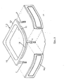
- a tub 1 designed according to the invention is shown in perspective view, which is supported by four feet against the floor, of which the front three feet 2, 3 and 4 are visible.
- the feet 2 and 4 arranged in the corners and the invisible fourth foot are jammed under the edge.
- the attachment of the foot 2 is shown in perspective in FIG. 5.
- the foot 2 has at its lower end a height-adjustable part 5 with which the ground adaptation is carried out.
- This height-adjustable part is attached to an angle iron 6, which in turn is welded to a triangular plate 7.
- the plate 7 is triangular and can be inserted into the corner 8 of the tub 1.
- Plastic wedges 9, 10 are used to connect the foot 2 to the tub 1, which are hammered in between the folded edge 11 of the tub 1 and the plate 7, so that the plate 7 bears against the tub 1 under prestress. There is therefore no need for any screws or other aids to attach the foot.
- the two right-angled sides 12, 13 of the tub 1 are usually arranged directly on a wall, so that only the arcuate part 14 of the tub 1 has to be covered with a panel 15.
- the cladding 15 consists of two identical parts 16, 17, which are connected to the feet 2 - 4 and to one another by means of latching elements which are described in detail below.
- Fig. 3 shows a side view of the foot 2, which is fixed in the corner 6 of the tub 1.
- the height-adjustable part 5 is provided with a threaded bush into which the with a threaded part 18 of the foot is screwed.
- a pincer-shaped clamping element 19 is attached, which can be seen in plan view in Fig. 4.
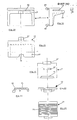
- This clamping element 19 is further shown in FIGS. 10-12 in an enlarged view.
- the clamping element 19 consists of a head part 20 which has a bore 21 through which the height-adjustable part 5 of the foot 2 is pushed.
- a pincer-shaped clamping part 22 is formed on the head part 20, the outside of which is provided with reinforcing ribs 23.
- the opening 24 of the clamping part 22 is narrower than the remaining distance between the pliers 25, 26.
- two cams 27 are formed in the vicinity of the clamping part 22, which form a locking groove 28 between the clamping part 22 and the head part 20 into which the Angle iron 6 of the foot 2 engages so that the pincer-shaped clamping element 19 is fixed in rotation on the foot 2.
- a tongue 29 interacts with the pincer-shaped clamping element 19 and has latching grooves 30 on both sides of its surface.
- the thickness of the tongue 30 increases continuously from its end, the thickness being chosen so that the pliers 25, 26 of the clamping element 19 are pushed apart when inserted and engage in the locking grooves 30 of the tongue.
- the tongue 29 can be fixed in different positions relative to the clamping element 19.
- a knob 31 is formed, which has a greater height than width. This knob 31 is inserted into a bore 32 which is adapted to the shape of the knob. After insertion, the tongue is rotated by 90 ° so that the knob grips behind the panel and thus the tongue 29 is secured against being pulled out is.
- the bore 32 in each cladding 16, 17 lies on a sheet metal part that is angled twice through 90 ° inwards.
- the cladding 17 is fastened to the foot 4 in the same manner as described with the foot 2.
- connection of the two cladding parts 16, 17 with the metatarsus 3 in the lower region takes place via a latching element 33 which is fastened to an angle 34 of the cladding.
- a bracket 36 interacts with the latching element 33, which has latching grooves 35, the end 37 of which is hooked into a pocket 38 formed on the base 3.
- the distance between the cladding 16 and the foot 3 and thus to the tub 1 is achieved by moving the cladding 16 relative to the foot 3, the front end 39 of the bracket 36 engaging in corresponding locking grooves 35 in the locking element 33.
- fastening element 19, 29 as was used for fastening the ends of the trim parts 16, 17 with the feet 2, 4.
- each panel half 16, 17 is fastened with the aid of a fastening element 41 which is fastened to the feet 2-4 by means of latching hooks 42.
- the fastening element 41 has a slot 43 in which the upper, inwardly angled edge 40 of each trim part 16, 17 engages.
- the fastening element 41 is shown in detail in three views in FIGS. 19-21.
- the fastening element 41 has a shoulder 44 on which the edge 40 each cladding element 16, 17 comes to rest, as can be seen from FIG. 7. With the fastening element 41 attached to the midfoot 3, both halves 16, 17 of the lining are fastened.
- a recess 46 is provided in the shoulder 44 for receiving the vertically extending edge 45 of each trim part 16, 17. So that this recess does not have to be made too large, the upper end of the edge 45 is notched, as can be seen from FIG. 7.
- the locking element described above for fastening the lower halves of the trim parts 16, 17 to the metatarsus 3 is shown in more detail in FIGS. 22-25.
- This locking element 33 is clamped in recesses of the angle 34.
- the locking element 33 has lugs 47, 48 and 49, so that no screws are required for fastening the locking element 33 to the angle 34.
- the midfoot 3 is fastened to the tub rim 11 in the same way as described using the foot 2.
- the plate 7 is substantially rectangular, in accordance with the course of the edge 11 of the tub 1.
- a plastic wedge 51 which is between the plate 50 and the inwardly angled part of the Edge 11 is turned.
- an angle 52 is formed, which is supported on an abutment 53 attached to the tub.
- the abutment 53 is L-shaped in side view and thus forms a lateral stop 54 against which the angle 52 of the foot 3 comes to rest.
- this is first inserted into the edge 11 of the tub 1 at a point where there is no abutment 53. Then the foot is moved laterally until the angle 52 abuts the stop 24. Then the plastic wedge 51 is hammered in, so that the metatarsus 3 is held immovably on the tub.
- Spring elements 55 serve to connect the trim parts 16, 17 to one another.
- These spring elements consist of a fastening part 56 which is designed with a rectangular cross section and has an undercut 57 at the upper end. This fastening part is inserted into a bore 58 which is oval. After the fastening part 56 has been inserted into the bore 58, the latter is rotated through 90 °, so that the spring element 55 is held firmly in the bore 58.
- Two spring tongues 60, 61 are formed on the fastening part 56, each of which forms a run-up slope 62 and a run-off slope 63.
- the four feet are first installed and the tub is fitted with the necessary installations. Following this, the two trim parts are connected to one another with the aid of the spring elements, and then the trim with the upper edge 40 is inserted into the slots 43 of the fastening elements 41. At the same time, the tongues 29 are pushed into the pincer-shaped clamping elements and the latching elements 33 are pushed onto the bracket 36. Due to the large number of locking grooves, a fine adjustment of the cladding elements 16, 17 is possible. The assembly of the cladding elements and the feet on the tub 1 is thus carried out without screws or other connecting elements, with all parts such as feet and cladding elements being held together only by a clamping action.
Landscapes
- Health & Medical Sciences (AREA)
- Public Health (AREA)
- Epidemiology (AREA)
- General Health & Medical Sciences (AREA)
- Clamps And Clips (AREA)
- Dowels (AREA)
- Dental Preparations (AREA)
- Pens And Brushes (AREA)
- Connection Of Plates (AREA)
Priority Applications (1)
| Application Number | Priority Date | Filing Date | Title |
|---|---|---|---|
| AT85108819T ATE41296T1 (de) | 1985-03-18 | 1985-07-15 | Segmentfoermige wanne. |
Applications Claiming Priority (2)
| Application Number | Priority Date | Filing Date | Title |
|---|---|---|---|
| DE3509703 | 1985-03-18 | ||
| DE19853509703 DE3509703A1 (de) | 1985-03-18 | 1985-03-18 | Segmentfoermige wanne |
Publications (3)
| Publication Number | Publication Date |
|---|---|
| EP0197183A2 true EP0197183A2 (fr) | 1986-10-15 |
| EP0197183A3 EP0197183A3 (en) | 1987-05-27 |
| EP0197183B1 EP0197183B1 (fr) | 1989-03-15 |
Family
ID=6265565
Family Applications (1)
| Application Number | Title | Priority Date | Filing Date |
|---|---|---|---|
| EP85108819A Expired EP0197183B1 (fr) | 1985-03-18 | 1985-07-15 | Bassin en forme de segment |
Country Status (3)
| Country | Link |
|---|---|
| EP (1) | EP0197183B1 (fr) |
| AT (1) | ATE41296T1 (fr) |
| DE (1) | DE3509703A1 (fr) |
Cited By (5)
| Publication number | Priority date | Publication date | Assignee | Title |
|---|---|---|---|---|
| EP0281957A1 (fr) * | 1987-03-10 | 1988-09-14 | Gebr. Bamberger GmbH & Co. KG | Bassin en forme de segment |
| EP0293676A1 (fr) * | 1987-06-02 | 1988-12-07 | Gebr. Bamberger GmbH & Co. KG | Bassin en forme de segment |
| EP0604899A1 (fr) * | 1992-12-30 | 1994-07-06 | E. Missel GmbH & Co. | Système de support pour baignoire ou cuve de douche |
| WO1997045047A1 (fr) * | 1996-05-29 | 1997-12-04 | Industriverken Plåt & Emalj Ab | Ensemble baignoire, support et procede de montage |
| EP1413236A3 (fr) * | 2002-10-25 | 2005-01-12 | Polypipe Building Products Ltd. | Appareil sanitaire |
Families Citing this family (1)
| Publication number | Priority date | Publication date | Assignee | Title |
|---|---|---|---|---|
| DE3704292C1 (en) * | 1987-02-12 | 1988-02-25 | Kaldewei Franz Gmbh & Co | Corner bathtub with bathtub support |
Family Cites Families (3)
| Publication number | Priority date | Publication date | Assignee | Title |
|---|---|---|---|---|
| FR2161216A5 (fr) * | 1971-11-17 | 1973-07-06 | Odinet Jacques | |
| DE2825146C2 (de) * | 1978-06-08 | 1982-07-08 | Gebr. Bamberger Gmbh U. Co Kg, 3561 Friedensdorf | Bade- bzw. Brausewanne |
| GB2117859B (en) * | 1982-03-31 | 1986-02-19 | Robert Sneddon | Expanding fasteners for bath handles |
-
1985
- 1985-03-18 DE DE19853509703 patent/DE3509703A1/de active Granted
- 1985-07-15 AT AT85108819T patent/ATE41296T1/de active
- 1985-07-15 EP EP85108819A patent/EP0197183B1/fr not_active Expired
Cited By (5)
| Publication number | Priority date | Publication date | Assignee | Title |
|---|---|---|---|---|
| EP0281957A1 (fr) * | 1987-03-10 | 1988-09-14 | Gebr. Bamberger GmbH & Co. KG | Bassin en forme de segment |
| EP0293676A1 (fr) * | 1987-06-02 | 1988-12-07 | Gebr. Bamberger GmbH & Co. KG | Bassin en forme de segment |
| EP0604899A1 (fr) * | 1992-12-30 | 1994-07-06 | E. Missel GmbH & Co. | Système de support pour baignoire ou cuve de douche |
| WO1997045047A1 (fr) * | 1996-05-29 | 1997-12-04 | Industriverken Plåt & Emalj Ab | Ensemble baignoire, support et procede de montage |
| EP1413236A3 (fr) * | 2002-10-25 | 2005-01-12 | Polypipe Building Products Ltd. | Appareil sanitaire |
Also Published As
| Publication number | Publication date |
|---|---|
| DE3509703A1 (de) | 1986-09-18 |
| EP0197183B1 (fr) | 1989-03-15 |
| EP0197183A3 (en) | 1987-05-27 |
| DE3509703C2 (fr) | 1989-07-13 |
| ATE41296T1 (de) | 1989-04-15 |
Similar Documents
| Publication | Publication Date | Title |
|---|---|---|
| DE3632442A1 (de) | Beschlag fuer die verstellbare halterung der laufschiene einer schubladen-ausziehfuehrung | |
| DE2911094A1 (de) | Plattenverbindungssystem | |
| DE10107864A1 (de) | Halteelement für Abdeckleisten | |
| DE102007042250A1 (de) | Einrichtung zur Verbindung und Verriegelung zweier Bauplatten, insbesondere Fussbodenpaneele | |
| EP0802287B1 (fr) | Grille de drainage réglable en hauteur | |
| DE69119037T2 (de) | Wandaufbau, mit Wandbestandteilen befestigt an einen Rahmen mittels nicht-sichtbaren Verbindungen | |
| EP0197183B1 (fr) | Bassin en forme de segment | |
| DE2625202B2 (de) | Haushaltgerät z.B. Geschirrspülmaschine mit einem frontseitigen Sockelrücksprung | |
| EP0387494A2 (fr) | Tiroir de soubassement | |
| DE19506023C2 (de) | Traganker für Fassadenplatten | |
| EP4166054A1 (fr) | Support de baignoire | |
| DE3203804A1 (de) | Stellwaende und verbindungselement fuer stellwaende | |
| DE3641967C2 (fr) | ||
| DE29516040U1 (de) | Tragstütze sowie Tragvorrichtung mit wenigstens vier im Abstand zueinander angeordneten Tragstützen | |
| AT387316B (de) | Aus mehreren teilen zusammensetzbare schublade | |
| DE9416530U1 (de) | Einrichtung zum Abstützen einer Arbeitsplatte an einer Wand o.dgl. | |
| DE2759349C2 (de) | Schublade aus Kunststoff | |
| DE3509458C1 (de) | Bade- oder Brausewannenträger | |
| DE202018105849U1 (de) | Schnallenaufbau zum Montieren einer Speicher-Leiterplatte | |
| DE102004023492A1 (de) | Sockelsystem | |
| WO2024236337A1 (fr) | Système de plinthe, et meuble le comprenant | |
| DE29509556U1 (de) | Schaltschrank mit Montageplatte | |
| DE19931038C2 (de) | Verkleidungssystem für eine Wanne, vorzugsweise Badewanne | |
| DE3803755C2 (fr) | ||
| DE2825146A1 (de) | Bade- bzw. brausewanne |
Legal Events
| Date | Code | Title | Description |
|---|---|---|---|
| PUAI | Public reference made under article 153(3) epc to a published international application that has entered the european phase |
Free format text: ORIGINAL CODE: 0009012 |
|
| AK | Designated contracting states |
Kind code of ref document: A2 Designated state(s): AT BE CH FR IT LI NL |
|
| PUAL | Search report despatched |
Free format text: ORIGINAL CODE: 0009013 |
|
| AK | Designated contracting states |
Kind code of ref document: A3 Designated state(s): AT BE CH FR IT LI NL |
|
| 17P | Request for examination filed |
Effective date: 19871120 |
|
| 17Q | First examination report despatched |
Effective date: 19880728 |
|
| GRAA | (expected) grant |
Free format text: ORIGINAL CODE: 0009210 |
|
| AK | Designated contracting states |
Kind code of ref document: B1 Designated state(s): AT BE CH FR IT LI NL |
|
| REF | Corresponds to: |
Ref document number: 41296 Country of ref document: AT Date of ref document: 19890415 Kind code of ref document: T |
|
| ITF | It: translation for a ep patent filed | ||
| ET | Fr: translation filed | ||
| PLBE | No opposition filed within time limit |
Free format text: ORIGINAL CODE: 0009261 |
|
| STAA | Information on the status of an ep patent application or granted ep patent |
Free format text: STATUS: NO OPPOSITION FILED WITHIN TIME LIMIT |
|
| 26N | No opposition filed | ||
| ITTA | It: last paid annual fee | ||
| PGFP | Annual fee paid to national office [announced via postgrant information from national office to epo] |
Ref country code: CH Payment date: 19920630 Year of fee payment: 8 |
|
| PGFP | Annual fee paid to national office [announced via postgrant information from national office to epo] |
Ref country code: BE Payment date: 19920703 Year of fee payment: 8 |
|
| PGFP | Annual fee paid to national office [announced via postgrant information from national office to epo] |
Ref country code: AT Payment date: 19920727 Year of fee payment: 8 |
|
| PGFP | Annual fee paid to national office [announced via postgrant information from national office to epo] |
Ref country code: FR Payment date: 19920729 Year of fee payment: 8 |
|
| PGFP | Annual fee paid to national office [announced via postgrant information from national office to epo] |
Ref country code: NL Payment date: 19920731 Year of fee payment: 8 |
|
| PG25 | Lapsed in a contracting state [announced via postgrant information from national office to epo] |
Ref country code: AT Effective date: 19930715 |
|
| PG25 | Lapsed in a contracting state [announced via postgrant information from national office to epo] |
Ref country code: LI Effective date: 19930731 Ref country code: CH Effective date: 19930731 Ref country code: BE Effective date: 19930731 |
|
| BERE | Be: lapsed |
Owner name: GEBR. BAMBERGER G.M.B.H. & CO. K.G. Effective date: 19930731 |
|
| PG25 | Lapsed in a contracting state [announced via postgrant information from national office to epo] |
Ref country code: NL Effective date: 19940201 |
|
| NLV4 | Nl: lapsed or anulled due to non-payment of the annual fee | ||
| PG25 | Lapsed in a contracting state [announced via postgrant information from national office to epo] |
Ref country code: FR Effective date: 19940331 |
|
| REG | Reference to a national code |
Ref country code: CH Ref legal event code: PL |
|
| REG | Reference to a national code |
Ref country code: FR Ref legal event code: ST |