EP0197231A1 - Dispositif pour l'emmagasinage de matériel filiforme pour l'insertion de trame d'un métier à tisser - Google Patents
Dispositif pour l'emmagasinage de matériel filiforme pour l'insertion de trame d'un métier à tisser Download PDFInfo
- Publication number
- EP0197231A1 EP0197231A1 EP85810150A EP85810150A EP0197231A1 EP 0197231 A1 EP0197231 A1 EP 0197231A1 EP 85810150 A EP85810150 A EP 85810150A EP 85810150 A EP85810150 A EP 85810150A EP 0197231 A1 EP0197231 A1 EP 0197231A1
- Authority
- EP
- European Patent Office
- Prior art keywords
- disc
- support
- disk
- thread
- nozzle
- Prior art date
- Legal status (The legal status is an assumption and is not a legal conclusion. Google has not performed a legal analysis and makes no representation as to the accuracy of the status listed.)
- Granted
Links
- 239000000463 material Substances 0.000 title claims abstract description 17
- 238000003780 insertion Methods 0.000 title claims description 7
- 230000037431 insertion Effects 0.000 title claims description 7
- 238000009941 weaving Methods 0.000 claims abstract description 10
- 239000004744 fabric Substances 0.000 description 3
- 230000006835 compression Effects 0.000 description 1
- 238000007906 compression Methods 0.000 description 1
- 230000000694 effects Effects 0.000 description 1
- 238000000034 method Methods 0.000 description 1
Images

Classifications
-
- D—TEXTILES; PAPER
- D03—WEAVING
- D03D—WOVEN FABRICS; METHODS OF WEAVING; LOOMS
- D03D47/00—Looms in which bulk supply of weft does not pass through shed, e.g. shuttleless looms, gripper shuttle looms, dummy shuttle looms
- D03D47/34—Handling the weft between bulk storage and weft-inserting means
- D03D47/36—Measuring and cutting the weft
- D03D47/361—Drum-type weft feeding devices
-
- B—PERFORMING OPERATIONS; TRANSPORTING
- B65—CONVEYING; PACKING; STORING; HANDLING THIN OR FILAMENTARY MATERIAL
- B65H—HANDLING THIN OR FILAMENTARY MATERIAL, e.g. SHEETS, WEBS, CABLES
- B65H51/00—Forwarding filamentary material
- B65H51/20—Devices for temporarily storing filamentary material during forwarding, e.g. for buffer storage
-
- D—TEXTILES; PAPER
- D03—WEAVING
- D03D—WOVEN FABRICS; METHODS OF WEAVING; LOOMS
- D03D47/00—Looms in which bulk supply of weft does not pass through shed, e.g. shuttleless looms, gripper shuttle looms, dummy shuttle looms
- D03D47/34—Handling the weft between bulk storage and weft-inserting means
- D03D47/36—Measuring and cutting the weft
-
- B—PERFORMING OPERATIONS; TRANSPORTING
- B65—CONVEYING; PACKING; STORING; HANDLING THIN OR FILAMENTARY MATERIAL
- B65H—HANDLING THIN OR FILAMENTARY MATERIAL, e.g. SHEETS, WEBS, CABLES
- B65H2701/00—Handled material; Storage means
- B65H2701/30—Handled filamentary material
- B65H2701/31—Textiles threads or artificial strands of filaments
Definitions
- the invention relates to a device for storing thread-like material for weft insertion in weaving machines, with a rotating disk carrying the material and a nozzle directed thereon for supplying air and material.
- yarn is assumed as the thread-like material.
- the yarn to be stored is deposited on it in a loop shape by a feed nozzle which is moved back and forth transversely to the direction of rotation of the disk. After being stored, the yarn is drawn off the support disk essentially perpendicular to the surface thereof. The yarn should only be held on the supporting disc by the force of the feed nozzle.
- the loop-shaped yarn deposit can easily become disordered, so that individual loops can overlap.
- the withdrawal of the stored yarn can be disturbed because often multiple loops lying one above the other can be removed at the same time instead of one after the other.
- the embodiment cannot exactly define the beginning and end of the thread length to be stored on the supporting disk; the storage length can therefore only be adapted approximately to the entry length required in the weaving machine.
- the object of the invention is to create a storage device which is particularly improved in this regard.
- the device according to the invention lies in at least one single thread clamp which rotates with the disk, can be moved against it and presses the material onto it.
- a particularly precise point in time for the beginning of a length of storage on the support disk can be defined by the thread clamp. Furthermore, a precise point in time for the end of the storage length and at the same time for the beginning of the weft insertion and thus the withdrawal of the stored thread deposit can also be defined.
- the device is therefore particularly suitable for air jet looms in which the entry length is to be determined by the length of the storage on the weft storage device.
- the weaving machine 1 has two cheeks 2, 3, a warp beam 4, shafts 5 and a fabric beam 6.
- the fabric 7 runs according to arrow 8 from the warp beam 4 through the shafts 5 to the fabric beam 6.
- the weft yarn 11 is guided by means of a main nozzle 12 arranged on the weft side 71 through the shed formed by the shafts 5 to a suction nozzle 13 arranged on the catch side 72.
- a frame 15 is attached to the machine cheek 2.
- a shaft 16 which is vertical in FIG. 2 and is continuously driven by the main drive of the weaving machine 1 during operation, is mounted in it.
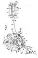
- a support disk 17 for the weft yarn 11 to be stored is fastened on it.
- the shaft 16 and the disk 17 are driven via a toothed belt wheel 18 and a gear 19.
- the support disk 17 is recessed in its inner region 21, while it has an elevation 22 (FIG. 2) in an outer region.
- the disk 17 carries an annular disk-shaped needle felt 23. Its inner area 24 lies in the depression area 21, while the outer area 25 is held in an oblique position relative to the disk 17.
- a cover plate 26 is arranged.
- the felt 23 is held down by it and in particular its inner part 21 is pressed down.
- the outer region 25 is more or less held in the inclined position according to FIG. 2 by the elevation 22.
- a hub 27 of the thrust washer 26 e.g. three arms 81-83 pivotable about pivot bearings 28, on each of which a clamp 31, 32, 33 provided with compression springs 29 is mounted.
- Each spring 29 strives to push the associated clamp 31-33 downward in FIG. 2.
- three tension springs 75 - 77 act on the arms 81-83.
- the terminals 31 - 33 rotate during operation together with the parts 17, 23, 26 according to arrow 34.
- a cam disk 37 arranged above it in FIG. 2 and equipped with a cam 36 stands still during operation.
- Rollers 38 arranged on the arms 81-83 run during operation on the lower surface of the cam disk 37 in FIG.
- a roller 38 runs over the cam 36, e.g. the arm 82 is pivoted downward in FIG. 2 so that the associated clamp 32 reaches the lower clamp position 32a.
- this clamp 32 presses on the pane 17 while passing through the associated cutout 84 provided in the felt 23 at the clamps. This allows a piece of thread 51 of the weft thread 11 blown in by a stationary nozzle 41 to be held on the pane 17.
- the weft yarn 11 is drawn off from a metering drum, not shown.
- the nozzle 41 is protected by a wedge 42 which is arranged in front of the nozzle 41 in the direction of rotation of the support disk 17 (arrow 34).
- the outer area 25 of the felt disk 23 is raised shortly before the inflation point 92 by the wedge 42, so that the ge drew piece of thread 51 comes to lie on the support plate 17. After placing the thread on disk 17, the felt area 23 can fold down more or less of its own accord, so that the thread piece 51 can be easily held from above.
- the mode of action is as follows.
- the disk 17, the felt 23 and the clamps 31 - 33 continuously rotate according to arrow 34.
- An air stream continuously blows from nozzle 41, through which weft thread 11 is continuously deposited on disk 17 in the form of a loop-shaped thread deposit 51.
- Terminal 33 passes through the position shown in Fig. 1. It then runs past the wedge 42 in FIG. 2 and reaches the position 33a. In this, the clamp is pivoted downward as a result of the associated roller 38 running onto the cam 36 in FIG. 2. The end of the stored piece of thread 51 is thereby clamped.
- terminal 33 While terminal 33 is running from position 33 to position 33a, terminal 32 is running from position 32a to position 32b.
- the associated roller 38 leaves the cam 36 under the action of the adjacent springs 75, 77.
- the stored piece of thread 51 of certain length is released.
- the main nozzle 12 receives pressure, the weft insertion begins.
- the support disk 17 continues to run, the stored, precisely defined thread length 51 is drawn off.
- a next thread supply of the same length is deposited between terminals 33 and 31.
- the outer region 25 of the felt 23 is wedged in the sector 61 between two successive clamps 32, 33 during the storage or entry process 42 and the jet from nozzle 41 more or less held in the upper inclined position (corresponding to Fig. 2 left).
- a slight braking effect on the weft thread 51 located under the felt area 25 can optionally take place. This allows it to be kept taut during the entry.
- the cam disk 37 can be pivoted and fixed into a desired position by means of screws 93, 94 and an elongated hole 63.
- the weft storage device can also be used in a weaving machine type other than an air jet machine.
- the entire storage device 51 is initially consumed during one and the same weft insertion and, in addition, a short piece of thread is drawn directly from the nozzle 41.
Landscapes
- Engineering & Computer Science (AREA)
- Textile Engineering (AREA)
- Looms (AREA)
Priority Applications (7)
| Application Number | Priority Date | Filing Date | Title |
|---|---|---|---|
| DE8585810150T DE3563729D1 (en) | 1985-04-02 | 1985-04-02 | Device for storing thread material for the weft insertion into looms |
| EP19850810150 EP0197231B1 (fr) | 1985-04-02 | 1985-04-02 | Dispositif pour l'emmagasinage de matériel filiforme pour l'insertion de trame d'un métier à tisser |
| SU864027181A SU1382405A3 (ru) | 1985-04-02 | 1986-03-27 | Устройство дл накоплени нитевидного материала дл прокладки утка на ткацком станке |
| IN257/CAL/86A IN166326B (fr) | 1985-04-02 | 1986-03-31 | |
| JP7265086A JPS61231239A (ja) | 1985-04-02 | 1986-04-01 | 織機におけるヨコ入れのための繊維状材料を貯蔵するための装置 |
| CS862232A CS264125B2 (en) | 1985-04-02 | 1986-04-01 | Device for weft accumulation for weft loading on weaving machines |
| BR8601441A BR8601441A (pt) | 1985-04-02 | 1986-04-01 | Conjunto para o armazenamento de material filamentoso para a introducao da trama em teares |
Applications Claiming Priority (1)
| Application Number | Priority Date | Filing Date | Title |
|---|---|---|---|
| EP19850810150 EP0197231B1 (fr) | 1985-04-02 | 1985-04-02 | Dispositif pour l'emmagasinage de matériel filiforme pour l'insertion de trame d'un métier à tisser |
Publications (2)
| Publication Number | Publication Date |
|---|---|
| EP0197231A1 true EP0197231A1 (fr) | 1986-10-15 |
| EP0197231B1 EP0197231B1 (fr) | 1988-07-13 |
Family
ID=8194637
Family Applications (1)
| Application Number | Title | Priority Date | Filing Date |
|---|---|---|---|
| EP19850810150 Expired EP0197231B1 (fr) | 1985-04-02 | 1985-04-02 | Dispositif pour l'emmagasinage de matériel filiforme pour l'insertion de trame d'un métier à tisser |
Country Status (7)
| Country | Link |
|---|---|
| EP (1) | EP0197231B1 (fr) |
| JP (1) | JPS61231239A (fr) |
| BR (1) | BR8601441A (fr) |
| CS (1) | CS264125B2 (fr) |
| DE (1) | DE3563729D1 (fr) |
| IN (1) | IN166326B (fr) |
| SU (1) | SU1382405A3 (fr) |
Citations (2)
| Publication number | Priority date | Publication date | Assignee | Title |
|---|---|---|---|---|
| DE1099974B (de) * | 1956-12-15 | 1961-02-23 | Delore Sa Geoffroy | Vorrichtung zum voruebergehenden Speichern von Draht |
| DE2215003A1 (de) * | 1972-03-28 | 1973-10-11 | Karl Bous | Vorrichtung zur garnvorbereitung und -behandlung sowie deren anwendungen |
-
1985
- 1985-04-02 EP EP19850810150 patent/EP0197231B1/fr not_active Expired
- 1985-04-02 DE DE8585810150T patent/DE3563729D1/de not_active Expired
-
1986
- 1986-03-27 SU SU864027181A patent/SU1382405A3/ru active
- 1986-03-31 IN IN257/CAL/86A patent/IN166326B/en unknown
- 1986-04-01 JP JP7265086A patent/JPS61231239A/ja active Pending
- 1986-04-01 BR BR8601441A patent/BR8601441A/pt unknown
- 1986-04-01 CS CS862232A patent/CS264125B2/cs unknown
Patent Citations (3)
| Publication number | Priority date | Publication date | Assignee | Title |
|---|---|---|---|---|
| DE1099974B (de) * | 1956-12-15 | 1961-02-23 | Delore Sa Geoffroy | Vorrichtung zum voruebergehenden Speichern von Draht |
| DE2215003A1 (de) * | 1972-03-28 | 1973-10-11 | Karl Bous | Vorrichtung zur garnvorbereitung und -behandlung sowie deren anwendungen |
| DE2239561A1 (de) * | 1972-03-28 | 1974-02-21 | Karl Bous | Vorrichtung zur garnvorbereitung und -behandlung sowie deren anwendungen |
Also Published As
| Publication number | Publication date |
|---|---|
| IN166326B (fr) | 1990-04-14 |
| CS264125B2 (en) | 1989-06-13 |
| SU1382405A3 (ru) | 1988-03-15 |
| JPS61231239A (ja) | 1986-10-15 |
| EP0197231B1 (fr) | 1988-07-13 |
| BR8601441A (pt) | 1986-12-09 |
| CS223286A2 (en) | 1988-09-16 |
| DE3563729D1 (en) | 1988-08-18 |
Similar Documents
| Publication | Publication Date | Title |
|---|---|---|
| CH636653A5 (de) | Fadenspannvorrichtung an einem spulengatter. | |
| DE3116399C2 (fr) | ||
| CH618400A5 (fr) | ||
| DE2361978A1 (de) | Verfahren und vorrichtung zum andrehen von garnenden an einer offen-end-spinnmaschine | |
| EP0197231B1 (fr) | Dispositif pour l'emmagasinage de matériel filiforme pour l'insertion de trame d'un métier à tisser | |
| CH381622A (de) | Webmaschine | |
| DE2637120C2 (de) | Fadenliefervorrichtung für Textilmaschinen | |
| DE1785574B2 (de) | Vorrichtung zum automatischen rueckspeisen eines fadenendes in die spinnturbine einer offen-end-spinnvorrichtung | |
| DE2743701C2 (de) | Gesteuerte Fadenklemme einer Düsenwebmaschine | |
| DE3207375C2 (de) | Vorrichtung zum Aufwickeln von Fäden | |
| EP0020796B1 (fr) | Dispositif d'alimentation en fil de tour pour métier à tisser | |
| DE1710162C3 (fr) | ||
| DE2621014B1 (de) | Fadenliefervorrichtung fuer Textilmaschinen | |
| DE180445C (fr) | ||
| AT232934B (de) | Webmaschine | |
| CH315292A (de) | Einrichtung zum Entfernen der Fadenreste von Spulen | |
| DE2355065C3 (de) | Läuferbremse für Ringzwirn- oder Ringspinnmaschinen | |
| DE1068190B (fr) | ||
| DE487428C (de) | Spulentraeger fuer Rundflechtmaschinen mit einer staendig auf den Faden einwirkenden, von Hand einstellbaren Fadenbremse | |
| DE2727604A1 (de) | Positive fadenliefervorrichtung, insbesondere fuer rundstrickmaschinen | |
| DE104014C (fr) | ||
| DE2433226C2 (de) | Fadenwächter für Spinn- oder Zwirnspindeln, insbesondere Doppeldrahtzwirnspindeln | |
| DE231799C (fr) | ||
| DE53226C (de) | Differential-Fleyer | |
| DE895728C (de) | Schussfadentrag- und Antriebsvorrichtung fuer Rundwebstuehle |
Legal Events
| Date | Code | Title | Description |
|---|---|---|---|
| PUAI | Public reference made under article 153(3) epc to a published international application that has entered the european phase |
Free format text: ORIGINAL CODE: 0009012 |
|
| 17P | Request for examination filed |
Effective date: 19850406 |
|
| AK | Designated contracting states |
Kind code of ref document: A1 Designated state(s): AT BE CH DE FR GB IT LI LU NL SE |
|
| RBV | Designated contracting states (corrected) |
Designated state(s): BE CH DE FR GB IT LI |
|
| 17Q | First examination report despatched |
Effective date: 19870714 |
|
| ITF | It: translation for a ep patent filed | ||
| GRAA | (expected) grant |
Free format text: ORIGINAL CODE: 0009210 |
|
| AK | Designated contracting states |
Kind code of ref document: B1 Designated state(s): BE CH DE FR GB IT LI |
|
| GBT | Gb: translation of ep patent filed (gb section 77(6)(a)/1977) | ||
| REF | Corresponds to: |
Ref document number: 3563729 Country of ref document: DE Date of ref document: 19880818 |
|
| ET | Fr: translation filed | ||
| PGFP | Annual fee paid to national office [announced via postgrant information from national office to epo] |
Ref country code: GB Payment date: 19890331 Year of fee payment: 5 |
|
| PGFP | Annual fee paid to national office [announced via postgrant information from national office to epo] |
Ref country code: BE Payment date: 19890428 Year of fee payment: 5 |
|
| ITTA | It: last paid annual fee | ||
| PG25 | Lapsed in a contracting state [announced via postgrant information from national office to epo] |
Ref country code: LI Effective date: 19890430 Ref country code: CH Effective date: 19890430 |
|
| PGFP | Annual fee paid to national office [announced via postgrant information from national office to epo] |
Ref country code: DE Payment date: 19890502 Year of fee payment: 5 |
|
| PLBE | No opposition filed within time limit |
Free format text: ORIGINAL CODE: 0009261 |
|
| STAA | Information on the status of an ep patent application or granted ep patent |
Free format text: STATUS: NO OPPOSITION FILED WITHIN TIME LIMIT |
|
| 26N | No opposition filed | ||
| REG | Reference to a national code |
Ref country code: CH Ref legal event code: PL |
|
| PG25 | Lapsed in a contracting state [announced via postgrant information from national office to epo] |
Ref country code: GB Effective date: 19900402 |
|
| PG25 | Lapsed in a contracting state [announced via postgrant information from national office to epo] |
Ref country code: BE Effective date: 19900430 |
|
| PGFP | Annual fee paid to national office [announced via postgrant information from national office to epo] |
Ref country code: FR Payment date: 19901030 Year of fee payment: 6 |
|
| BERE | Be: lapsed |
Owner name: GEBRUDER SULZER A.G. Effective date: 19900430 |
|
| GBPC | Gb: european patent ceased through non-payment of renewal fee | ||
| PG25 | Lapsed in a contracting state [announced via postgrant information from national office to epo] |
Ref country code: DE Effective date: 19910101 |
|
| PG25 | Lapsed in a contracting state [announced via postgrant information from national office to epo] |
Ref country code: FR Effective date: 19911230 |
|
| REG | Reference to a national code |
Ref country code: FR Ref legal event code: ST |