EP0197314A1 - Dispositif hydraulique pour la sélection et la transmission d'un signal de pression dans une soupape directionnelle assemblée par blocs - Google Patents
Dispositif hydraulique pour la sélection et la transmission d'un signal de pression dans une soupape directionnelle assemblée par blocs Download PDFInfo
- Publication number
- EP0197314A1 EP0197314A1 EP86103078A EP86103078A EP0197314A1 EP 0197314 A1 EP0197314 A1 EP 0197314A1 EP 86103078 A EP86103078 A EP 86103078A EP 86103078 A EP86103078 A EP 86103078A EP 0197314 A1 EP0197314 A1 EP 0197314A1
- Authority
- EP
- European Patent Office
- Prior art keywords
- insert body
- recess
- housing
- valve
- hydraulic device
- Prior art date
- Legal status (The legal status is an assumption and is not a legal conclusion. Google has not performed a legal analysis and makes no representation as to the accuracy of the status listed.)
- Granted
Links
- 238000007789 sealing Methods 0.000 claims description 29
- 239000011324 bead Substances 0.000 claims 6
- 241000972773 Aulopiformes Species 0.000 claims 1
- 238000010079 rubber tapping Methods 0.000 claims 1
- 235000019515 salmon Nutrition 0.000 claims 1
- 238000010276 construction Methods 0.000 description 3
- 238000003754 machining Methods 0.000 description 3
- 150000001875 compounds Chemical class 0.000 description 1
- 238000011161 development Methods 0.000 description 1
- 230000018109 developmental process Effects 0.000 description 1
- 238000006073 displacement reaction Methods 0.000 description 1
- 238000004519 manufacturing process Methods 0.000 description 1
- 230000000717 retained effect Effects 0.000 description 1
Images
Classifications
-
- F—MECHANICAL ENGINEERING; LIGHTING; HEATING; WEAPONS; BLASTING
- F15—FLUID-PRESSURE ACTUATORS; HYDRAULICS OR PNEUMATICS IN GENERAL
- F15B—SYSTEMS ACTING BY MEANS OF FLUIDS IN GENERAL; FLUID-PRESSURE ACTUATORS, e.g. SERVOMOTORS; DETAILS OF FLUID-PRESSURE SYSTEMS, NOT OTHERWISE PROVIDED FOR
- F15B13/00—Details of servomotor systems ; Valves for servomotor systems
- F15B13/02—Fluid distribution or supply devices characterised by their adaptation to the control of servomotors
- F15B13/04—Fluid distribution or supply devices characterised by their adaptation to the control of servomotors for use with a single servomotor
- F15B13/0416—Fluid distribution or supply devices characterised by their adaptation to the control of servomotors for use with a single servomotor with means or adapted for load sensing
- F15B13/0417—Load sensing elements; Internal fluid connections therefor; Anti-saturation or pressure-compensation valves
-
- F—MECHANICAL ENGINEERING; LIGHTING; HEATING; WEAPONS; BLASTING
- F15—FLUID-PRESSURE ACTUATORS; HYDRAULICS OR PNEUMATICS IN GENERAL
- F15B—SYSTEMS ACTING BY MEANS OF FLUIDS IN GENERAL; FLUID-PRESSURE ACTUATORS, e.g. SERVOMOTORS; DETAILS OF FLUID-PRESSURE SYSTEMS, NOT OTHERWISE PROVIDED FOR
- F15B13/00—Details of servomotor systems ; Valves for servomotor systems
- F15B13/02—Fluid distribution or supply devices characterised by their adaptation to the control of servomotors
- F15B13/028—Shuttle valves
Definitions
- the invention relates to a hydraulic device for selecting and forwarding a pressure signal in a block directional valve according to the preamble of the main claim.
- a hydraulic device for selecting and forwarding a pressure signal in a block directional valve according to the preamble of the main claim.
- Such a device is already known from DE-OS 33 09 998, with which a left-hand version and a right-hand version can be achieved with identical housings of the block directional control valves by installing different inserts in a blind hole-like recess in the flange surface.
- These inserts each consist of a multi-part structure, which has a shuttle valve with a spherical closing element inside, which can be moved parallel to the flange surface.
- This multi-part construction is relatively complex and expensive and molds for raw parts are required for their production.
- the hydraulic device according to the invention for selecting and forwarding a pressure signal in a block path til with the characterizing features of the main claim has the advantage that it allows a simpler and cheaper design while maintaining the same housing and the possibility of a left and right version. In both types of implementation, the number of components required is reduced.
- the different insert bodies for left and right-hand versions work essentially with an axial seal.
- the insert bodies can largely be designed as simple turned parts with preferably axial internal and external machining. Any form tools for raw parts are no longer required.
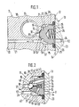
- FIG. 1 shows a partial cross section through a block directional control valve with a first device for selecting and forwarding a pressure signal in a left-hand version
- FIG. 2 shows a second device in the right-hand version matching FIG. 1.
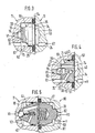
- FIG. 3 shows in section a third device for left-hand execution and in FIG. 4 the right-hand execution suitable for this.
- FIG. 5 shows in section a fifth device with a double arrangement of a left and a right version in adjacent flange surfaces.
- FIG. 1 shows a simplified representation of a partial cross section through the housing 10 of a first block directional control valve 11, on the first flange surface 12 of which a second block directional control valve 13 with its second flange surface 14 is attached.
- a blind hole-like recess 15 is arranged in the housing 10, the bottom 16 of which extends at a distance from a slide bore 17.
- a first control channel 18 leads into the floor 16 and transmits a pressure signal Y1 from the slide bore 17.
- the first control channel 18 runs coaxially with the cylindrically shaped recess 15, its opening into the bottom 16 being designed as a conical valve seat 19.
- a second control channel 21 runs in the housing 10 parallel to the first control channel 18 and connects a second flange surface 22 on the housing 10 to the bottom 16 of the recess 15.
- This second control channel 21 runs at a distance from the slide bore 17 and opens between the tapered valve seat 19 and the outer diameter of the recess 15 in the bottom 16.
- a third control channel 24 runs in the housing 23 of the flanged second block directional valve 13
- third control channel 24 leads into the second flange surface 14 and transmits a pressure signal Y2 from a device (not shown in more detail) for the selection and forwarding of a pressure signal in the second block directional valve 13.
- the recess 15 is widened towards the first flange surface J2 by a recess 25, in which an O-ring 26 is arranged for sealing to the outside, which at the same time has a function as a captive device.
- the recess 15 in the housing 10 receives an insert body 27 which, in the left-hand version shown in FIG. 1, is designed as a one-piece rotating part.
- the insert body 27 is axially guided in the recess 15, the resulting radial gap 29 being dimensioned so large that it can easily transmit pressure signals.
- the insert body 27 On its inner end face 31, the insert body 27 has the actual closing member 32, the spherical sealing surface 33 of which cooperates with the conical valve seat 19 fixed to the housing.
- a circular sealing strip 35 is formed on an outer end face 34 of the insert body 27 and cooperates with the second flange surface 14 of the adjacent block directional control valve 13 in the manner of a seat valve.
- the diameter of the sealing strip 35 is chosen to be as large as possible, and almost corresponds to the outer diameter of the insert body 27, so that the opening of the third control channel 24 into the second flange surface 14 lies within the area enclosed by the sealing strip 35.
- the insert body 27 is biased by a weak spring 36, which is supported on the second flange surface 14, in the direction of a preferred position in which its sealing surface 33 bears against the conical valve seat 19, while the sealing strip 35 lifts off the second flange surface 14.
- the insert body 27 and the associated, correspondingly designed recess 15 are parts of a first device 37 for selecting and forwarding a pressure signal in a block directional valve 11.
- the one-piece insert body 27 forms the valve member of a shuttle valve, in which the first (18) and the third control channel 24 form the side connections, while the second control channel 21 represents the center connection of the shuttle valve, via which the higher of the two incoming pressure signals YJ, Y2 continues is conducted as a pressure signal Y.
- the insert body 27 delimits an annular space 38 in the recess 15, which is connected to the second control channel 21 and whose connections to the side connections 18, 24 can be switched on or off alternately.
- the higher pressure signal Y2 can also build up in the annular space 38 via the opened sealing strip 35 and the radial gap 29 and will be via transmit the second control channel 21 to the second flange surface 22 as a pressure signal Y.
- the annular space 38 is blocked by the closing member 32 from the first control channel 18.
- the insert body 27 Apart from the weak force of the spring 36, the insert body 27 becomes pressed with a force on the conical valve seat 19, which results from the pressure difference between the two pressure signals Y2 and Y1 in connection with a pressurized surface, which is determined by the effective seat diameter on the closing member 32.
- FIG. 1 therefore shows a left-hand version of the first control device 37, in which the higher signal is selected and continued from two incoming pressure signals Y1 and Y2, while the lower pressure signal is blocked.
- a control block is referred to as a left-hand version if the pressure medium inflow, viewed from the operating side, is arranged to the left of the individual block valves 11 and 13 and the maximum control pressure signal must therefore be fed back there.
- FIG. 2 shows a second device 40 for selecting and forwarding a pressure signal in a block directional control valve in a simplified representation and in a construction as a right-hand version.
- the housings 10 and 23 of the two block directional valves 11 or 13 retained unchanged as in Figure 1; however, the recess 15 accommodates another, second insert body 41 in the housing 10.
- the second insert body 41 differs from the first insert body 27 according to FIG. 1 primarily in that it no longer assumes the function of a closing element itself, but instead has additional components inside for the shuttle valve function.
- the second insert body 41 is now firmly arranged in the housing 10. It is centered in the recess 15 with a collar 42, a sealing ring 43 ensuring radial sealing. With an end-side sealing cone 44, the second insert body 41 is pressed tightly and firmly onto the conical valve seat 19, as a result of which the annular space 38 is shut off.
- the sealing cone 44 encloses a recessed blind hole 45, which is introduced from the inner end face 31 and whose shoulder forms an inner valve seat 46.
- a spherical closing member 48 is guided, which is assigned to the shuttle valve function.
- the outer section 47 is chosen larger in diameter than the first control channel 18, so that the valve seat 19 fixed to the housing can also cooperate with the spherical closing member 48.
- a transverse bore 51 extends from an inner section 49 of the blind bore 45 into the annular space 38, which is connected to the second control channel 21.
- an oblique bore 52 leads from the outer section 47 of the blind hole 45 to the outer end face 34 of the second insert body 41, where it has a connection with the third control channel 24 in the second block directional valve 13 via a flat recess 53.
- a weak spring 54 arranged in the blind bore 45 brings about a preferred position of the spherical closing member 48 in the position shown.
- the spherical closing member 48 lies against its force against the weak spring 54 on its inner valve seat 46 and blocks the connection to the second control channel 2J. At the same time, the closing member 48 opens the connection from the first control channel 18 via the valve seat 19, the oblique bore 52 and the recess 53 to the third control channel 24, so that the larger pressure signal Y is in turn continued to the right there.
- FIG. 3 shows a third device 60 in the left-hand version, which differs from that according to FIG. 1 as follows, the same reference symbols being used for the same components.
- the first block directional control valve 11 has a different housing 61, in which the conical valve seat 19 is now reached through a valve seat bore 62.
- This valve seat bore 62 is designed in terms of depth and outer diameter in such a way that it forms with the spherical closing element required for a right-hand version the alternating valve function can work together.
- the second block directional control valve 13 has a different housing 63, with a countersink 64 in the second flange surface 14, the countersink 64 cutting the third control channel 24, which ends at a distance from the second flange surface 14.
- the recess 15 receives a third insert body 65 which, in addition to its sealing strip 35 on the outer end face 34, is also formed on the inner end face 31 with a flat seat 66.
- the diameter of this flat seat 66 is larger than the valve seat bore 62, but smaller than the diameter of the sealing strip 35.
- the third insert body 65 is in turn guided with a radial gap 29 in the recess 15 and, due to its axial mobility, can itself function the closing member in a shuttle valve take over.
- the mode of operation of the third device 60 therefore largely corresponds to that of the first device 37 according to FIG. 1, the flat seat 66 interacting with the base 16 determining an effective pressure area.
- the coaxial rotation 64 in the housing 63 is intended to accommodate unevenness on the outer end face 34 on the third insert body 65, as is e.g. in the case of one-sided turning machining can arise from turning sleeves. Since the third control channel 24 no longer has to be drilled into the second flange surface 14, it can lie on the same diameter with the sealing strip 35, which favors a more compact design of the third device 60.
- FIG. 4 shows, in a simplified manner, a section through a fourth device 70 in a right-hand embodiment, the same housings 61 and 63 as in FIG. 3 being used.
- the right-hand version 70 differs from the associated left-hand version 60 only by a different, fourth insert body 71.
- the fourth insert body 71 is arranged in a manner corresponding to the second insert body 41 according to FIG. 2 in the recess 15 of the housing 61, for which purpose it has the collar 42 with the sealing ring 43. Furthermore, the fourth insert body 71 correspondingly has a blind hole 45 with an inner valve seat 46, an inner section 49 and a transverse hole 51 leading from the latter to the annular space 38. An outer section 72 of the blind hole 45 is now shorter, so that it just closes the closing member 48 can record. This outer section 72 opens into a recess 73 delimited by the flat seat 66, from which a longitudinal bore 74 running parallel to the blind hole bore 45 extends to the outer end face 34 on the fourth insert body 71.
- the mode of operation of the fourth device 70 corresponds essentially to that of the right-hand version 40 according to FIG. 2, although the spherical closing member 48 can alternately assume its end positions in the valve seat bore 62 fixed to the housing or in the outer section 72 of the fourth insert body 71.
- the recess 73 assumes the function of a center connection in the shuttle valve, via which the selected, higher pressure is passed on.
- FIG. 5 shows a fifth device 80 with a double arrangement of shuttle valves, which is required when a shuttle function is required in each of the adjacent flange surfaces.
- the second device 40 according to FIG. 2 is arranged as a right-hand version, to which two pressure signals Y1 and Y2 are input.
- a first insert body 27 according to FIG. 1 is inserted in an adjacent connecting plate 81 with the same recess 15.
- a pressure signal Y3 can thus be entered in the connection plate 81 via a first control channel 82, e.g. can come from an associated steering committee.
- the maximum signal Y can finally be tapped from the pressure signals Y1 to Y3 and passed on to the controller of a variable displacement pump.
- the insert bodies being essentially designed as simple turned parts, as can be produced by preferably axial internal and external machining. While a one-piece rotating part is sufficient for the left-hand version, the insert part for a right-hand version must accommodate the actual closing element of the shuttle valve function.
- the simple construction of the insert body is achieved in a particularly expedient manner by the essentially axial seal, preferably metallic sealing compound be used.
- the first insert body 27 a possible radial impact error can be absorbed in an advantageous manner by the spherical sealing surface 33, whose associated ball diameter is smaller than the maximum diameter of the insert body 27.
- the insert bodies are designed in such a way that they can be arranged against one another if required if two changing functions are necessary in a flange surface.
- a simple and compact design of the devices is favored according to FIG. 3 and if the flange surface covering a recess is provided with a suitable countersink in order to compensate for inaccurate shapes of the insert bodies.
- protection against loss of the spherical closing member 48 can be achieved in a simple manner if the associated sealing cone 44 is slightly caulked inwards.
- the 0-rings 26 in the recesses 25 simultaneously take on the function of securing against loss, as long as the block directional control valves 11 are not combined to form a control block composed of several valves.
Landscapes
- Engineering & Computer Science (AREA)
- Physics & Mathematics (AREA)
- Fluid Mechanics (AREA)
- Mechanical Engineering (AREA)
- General Engineering & Computer Science (AREA)
- Multiple-Way Valves (AREA)
- Valve Housings (AREA)
- Fluid-Pressure Circuits (AREA)
Applications Claiming Priority (2)
| Application Number | Priority Date | Filing Date | Title |
|---|---|---|---|
| DE19853512014 DE3512014A1 (de) | 1985-04-02 | 1985-04-02 | Hydraulische einrichtung zur auswahl und weiterleitung eines drucksignals in einem blockwegeventil |
| DE3512014 | 1985-04-02 |
Publications (2)
| Publication Number | Publication Date |
|---|---|
| EP0197314A1 true EP0197314A1 (fr) | 1986-10-15 |
| EP0197314B1 EP0197314B1 (fr) | 1988-06-08 |
Family
ID=6267094
Family Applications (1)
| Application Number | Title | Priority Date | Filing Date |
|---|---|---|---|
| EP86103078A Expired EP0197314B1 (fr) | 1985-04-02 | 1986-03-07 | Dispositif hydraulique pour la sélection et la transmission d'un signal de pression dans une soupape directionnelle assemblée par blocs |
Country Status (3)
| Country | Link |
|---|---|
| EP (1) | EP0197314B1 (fr) |
| JP (1) | JPH06100291B2 (fr) |
| DE (2) | DE3512014A1 (fr) |
Cited By (2)
| Publication number | Priority date | Publication date | Assignee | Title |
|---|---|---|---|---|
| FR2689575A1 (fr) * | 1992-04-06 | 1993-10-08 | Rexroth Sigma | Distributeur hydraulique à compensation de pression et une sélection de pression maximale pour piloter une pompe et commande hydraulique multiple incluant de tels distributeurs. |
| EP3581807A1 (fr) * | 2018-06-15 | 2019-12-18 | Murata Machinery, Ltd. | Unité de vanne à solénoïde et enrouleur automatique |
Families Citing this family (5)
| Publication number | Priority date | Publication date | Assignee | Title |
|---|---|---|---|---|
| JPH01216174A (ja) * | 1988-02-22 | 1989-08-30 | Diesel Kiki Co Ltd | シャトル弁装置 |
| DE4142293A1 (de) * | 1991-12-20 | 1993-07-01 | Wabco Westinghouse Fahrzeug | 3/2-wegeventileinrichtung |
| DE4344370A1 (de) * | 1993-12-24 | 1995-06-29 | Wabco Vermoegensverwaltung | Ventileinrichtung |
| DE102005011138B4 (de) * | 2005-03-10 | 2016-08-04 | Bosch Rexroth Aktiengesellschaft | Vorgesteuertes Druckabschaltventil |
| DE102010018043A1 (de) | 2010-04-23 | 2011-10-27 | Robert Bosch Gmbh | Stützring für einen Dichtring |
Citations (7)
| Publication number | Priority date | Publication date | Assignee | Title |
|---|---|---|---|---|
| CH130959A (fr) * | 1927-05-16 | 1929-01-15 | Vickers Ltd | Dispositif servant à délivrer un fluide sous pression. |
| US2646815A (en) * | 1951-06-01 | 1953-07-28 | Leon C Leventhal | Vacuum breaker for water supply systems |
| GB827510A (en) * | 1957-02-01 | 1960-02-03 | Lang Pneumatic Ltd | Improvements in or relating to valves for controlling the flow of pressure fluids |
| DE2423243A1 (de) * | 1973-09-21 | 1975-03-27 | Koehring Co | Hydraulisches steuerventil |
| US4145958A (en) * | 1977-12-02 | 1979-03-27 | Borg-Warner Corporation | Fluid control system with automatically actuated motor port lock-out valves |
| WO1981001316A1 (fr) * | 1979-11-08 | 1981-05-14 | C Habiger | Separateur de charges ameliore |
| DE3309998A1 (de) * | 1983-03-19 | 1984-09-20 | Robert Bosch Gmbh, 7000 Stuttgart | Hydraulische einrichtung zur auswahl und weiterleitung eines drucksignals in einem blockwegeventil |
-
1985
- 1985-04-02 DE DE19853512014 patent/DE3512014A1/de not_active Withdrawn
-
1986
- 1986-03-07 DE DE8686103078T patent/DE3660292D1/de not_active Expired
- 1986-03-07 EP EP86103078A patent/EP0197314B1/fr not_active Expired
- 1986-03-26 JP JP61066124A patent/JPH06100291B2/ja not_active Expired - Lifetime
Patent Citations (7)
| Publication number | Priority date | Publication date | Assignee | Title |
|---|---|---|---|---|
| CH130959A (fr) * | 1927-05-16 | 1929-01-15 | Vickers Ltd | Dispositif servant à délivrer un fluide sous pression. |
| US2646815A (en) * | 1951-06-01 | 1953-07-28 | Leon C Leventhal | Vacuum breaker for water supply systems |
| GB827510A (en) * | 1957-02-01 | 1960-02-03 | Lang Pneumatic Ltd | Improvements in or relating to valves for controlling the flow of pressure fluids |
| DE2423243A1 (de) * | 1973-09-21 | 1975-03-27 | Koehring Co | Hydraulisches steuerventil |
| US4145958A (en) * | 1977-12-02 | 1979-03-27 | Borg-Warner Corporation | Fluid control system with automatically actuated motor port lock-out valves |
| WO1981001316A1 (fr) * | 1979-11-08 | 1981-05-14 | C Habiger | Separateur de charges ameliore |
| DE3309998A1 (de) * | 1983-03-19 | 1984-09-20 | Robert Bosch Gmbh, 7000 Stuttgart | Hydraulische einrichtung zur auswahl und weiterleitung eines drucksignals in einem blockwegeventil |
Cited By (4)
| Publication number | Priority date | Publication date | Assignee | Title |
|---|---|---|---|---|
| FR2689575A1 (fr) * | 1992-04-06 | 1993-10-08 | Rexroth Sigma | Distributeur hydraulique à compensation de pression et une sélection de pression maximale pour piloter une pompe et commande hydraulique multiple incluant de tels distributeurs. |
| EP0566449A1 (fr) * | 1992-04-06 | 1993-10-20 | Rexroth-Sigma | Distributeur hydraulique combinant la compensation de pression et la sélection de pression maximale |
| US5305789A (en) * | 1992-04-06 | 1994-04-26 | Rexroth-Sigma | Hydraulic directional control valve combining pressure compensation and maximum pressure selection for controlling a feed pump, and multiple hydraulic control apparatus including a plurality of such valves |
| EP3581807A1 (fr) * | 2018-06-15 | 2019-12-18 | Murata Machinery, Ltd. | Unité de vanne à solénoïde et enrouleur automatique |
Also Published As
| Publication number | Publication date |
|---|---|
| EP0197314B1 (fr) | 1988-06-08 |
| JPH06100291B2 (ja) | 1994-12-12 |
| JPS61233273A (ja) | 1986-10-17 |
| DE3660292D1 (en) | 1988-07-14 |
| DE3512014A1 (de) | 1986-10-02 |
Similar Documents
| Publication | Publication Date | Title |
|---|---|---|
| EP0374438B1 (fr) | Distributeur piloté | |
| DE69100356T2 (de) | Hydraulisches Steuerventilsystem in Blockbauweise. | |
| DE69704592T2 (de) | Vorgesteuertes Wahlventil | |
| DE3011791A1 (de) | Ventileinsatz sowie unter verwendung desselben hergestelltes ventil | |
| DE69617126T2 (de) | Vorgesteuertes Umschaltventil | |
| EP0918678B1 (fr) | Dispositif de commande electrohydraulique | |
| EP0197314B1 (fr) | Dispositif hydraulique pour la sélection et la transmission d'un signal de pression dans une soupape directionnelle assemblée par blocs | |
| EP2577122B1 (fr) | Soupape à voies multiples et méthode pour l'actionner | |
| EP1939461A2 (fr) | Vanne pneumatique modulaire à tiroir | |
| EP1508732B1 (fr) | Dispositif de soupape | |
| EP0686775B2 (fr) | Dispositif de vanne électropneumatique | |
| DE2435685A1 (de) | Zylinder-kolben-steuerventil | |
| DE4011908C2 (fr) | ||
| EP0319670B1 (fr) | Valve à relais | |
| DE1088303B (de) | Steuervorrichtung mit einem Steuerschieber und einem ihm zugeordneten Hilfsschieber | |
| DE3309998A1 (de) | Hydraulische einrichtung zur auswahl und weiterleitung eines drucksignals in einem blockwegeventil | |
| DE3625058A1 (de) | Ventil | |
| EP1035331B1 (fr) | Distributeur piloté | |
| DE19713313A1 (de) | Steuerbare Ventileinrichtung | |
| EP0129726B1 (fr) | Soupape hydraulique de commande avec une structure de logement | |
| EP0463394A1 (fr) | Distributeur à commande électromagnétique | |
| EP0655558B1 (fr) | Soupape pneumatique avec au moins deux modules fixés l'un à l'autre | |
| EP1042616B1 (fr) | Distributeur 4/2 pneumatique controle par impulsions | |
| DE10034935C2 (de) | Mehrwegeventil | |
| DE2903627C2 (fr) |
Legal Events
| Date | Code | Title | Description |
|---|---|---|---|
| PUAI | Public reference made under article 153(3) epc to a published international application that has entered the european phase |
Free format text: ORIGINAL CODE: 0009012 |
|
| AK | Designated contracting states |
Kind code of ref document: A1 Designated state(s): DE FR GB IT |
|
| 17P | Request for examination filed |
Effective date: 19861126 |
|
| 17Q | First examination report despatched |
Effective date: 19870722 |
|
| GRAA | (expected) grant |
Free format text: ORIGINAL CODE: 0009210 |
|
| AK | Designated contracting states |
Kind code of ref document: B1 Designated state(s): DE FR GB IT |
|
| GBT | Gb: translation of ep patent filed (gb section 77(6)(a)/1977) | ||
| REF | Corresponds to: |
Ref document number: 3660292 Country of ref document: DE Date of ref document: 19880714 |
|
| ET | Fr: translation filed | ||
| ITF | It: translation for a ep patent filed | ||
| PLBE | No opposition filed within time limit |
Free format text: ORIGINAL CODE: 0009261 |
|
| STAA | Information on the status of an ep patent application or granted ep patent |
Free format text: STATUS: NO OPPOSITION FILED WITHIN TIME LIMIT |
|
| 26N | No opposition filed | ||
| ITTA | It: last paid annual fee | ||
| PGFP | Annual fee paid to national office [announced via postgrant information from national office to epo] |
Ref country code: GB Payment date: 19990223 Year of fee payment: 14 |
|
| PG25 | Lapsed in a contracting state [announced via postgrant information from national office to epo] |
Ref country code: GB Free format text: LAPSE BECAUSE OF NON-PAYMENT OF DUE FEES Effective date: 20000307 |
|
| GBPC | Gb: european patent ceased through non-payment of renewal fee |
Effective date: 20000307 |
|
| PGFP | Annual fee paid to national office [announced via postgrant information from national office to epo] |
Ref country code: FR Payment date: 20010323 Year of fee payment: 16 |
|
| PG25 | Lapsed in a contracting state [announced via postgrant information from national office to epo] |
Ref country code: FR Free format text: LAPSE BECAUSE OF NON-PAYMENT OF DUE FEES Effective date: 20021129 |
|
| REG | Reference to a national code |
Ref country code: FR Ref legal event code: ST |
|
| PGFP | Annual fee paid to national office [announced via postgrant information from national office to epo] |
Ref country code: DE Payment date: 20030425 Year of fee payment: 18 |
|
| PG25 | Lapsed in a contracting state [announced via postgrant information from national office to epo] |
Ref country code: DE Free format text: LAPSE BECAUSE OF NON-PAYMENT OF DUE FEES Effective date: 20041001 |
|
| PG25 | Lapsed in a contracting state [announced via postgrant information from national office to epo] |
Ref country code: IT Free format text: LAPSE BECAUSE OF NON-PAYMENT OF DUE FEES;WARNING: LAPSES OF ITALIAN PATENTS WITH EFFECTIVE DATE BEFORE 2007 MAY HAVE OCCURRED AT ANY TIME BEFORE 2007. THE CORRECT EFFECTIVE DATE MAY BE DIFFERENT FROM THE ONE RECORDED. Effective date: 20050307 |