EP3581807A1 - Unité de vanne à solénoïde et enrouleur automatique - Google Patents
Unité de vanne à solénoïde et enrouleur automatique Download PDFInfo
- Publication number
- EP3581807A1 EP3581807A1 EP19165457.3A EP19165457A EP3581807A1 EP 3581807 A1 EP3581807 A1 EP 3581807A1 EP 19165457 A EP19165457 A EP 19165457A EP 3581807 A1 EP3581807 A1 EP 3581807A1
- Authority
- EP
- European Patent Office
- Prior art keywords
- air
- solenoid valve
- flow path
- casing
- package
- Prior art date
- Legal status (The legal status is an assumption and is not a legal conclusion. Google has not performed a legal analysis and makes no representation as to the accuracy of the status listed.)
- Withdrawn
Links
- 238000004804 winding Methods 0.000 description 63
- 238000012806 monitoring device Methods 0.000 description 3
- 238000004590 computer program Methods 0.000 description 2
- 230000007547 defect Effects 0.000 description 2
- 230000006870 function Effects 0.000 description 2
- 230000007246 mechanism Effects 0.000 description 2
- 230000002093 peripheral effect Effects 0.000 description 2
- 229920002430 Fibre-reinforced plastic Polymers 0.000 description 1
- 230000005856 abnormality Effects 0.000 description 1
- 238000010276 construction Methods 0.000 description 1
- 230000008878 coupling Effects 0.000 description 1
- 238000010168 coupling process Methods 0.000 description 1
- 238000005859 coupling reaction Methods 0.000 description 1
- 239000011151 fibre-reinforced plastic Substances 0.000 description 1
- 239000003365 glass fiber Substances 0.000 description 1
- 238000009434 installation Methods 0.000 description 1
- 238000012986 modification Methods 0.000 description 1
- 230000004048 modification Effects 0.000 description 1
- 238000012544 monitoring process Methods 0.000 description 1
- 239000000126 substance Substances 0.000 description 1
- 238000011144 upstream manufacturing Methods 0.000 description 1
Images






Classifications
-
- F—MECHANICAL ENGINEERING; LIGHTING; HEATING; WEAPONS; BLASTING
- F15—FLUID-PRESSURE ACTUATORS; HYDRAULICS OR PNEUMATICS IN GENERAL
- F15B—SYSTEMS ACTING BY MEANS OF FLUIDS IN GENERAL; FLUID-PRESSURE ACTUATORS, e.g. SERVOMOTORS; DETAILS OF FLUID-PRESSURE SYSTEMS, NOT OTHERWISE PROVIDED FOR
- F15B13/00—Details of servomotor systems ; Valves for servomotor systems
- F15B13/02—Fluid distribution or supply devices characterised by their adaptation to the control of servomotors
- F15B13/06—Fluid distribution or supply devices characterised by their adaptation to the control of servomotors for use with two or more servomotors
- F15B13/08—Assemblies of units, each for the control of a single servomotor only
- F15B13/0803—Modular units
- F15B13/0807—Manifolds
- F15B13/0814—Monoblock manifolds
-
- B—PERFORMING OPERATIONS; TRANSPORTING
- B65—CONVEYING; PACKING; STORING; HANDLING THIN OR FILAMENTARY MATERIAL
- B65H—HANDLING THIN OR FILAMENTARY MATERIAL, e.g. SHEETS, WEBS, CABLES
- B65H54/00—Winding, coiling, or depositing filamentary material
- B65H54/02—Winding and traversing material on to reels, bobbins, tubes, or like package cores or formers
- B65H54/22—Automatic winding machines, i.e. machines with servicing units for automatically performing end-finding, interconnecting of successive lengths of material, controlling and fault-detecting of the running material and replacing or removing of full or empty cores
- B65H54/26—Automatic winding machines, i.e. machines with servicing units for automatically performing end-finding, interconnecting of successive lengths of material, controlling and fault-detecting of the running material and replacing or removing of full or empty cores having one or more servicing units moving along a plurality of fixed winding units
-
- B—PERFORMING OPERATIONS; TRANSPORTING
- B65—CONVEYING; PACKING; STORING; HANDLING THIN OR FILAMENTARY MATERIAL
- B65H—HANDLING THIN OR FILAMENTARY MATERIAL, e.g. SHEETS, WEBS, CABLES
- B65H54/00—Winding, coiling, or depositing filamentary material
- B65H54/70—Other constructional features of yarn-winding machines
- B65H54/72—Framework; Casings; Coverings
-
- B—PERFORMING OPERATIONS; TRANSPORTING
- B65—CONVEYING; PACKING; STORING; HANDLING THIN OR FILAMENTARY MATERIAL
- B65H—HANDLING THIN OR FILAMENTARY MATERIAL, e.g. SHEETS, WEBS, CABLES
- B65H2701/00—Handled material; Storage means
- B65H2701/30—Handled filamentary material
- B65H2701/31—Textiles threads or artificial strands of filaments
-
- F—MECHANICAL ENGINEERING; LIGHTING; HEATING; WEAPONS; BLASTING
- F15—FLUID-PRESSURE ACTUATORS; HYDRAULICS OR PNEUMATICS IN GENERAL
- F15B—SYSTEMS ACTING BY MEANS OF FLUIDS IN GENERAL; FLUID-PRESSURE ACTUATORS, e.g. SERVOMOTORS; DETAILS OF FLUID-PRESSURE SYSTEMS, NOT OTHERWISE PROVIDED FOR
- F15B2211/00—Circuits for servomotor systems
- F15B2211/20—Fluid pressure source, e.g. accumulator or variable axial piston pump
- F15B2211/205—Systems with pumps
- F15B2211/20576—Systems with pumps with multiple pumps
- F15B2211/20592—Combinations of pumps for supplying high and low pressure
-
- F—MECHANICAL ENGINEERING; LIGHTING; HEATING; WEAPONS; BLASTING
- F15—FLUID-PRESSURE ACTUATORS; HYDRAULICS OR PNEUMATICS IN GENERAL
- F15B—SYSTEMS ACTING BY MEANS OF FLUIDS IN GENERAL; FLUID-PRESSURE ACTUATORS, e.g. SERVOMOTORS; DETAILS OF FLUID-PRESSURE SYSTEMS, NOT OTHERWISE PROVIDED FOR
- F15B2211/00—Circuits for servomotor systems
- F15B2211/20—Fluid pressure source, e.g. accumulator or variable axial piston pump
- F15B2211/265—Control of multiple pressure sources
-
- F—MECHANICAL ENGINEERING; LIGHTING; HEATING; WEAPONS; BLASTING
- F15—FLUID-PRESSURE ACTUATORS; HYDRAULICS OR PNEUMATICS IN GENERAL
- F15B—SYSTEMS ACTING BY MEANS OF FLUIDS IN GENERAL; FLUID-PRESSURE ACTUATORS, e.g. SERVOMOTORS; DETAILS OF FLUID-PRESSURE SYSTEMS, NOT OTHERWISE PROVIDED FOR
- F15B2211/00—Circuits for servomotor systems
- F15B2211/30—Directional control
- F15B2211/305—Directional control characterised by the type of valves
- F15B2211/3052—Shuttle valves
-
- F—MECHANICAL ENGINEERING; LIGHTING; HEATING; WEAPONS; BLASTING
- F15—FLUID-PRESSURE ACTUATORS; HYDRAULICS OR PNEUMATICS IN GENERAL
- F15B—SYSTEMS ACTING BY MEANS OF FLUIDS IN GENERAL; FLUID-PRESSURE ACTUATORS, e.g. SERVOMOTORS; DETAILS OF FLUID-PRESSURE SYSTEMS, NOT OTHERWISE PROVIDED FOR
- F15B2211/00—Circuits for servomotor systems
- F15B2211/30—Directional control
- F15B2211/305—Directional control characterised by the type of valves
- F15B2211/3056—Assemblies of multiple valves
- F15B2211/3059—Assemblies of multiple valves having multiple valves for multiple output members
-
- F—MECHANICAL ENGINEERING; LIGHTING; HEATING; WEAPONS; BLASTING
- F15—FLUID-PRESSURE ACTUATORS; HYDRAULICS OR PNEUMATICS IN GENERAL
- F15B—SYSTEMS ACTING BY MEANS OF FLUIDS IN GENERAL; FLUID-PRESSURE ACTUATORS, e.g. SERVOMOTORS; DETAILS OF FLUID-PRESSURE SYSTEMS, NOT OTHERWISE PROVIDED FOR
- F15B2211/00—Circuits for servomotor systems
- F15B2211/30—Directional control
- F15B2211/305—Directional control characterised by the type of valves
- F15B2211/3056—Assemblies of multiple valves
- F15B2211/3059—Assemblies of multiple valves having multiple valves for multiple output members
- F15B2211/30595—Assemblies of multiple valves having multiple valves for multiple output members with additional valves between the groups of valves for multiple output members
-
- F—MECHANICAL ENGINEERING; LIGHTING; HEATING; WEAPONS; BLASTING
- F15—FLUID-PRESSURE ACTUATORS; HYDRAULICS OR PNEUMATICS IN GENERAL
- F15B—SYSTEMS ACTING BY MEANS OF FLUIDS IN GENERAL; FLUID-PRESSURE ACTUATORS, e.g. SERVOMOTORS; DETAILS OF FLUID-PRESSURE SYSTEMS, NOT OTHERWISE PROVIDED FOR
- F15B2211/00—Circuits for servomotor systems
- F15B2211/30—Directional control
- F15B2211/32—Directional control characterised by the type of actuation
- F15B2211/327—Directional control characterised by the type of actuation electrically or electronically
-
- F—MECHANICAL ENGINEERING; LIGHTING; HEATING; WEAPONS; BLASTING
- F15—FLUID-PRESSURE ACTUATORS; HYDRAULICS OR PNEUMATICS IN GENERAL
- F15B—SYSTEMS ACTING BY MEANS OF FLUIDS IN GENERAL; FLUID-PRESSURE ACTUATORS, e.g. SERVOMOTORS; DETAILS OF FLUID-PRESSURE SYSTEMS, NOT OTHERWISE PROVIDED FOR
- F15B2211/00—Circuits for servomotor systems
- F15B2211/80—Other types of control related to particular problems or conditions
- F15B2211/885—Control specific to the type of fluid, e.g. specific to magnetorheological fluid
- F15B2211/8855—Compressible fluids, e.g. specific to pneumatics
Definitions
- the present invention relates to a solenoid valve unit and an automatic winder.
- Japanese Patent Application Laid-Open No. 2001-106434 discloses a pipe joined device in which plural air pipes are joined detachably.
- the pipe joined device disclosed in Japanese Patent Application Laid-Open No. 2001-106434 includes an opening-closing part constituted by a spindle valve body or the like and a valve operating part including a lever or the like.
- it is attempted to simultaneously open or close a plurality of air paths by operating the valve operating part.
- One object of the present invention is to provide a solenoid valve unit and an automatic winder that can reduce the necessary resources.
- a solenoid valve unit includes a casing that houses therein a first flow path through which a first air flows, a second flow path through which a second air having a pressure higher than the first air flows, and a third flow path connected via a shuttle valve to a downstream side of the first flow path and to a downstream side of the second flow path; a first solenoid valve that is integrated with the casing and controls flow of the first air to the first flow path; and a second solenoid valve that is integrated with the casing and controls flow of the second air to the second flow path.
- the casing includes a first outlet through which one of the first air and the second air flowing through the third flow path flows out.
- An automatic winder includes a holding part that holds a package by sandwiching the package; a brake section that controls a holding force and braking of the holding part according to the pressure of supplied air; and the above explained solenoid valve unit.
- the solenoid valve unit when holding the package rotatably via the holding part by using the brake section, sets the first solenoid valve in an open state and sets the second solenoid valve in a closed state, and supplies the first air to the brake section via the first outlet, and, when braking the package via the holding part by using the brake section, sets the second solenoid valve in an open state and supplies the second air to the brake section via the first outlet.
- an automatic winder 1 includes a plurality of winder units 3 arranged side by side, a main controller 5, and a doffing device 7.
- the main controller 5 can communicate with each of the winder units 3.
- An operator of the automatic winder 1 can collectively manage the winder units 3 by appropriately operating the main controller 5.
- Each of the winder units 3 forms a package P by unwinding a spun yarn Y from a yarn supplying bobbin SB and simultaneously winding the spun yarn Y around a winding bobbin WB while traversing the spun yarn Y.
- the doffing device 7 travels to the position of the winder unit 3 and replaces the full package with an empty winding bobbin WB.
- the winder unit 3 includes a unit control section 10, a yarn supplying device 12, and a winding device 14.
- the unit control section 10 includes, for example, a CPU (Central Processing Unit) and a ROM (Read Only Memory).
- a computer program for controlling various parts of the winder unit 3 is stored in the ROM.
- the CPU executes the computer program stored in the ROM.
- the yarn supplying device 12 supports at a predetermined position a yarn supplying bobbin SB placed on a not-shown conveying tray.
- the yarn supplying device 12 unwinds the spun yarn Y from the yarn supplying bobbin SB and pulls the unwound spun yarn Y from the yarn supplying bobbin SB.
- the yarn supplying device 12 supplies the spun yarn Y.
- the yarn supplying device 12 is not limited to the conveying tray type device but can be a magazine type device, for example.
- the winding device 14 includes a cradle 16 and a winding drum 18.
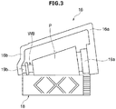
- the cradle 16 holds a winding bobbin WB (or the package P) in a rotatable manner by sandwiching the winding bobbin WB between winding bobbin holders (holding parts) 19a and 19b (see FIG. 3 ).
- the cradle 16 can be switched between a state in which the package P is in contact with the winding drum 18 and a state in which the package P is separated from the winding drum 18 (lift-up state) by operation of a later-described lift-up cylinder 57.
- the winding drum 18 traverses the spun yarn Y on the surface of the package P while rotating the package P.
- the winding drum 18 is rotationally driven by a not-shown drum driving motor.
- the winding drum 18 is rotationally driven while the outer peripheral surface of the package P in contact with the winding drum 18, the package P is driven to rotate.
- a helical traversing groove is formed on the outer peripheral surface of the winding drum 18.
- the spun yarn Y unwound from the yarn supplying bobbin SB is wound onto the surface of the package P while being traversed for a certain width by the traversing groove. As a result, the package P having a certain winding width can be formed.
- Each of the winder units 3 includes, in a yarn running path between the yarn supplying device 12 and the winding device 14, in the below order from the yarn supplying device 12 side, an unwinding assisting device 20, a tension applying device 22, a tension detecting device 24, a yarn joining device 26, and a yarn monitoring device 28.
- a first catching and guiding device 30 and a second catching and guiding device 32 are arranged near the yarn joining device 26.
- the unwinding assisting device 20 prevents the spun yarn Y that is being unwound from the yarn supplying bobbin SB from being excessively swung because of the centrifugal force thereby appropriately unwinding the spun yarn Y from the yarn supplying bobbin SB.
- the tension applying device 22 applies a predetermined tension to the running spun yarn Y.
- the tension applying device 22 is a gate type device including movable comb teeth and fixed comb teeth opposing the movable comb teeth.
- the tension detecting device 24 detects the tension of the running spun yarn Y at a position between the yarn supplying device 12 and the winding device 14.
- the yarn joining device 26 joins the spun yarn Y (lower yarn) from the yarn supplying device 12 and the spun yarn Y (upper yarn) from the winding device 14.
- the yarn monitoring device 28 monitors the state of the spun yarn Y running on the yarn path and detects the presence or absence of the yarn defect based on the result of the monitoring.
- the yarn defect is, for example, at least one among a thickness abnormality of the spun yarn Y, foreign substance contained in the spun yarn Y, a yarn breakage, and the like.
- the first catching and guiding device 30 can pivot from a waiting position on the yarn supplying device 12 side to a catching position on the winding device 14 side.
- the first catching and guiding device 30 catches the upper yarn at the catching position and guides the caught upper yarn to the yarn joining device 26.
- the second catching and guiding device 32 can pivot from a waiting position on the yarn supplying device 12 side to a catching position on the winding device 14 side.
- the second catching and guiding device 32 catches the lower yarn and guides the caught lower yarn to the yarn joining device 26.
- the cradle 16 holds the package P.
- the cradle 16 includes a pair of cradle arms 16a and 16b.
- the cradle arms 16a and 16b are rotatable around an axis.
- the cradle arms 16a and 16b can pivot toward or away from the winding drum 18.
- the winding bobbin holders 19a and 19b are rotatably mounted on the distal ends of the cradle arms 16a and 16b, respectively.
- the winding bobbin holders 19a and 19b are arranged opposing each other.
- the winding bobbin holders 19a and 19b constitute a holding part that holds the package P by sandwiching the package P.
- the winding bobbin WB is mounted on the cradle 16
- the winding bobbin holders 19a and 19b are attached to the axial ends of the winding bobbin WB.
- the winding bobbin holders 19a and 19b and the winding bobbin WB rotate integrally because of the frictional force.
- a package brake 51 is arranged at the distal end of the cradle arm 16a.
- the package brake 51 constitutes a brake section that controls a holding force and braking by the winding bobbin holders 19a and 19b according to the pressure of the air supplied thereto.
- the package brake 51 includes a housing 52, a bearing sleeve 53, a rotation support section 54, a first spring 55, and a second spring 56.
- the bearing sleeve 53 is movable and non-rotatable with respect to the housing 52.
- the rotation support section 54 is arranged inside the bearing sleeve 53.
- the rotation support section 54 supports in a rotatable manner a shaft extending from the winding bobbin holder 19a.
- the first spring 55 is arranged between a bottom surface of the housing 52 and the bearing sleeve 53.
- the first spring 55 applies an urging force on the bearing sleeve 53 so that the bearing sleeve 53 is pressed toward the winding bobbin holder 19a.
- the second spring 56 is arranged between the bearing sleeve 53 and the rotation support section 54. In this configuration, when no air is supplied to the housing 52, the winding bobbin holder 19a can rotate freely with respect to the bearing sleeve 53.
- the package brake (brake section) 51 is configured to simultaneously perform the rotation braking of the winding bobbin holder 19a and the pressing of the winding bobbin holder 19a toward the winding bobbin WB.
- the force acting on the bearing sleeve 53 is greater than or equal to a certain value but less than a predetermined value.
- the first air is compressed air having a pressure of, for example, 0.1 MPa to 0.2 MPa.
- the winding bobbin WB is sandwiched between the winding bobbin holders 19a and 19b with a strong force, but the winding bobbin WB rotation is not braked.
- some specifications may not require the first air.
- the pressure of the first air can be set to 0 MPa.
- the force acting on the bearing sleeve 53 becomes equal to or greater than the predetermined value.
- the second air is compressed air having a pressure of, for example, 0.3 MPa to 0.7 MPa.
- a cylinder rod of the lift-up cylinder 57 shown in FIG. 5 is connected to the cradle arm 16a.
- the lift-up cylinder 57 is a device that moves the cradle 16 so that the package P is separated from the winding drum 18.
- the lift-up cylinder 57 is driven when the second air is supplied. When the lift-up cylinder 57 extends, it is possible to rotate the cradle 16 so that the package P separates from the winding drum 18.
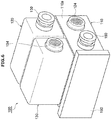
- each of the winder units 3 of the automatic winder 1 includes a solenoid valve unit 100 shown in FIGS. 5 , 6 , and 7 .
- the solenoid valve unit 100 is a device that can selectively switch between two air systems and output the air of the selected air system. More specifically, the solenoid valve unit 100 constitutes an air circuit that can selectively output one of the two airs, and also can output one of the two airs as it is. More specifically, the solenoid valve unit 100 outputs the first air when the first air is input, and when the second air is input while the first air is being input, the solenoid valve unit 100 substitutes the first air with the second air and also separately outputs the second air as it is.
- the solenoid valve unit 100 includes a casing 110, a first solenoid valve 120, and a second solenoid valve 130.
- the casing 110 is made of fiber reinforced plastic including glass fiber.
- the casing 110 houses a first flow path 111, a second flow path 112, a third flow path 113, a fourth flow path 114, and a fifth flow path 115.
- the first to fifth flow paths 111 to 115 are, for example, passages (holes) formed in the casing 110.
- the first flow path 111 is a flow path through which the first air output from the first solenoid valve 120 flows.
- the first flow path 111 is connected to an exit port of the first solenoid valve 120.
- the second flow path 112 is a flow path through which the second air output from the second solenoid valve 130 flows.
- the second flow path 112 is connected to an exit port of the second solenoid valve 130.
- the third flow path 113 is connected via a shuttle valve 140 to the downstream side of the first flow path 111 and to the downstream side of the second flow path 112.
- the third flow path 113 is a flow path through which one of the first air and the second air can flow.
- the fourth flow path 114 is connected in the middle of the second flow path 112.
- the fourth flow path 114 is a flow path through which a part of the second air flowing through the second flow path 112 flows.
- the fifth flow path 115 is a flow path through which the second air flows from a later-explained second input air coupler 160 to the second solenoid valve 130.
- the fifth flow path 115 is connected to an inlet port of the second solenoid valve 130.
- the shuttle valve 140 has an inlet connected to the first flow path 111, another inlet connected to the second flow path 112, and one outlet connected to the third flow path 113.
- the shuttle valve 140 is a valve in which the inlet on the high pressure side of the two inlets is connected to the outlet.
- the shuttle valve 140 outputs the first air to the third flow path 113 when the first air is input from the first flow path 111 but the second air is not input from the second flow path 112.
- the shuttle valve 140 outputs the second air on the high pressure side to the third flow path 113 when the first air is input from the first flow path 111 and the second air is input from the second flow path 112.
- the first solenoid valve 120 controls the flow of the first air to the first flow path 111. Specifically, the first solenoid valve 120 can allow or block the flow of the first air through the first flow path 111.
- the first solenoid valve 120 is an always-open type solenoid valve that permits the flow of the first air when no electric power is supplied to the first solenoid valve 120.
- the first solenoid valve 120 includes a solenoid part and a valve part.
- the first solenoid valve 120 is not particularly limited, and various known solenoid valves can be used as the first solenoid valve 120.
- the first solenoid valve 120 is integrated with the casing 110. In the present embodiment, the term "integrate" includes being physically one or being merged into each other (the same definition holds true in the below explanation).
- a part of the first solenoid valve 120 is constituted by the casing 110.
- the function of the first solenoid valve 120 is established by the presence of the casing 110.
- the second solenoid valve 130 controls the flow of the second air to the second flow path 112. Specifically, the second solenoid valve 130 can allow or block the flow of the second air to the second flow path 112.
- the second solenoid valve 130 is an always-closed type solenoid valve that blocks the flow of the second air when no electric power is supplied to the second solenoid valve 130.
- the second solenoid valve 130 includes a solenoid part and a valve part.
- the second solenoid valve 130 is not particularly limited, and various known solenoid valves can be used as the second solenoid valve 130.
- the second solenoid valve 130 is integrated with the casing 110. For example, a part of the second solenoid valve 130 is constituted by the casing 110.
- the function of the second solenoid valve 130 is established by the presence of the casing 110.
- the first solenoid valve 120 and the second solenoid valve 130 are arranged side by side and close to each other.
- the solenoid valve unit 100 includes a first input air coupler 150, the second input air coupler 160, a first output air coupler 170, and a second output air coupler 180.
- the first input air coupler 150 constitutes a first inlet for introducing the first air.
- the first input air coupler 150 (first inlet) is arranged on a side surface of the first solenoid valve 120.
- the first input air coupler 150 is connected to an inlet port of the first solenoid valve 120.
- the second input air coupler 160 constitutes a second inlet for introducing the second air.
- the second input air coupler (second inlet) 160 is arranged on a side surface 110a (see FIG. 6 ) of the casing 110.
- the second input air coupler 160 is connected to the upstream side of the fifth flow path 115.
- the first output air coupler 170 constitutes a first outlet through which one of the first air and the second air flowing through the third flow path 113 flows out.
- the first output air coupler 170 (first outlet) is provided on a side surface 110b (see FIG. 7 ), which opposes the side surface 110a, of the casing 110.
- the first output air coupler 170 is connected to the downstream side of the third flow path 113.
- the second output air coupler 180 constitutes a second outlet through which the second air flowing through the fourth flow path 114 flows out.
- the second output air coupler 180 is arranged on the side surface 110b of the casing 110 so as to be side by side of the first output air coupler 170.
- the second output air coupler 180 is connected to the downstream side of the fourth flow path 114.
- the casing 110 has an attaching part 190.
- the solenoid valve unit 100 is attached to a unit frame F by using a fastening member (screw or the like) via the attaching part 190 of the casing 110.
- a bracket B is interposed between the attaching part 190 and the unit frame F; however, this bracket B can be omitted.
- a cable C is connected to each of the first and second solenoid valves 120 and 130. Electric power is supplied to the first and second solenoid valves 120 and 130 via those cables C. The supply of the electric power to the first and second solenoid valves 120 and 130 is controlled by the unit control section 10.
- An air tube is connected to each of the first input air coupler 150, the second input air coupler 160, the first output air coupler 170, and the second output air coupler 180.
- the second air is not input from the second input air coupler 160 but the first air is input into the solenoid valve unit 100 from the first input air coupler 150. Because no electric power is supplied by the unit control section 10 to the first solenoid valve 120 and the second solenoid valve 130, the first solenoid valve 120 is set in an open state and the second solenoid valve 130 is set in a closed state.
- the first air flows through the first solenoid valve 120, the first flow path 111, then flows through the third flow path 113 via the shuttle valve 140, and finally the first air is supplied to the package brake 51 via the first output air coupler 170.
- the package P is held rotatably.
- the solenoid valve unit 100 when braking the package P via the winding bobbin holders 19a and 19b by using the package brake 51, in addition to inputting the first air from the first input air coupler 150, the second air is input into the solenoid valve unit 100 from the second input air coupler 160.
- the electric power is supplied only to the second solenoid valve 130 by the unit control section 10.
- the first solenoid valve 120 is set in the open state
- the second solenoid valve 130 is also set in the open state.
- the second air flows through the fifth flow path 115 and the second solenoid valve 130 and then through the second flow path 112.
- the second air flowing through the second flow path 112 then flows through the third flow path 113 via the shuttle valve 140 and then the second air is supplied to the package brake 51 via the first output air coupler 170.
- the flow of the first air is blocked by the shuttle valve 140.
- a part of the second air flowing through the second flow path 112 flows through the fourth flow path 114 and is supplied to the lift-up cylinder 57 via the second output air coupler 180.
- the package P is switched to the lift-up state and the package P is braked.
- the first solenoid valve 120 is set in the closed state and the flow of the first air is blocked by the first solenoid valve 120. As a result, the supply of the first air to the package brake 51 is stopped, and the held package P is released.
- the solenoid valve unit 100 includes the casing 110 that houses therein the first to third flow paths 111 to 113 and the shuttle valve 140, the first solenoid valve 120 integrated with the casing 110, and the second solenoid valve 130 integrated with the casing 110.
- the first output air coupler 170 is arranged in the casing 110.
- this solenoid valve unit 100 because the first and second solenoid valves 120 and 130 and the casing 110 are integrated, it is possible to realize an air circuit capable of selectively switching and outputting one of the first air and the second air.
- the fourth flow path 114 is connected to the second flow path 112, and the second air flowing through the fourth flow path 114 can be output from the second output air coupler 180. This makes it possible to provide a system that outputs the high pressure second air as it is.
- the first and second output air couplers 170 and 180 are provided on the same side surface 110b of the casing 110. This makes it possible to align the output directions of the first air and the second air. Moreover, it becomes easy to lay the piping for supplying the air from the solenoid valve unit 100 to an external device (the package brake 51 and the lift-up cylinder 57).
- the first solenoid valve 120 is an always-open type solenoid valve that allows the first air to flow when no electric power is being supplied thereto.
- the second solenoid valve 130 is an always-closed type solenoid valve that blocks the flow of the second air when no electric power is being supplied thereto.
- the solenoid valve unit 100 includes the first input air coupler 150 and the second input air coupler 160.
- the first input air coupler 150 is arranged in the first solenoid valve 120.
- the second input air coupler 160 is arranged in the casing 110.
- the casing 110 further houses therein the fifth flow path 115 that causes the second air to flow from the second input air coupler 160 to the second solenoid valve 130.
- the automatic winder 1 includes the winding bobbin holders 19a and 19b, the package brake 51, and the solenoid valve unit 100.
- the first solenoid valve 120 When holding the package P rotatable by the package brake 51, the first solenoid valve 120 is set in the open state, the second solenoid valve 130 is set in the closed state, and the first air is supplied to the package brake 51 via the first output air coupler 170.
- the second solenoid valve 130 When braking the package P with the package brake 51, the second solenoid valve 130 is set in the open state and the second air is supplied to the package brake 51 via the first output air coupler 170.
- an air circuit for rotatably holding and braking the package P can be realized with the solenoid valve unit 100, and it is possible to reduce the resources necessary for realizing such an air circuit.
- the solenoid valve unit 100 the first solenoid valve 120 and the second solenoid valve 130 are arranged side by side and close to each other. In this configuration, the solenoid valve unit 100 can be made compact.
- the attaching part 190 of the casing 110 is fixed to the unit frame F. In this configuration, the solenoid valve unit 100 can be fixed to the automatic winder 1 via the casing 110.
- the first solenoid valve 120 is a three-port solenoid valve.
- the first solenoid valve 120 has one more other port that is different from the inlet port to which the first air is input and the exit port from which the first air is output.
- the other port of the first solenoid valve 120 is sealed with a seal plug 124 (see FIG. 6 ) provided on the casing 110.
- the seal plug 124 and the first input air coupler 150 may be used in place of each other.
- the first solenoid valve 120 can be used as a solenoid valve of the always-closed type.
- the second solenoid valve 130 is a three-port solenoid valve.
- the second solenoid valve 130 has one more other port that is different from the inlet port to which the second air is input and the exit port from which the second air is output.
- the other port of the second solenoid valve 130 is sealed with a seal plug 134 (see FIG. 6 ) provided on the side surface of the second solenoid valve 130.
- the seal plug 134 and the second input air coupler 160 may be used in place of each other.
- the second solenoid valve 130 can be used as a solenoid valve of the always-open type.
- the fourth flow path 114 and the second output air coupler 180 for lifting up the package P are arranged in the casing 110; however, depending on the situation, the fourth flow path 114 and the second output air coupler 180 can be omitted.
- the first output air coupler 170 and the second output air coupler 180 are arranged on the same side surface 110b of the casing 110; however, the first output air coupler 170 and the second output air coupler 180 can be arranged on different side surfaces of the casing 110.
- the winder unit 3 includes the tension detecting device 24 is explained as an example; however, a device for detecting the tension of the spun yarn Y can be arranged in the yarn monitoring device 28.
- the traversing groove is formed in the winding drum 18 and the traversing of the spun yarn Y is performed by using the traversing groove is explained as an example; however, the traversing of the spun yarn Y can be performed by using a traverse mechanism that is an arm type, a belt type, or a rotary type. If such a traverse mechanism is employed, a roller on which no traversing groove has been formed can be used as the auxiliary roller.
- a solenoid valve unit includes a casing that houses therein a first flow path through which a first air flows, a second flow path through which a second air having a pressure higher than the first air flows, and a third flow path connected via a shuttle valve to a downstream side of the first flow path and to a downstream side of the second flow path; a first solenoid valve that is integrated with the casing and controls flow of the first air to the first flow path; and a second solenoid valve that is integrated with the casing and controls flow of the second air to the second flow path.
- the casing includes a first outlet through which one of the first air and the second air flowing through the third flow path flows out.
- the first and second solenoid valves and the casing are integrated, it is possible to realize a desired air circuit as mentioned above (that is, an air circuit capable of selectively switching and outputting one of airs of two air systems).
- a desired air circuit that is, an air circuit capable of selectively switching and outputting one of airs of two air systems.
- the casing can include a fourth flow path connected to the second flow path, and can include a second outlet through which the second air flowing through the fourth flow path flows out. This makes it possible to provide a system that outputs the high pressure second air as it is.
- the first outlet and the second outlet can be arranged on the same surface of the casing. This makes it easy to lay the piping for supplying the air from the solenoid valve unit to an external device.
- the first solenoid valve can be an always-open type solenoid valve that permits the flow of the first air when no electric power is being supplied thereto
- the second solenoid valve can be an always-closed type solenoid valve that blocks the flow of the second air when no electric power is being supplied thereto.
- the above solenoid valve unit can further include a first inlet for introducing the first air and a second inlet for introducing the second air.
- the first inlet can be arranged in the first solenoid valve
- the second inlet can be arranged in the casing.
- the casing can include a fifth flow path through which the second air flows from the second inlet to the second solenoid valve.
- An automatic winder includes a holding part that holds a package by sandwiching the package; a brake section that controls a holding force and braking of the holding part according to the pressure of supplied air; and the above explained solenoid valve unit.
- the solenoid valve unit when holding the package rotatably via the holding part by using the brake section, sets the first solenoid valve in an open state and sets the second solenoid valve in a closed state, and supplies the first air to the brake section via the first outlet, and, when braking the package via the holding part by using the brake section, sets the second solenoid valve in an open state and supplies the second air to the brake section via the first outlet.
- an air circuit for rotatably holding and braking the package can be realized with the above solenoid valve unit, and it is possible to reduce the resources necessary for realizing such an air circuit.
Landscapes
- Engineering & Computer Science (AREA)
- Textile Engineering (AREA)
- Physics & Mathematics (AREA)
- Fluid Mechanics (AREA)
- Mechanical Engineering (AREA)
- General Engineering & Computer Science (AREA)
- Replacing, Conveying, And Pick-Finding For Filamentary Materials (AREA)
- Fluid-Pressure Circuits (AREA)
- Magnetically Actuated Valves (AREA)
Applications Claiming Priority (1)
| Application Number | Priority Date | Filing Date | Title |
|---|---|---|---|
| JP2018114460A JP2019218961A (ja) | 2018-06-15 | 2018-06-15 | ソレノイドバルブユニット及び自動ワインダ |
Publications (1)
| Publication Number | Publication Date |
|---|---|
| EP3581807A1 true EP3581807A1 (fr) | 2019-12-18 |
Family
ID=65995515
Family Applications (1)
| Application Number | Title | Priority Date | Filing Date |
|---|---|---|---|
| EP19165457.3A Withdrawn EP3581807A1 (fr) | 2018-06-15 | 2019-03-27 | Unité de vanne à solénoïde et enrouleur automatique |
Country Status (3)
| Country | Link |
|---|---|
| EP (1) | EP3581807A1 (fr) |
| JP (1) | JP2019218961A (fr) |
| CN (1) | CN110606405A (fr) |
Citations (7)
| Publication number | Priority date | Publication date | Assignee | Title |
|---|---|---|---|---|
| EP0197314A1 (fr) * | 1985-04-02 | 1986-10-15 | Robert Bosch Gmbh | Dispositif hydraulique pour la sélection et la transmission d'un signal de pression dans une soupape directionnelle assemblée par blocs |
| EP0366281A1 (fr) * | 1988-10-28 | 1990-05-02 | Ross Operating Valve Company | Système de soupape et dispositif pour remplacer les soupapes pendant le fonctionnement |
| EP0846640A2 (fr) * | 1996-12-07 | 1998-06-10 | W. SCHLAFHORST AG & CO. | Machine textile pour la production de bobines à spires croisées |
| JP2001106434A (ja) | 1999-10-13 | 2001-04-17 | Murata Mach Ltd | 自動ワインダー |
| EP2573024A2 (fr) * | 2011-09-21 | 2013-03-27 | Murata Machinery, Ltd. | Dispositif de renvideur de fil |
| EP2862826A1 (fr) * | 2013-10-21 | 2015-04-22 | Murata Machinery, Ltd. | Machine de renvidage de fil |
| EP3312119A1 (fr) * | 2016-10-18 | 2018-04-25 | Murata Machinery, Ltd. | Dispositif de bobinage de fil |
Family Cites Families (3)
| Publication number | Priority date | Publication date | Assignee | Title |
|---|---|---|---|---|
| US3766935A (en) * | 1971-12-10 | 1973-10-23 | Clippard Instr Labor Inc | Valve with modular manifold body |
| JPH0811666B2 (ja) * | 1991-09-19 | 1996-02-07 | 村田機械株式会社 | 自動ワインダの解舒補助装置 |
| JP2018065638A (ja) * | 2016-10-18 | 2018-04-26 | 村田機械株式会社 | 糸巻取装置及びパッケージ減速方法 |
-
2018
- 2018-06-15 JP JP2018114460A patent/JP2019218961A/ja active Pending
-
2019
- 2019-03-27 EP EP19165457.3A patent/EP3581807A1/fr not_active Withdrawn
- 2019-05-29 CN CN201910455423.5A patent/CN110606405A/zh active Pending
Patent Citations (7)
| Publication number | Priority date | Publication date | Assignee | Title |
|---|---|---|---|---|
| EP0197314A1 (fr) * | 1985-04-02 | 1986-10-15 | Robert Bosch Gmbh | Dispositif hydraulique pour la sélection et la transmission d'un signal de pression dans une soupape directionnelle assemblée par blocs |
| EP0366281A1 (fr) * | 1988-10-28 | 1990-05-02 | Ross Operating Valve Company | Système de soupape et dispositif pour remplacer les soupapes pendant le fonctionnement |
| EP0846640A2 (fr) * | 1996-12-07 | 1998-06-10 | W. SCHLAFHORST AG & CO. | Machine textile pour la production de bobines à spires croisées |
| JP2001106434A (ja) | 1999-10-13 | 2001-04-17 | Murata Mach Ltd | 自動ワインダー |
| EP2573024A2 (fr) * | 2011-09-21 | 2013-03-27 | Murata Machinery, Ltd. | Dispositif de renvideur de fil |
| EP2862826A1 (fr) * | 2013-10-21 | 2015-04-22 | Murata Machinery, Ltd. | Machine de renvidage de fil |
| EP3312119A1 (fr) * | 2016-10-18 | 2018-04-25 | Murata Machinery, Ltd. | Dispositif de bobinage de fil |
Also Published As
| Publication number | Publication date |
|---|---|
| JP2019218961A (ja) | 2019-12-26 |
| CN110606405A (zh) | 2019-12-24 |
Similar Documents
| Publication | Publication Date | Title |
|---|---|---|
| JP4388718B2 (ja) | 綾巻きボビンを製造する繊維機械のための巻取装置 | |
| JP6747803B2 (ja) | 半径方向においてずらされた2つの室と両室の間における鋭い突合せ縁部とを備えた、軸方向において分割されたスプライシング通路ユニット、このようなスプライシング通路ユニットを備えたスプライサ並びにこのようなスプライサを備えた繊維機械 | |
| JP6930877B2 (ja) | 綾巻きパッケージを製造する繊維機械の作業ユニット用の糸スプライシング装置 | |
| EP2573024B1 (fr) | Dispositif de renvideur de fil | |
| JP2016155648A (ja) | 糸継装置及び糸巻取装置 | |
| JP2015174764A (ja) | 撚掛ノズル、糸継ノズル構造体、糸継装置、巻取ユニット及び繊維機械 | |
| CN103318706B (zh) | 卷绕装置 | |
| JP2009286608A (ja) | 自動ワインダ | |
| EP3581807A1 (fr) | Unité de vanne à solénoïde et enrouleur automatique | |
| CN210104152U (zh) | 纺纱机械 | |
| CN105463634A (zh) | 中空引导轴体以及空气纺织装置 | |
| CN105253703B (zh) | 纱线卷取机以及纱线卷取方法 | |
| CN105883482B (zh) | 筒管支承装置以及纱线卷绕机 | |
| JP2812355B2 (ja) | ワキシング装置を備えた繊維機械及びワキシング装置 | |
| CN100467363C (zh) | 一种绕线机 | |
| CN104555574A (zh) | 纱线卷取机 | |
| JP2010077577A (ja) | 繊維機械及びシャッター弁 | |
| JP2008247560A (ja) | 張力付与装置 | |
| EP1731463B1 (fr) | Appareil d'épissage, procédé d'épissage de fil et jonction | |
| CN104651994A (zh) | 用于纺纱机的纤维束供应中断装置 | |
| JP2019112211A (ja) | 糸継装置 | |
| CN101291863B (zh) | 纱线连结装置 | |
| JP2016113298A (ja) | スプライシング空気用の特殊に構成された入口通路を備えたスプライシング通路ユニット、このようなスプライシング通路ユニットを備えたスプライサ並びにこのようなスプライサを備えた繊維機械 | |
| JP2019142654A (ja) | 糸継装置、巻取ユニット及び繊維機械 | |
| EP2345610A2 (fr) | Machine textile |
Legal Events
| Date | Code | Title | Description |
|---|---|---|---|
| PUAI | Public reference made under article 153(3) epc to a published international application that has entered the european phase |
Free format text: ORIGINAL CODE: 0009012 |
|
| STAA | Information on the status of an ep patent application or granted ep patent |
Free format text: STATUS: THE APPLICATION HAS BEEN PUBLISHED |
|
| AK | Designated contracting states |
Kind code of ref document: A1 Designated state(s): AL AT BE BG CH CY CZ DE DK EE ES FI FR GB GR HR HU IE IS IT LI LT LU LV MC MK MT NL NO PL PT RO RS SE SI SK SM TR |
|
| AX | Request for extension of the european patent |
Extension state: BA ME |
|
| STAA | Information on the status of an ep patent application or granted ep patent |
Free format text: STATUS: REQUEST FOR EXAMINATION WAS MADE |
|
| 17P | Request for examination filed |
Effective date: 20200129 |
|
| RBV | Designated contracting states (corrected) |
Designated state(s): AL AT BE BG CH CY CZ DE DK EE ES FI FR GB GR HR HU IE IS IT LI LT LU LV MC MK MT NL NO PL PT RO RS SE SI SK SM TR |
|
| STAA | Information on the status of an ep patent application or granted ep patent |
Free format text: STATUS: EXAMINATION IS IN PROGRESS |
|
| 17Q | First examination report despatched |
Effective date: 20220615 |
|
| STAA | Information on the status of an ep patent application or granted ep patent |
Free format text: STATUS: THE APPLICATION HAS BEEN WITHDRAWN |
|
| 18W | Application withdrawn |
Effective date: 20220725 |