EP0197329A2 - Procédé pour équilibrer des grandeurs électriques dans des fours à arc à courant triphasé et dispositif pour exécuter le procédé - Google Patents
Procédé pour équilibrer des grandeurs électriques dans des fours à arc à courant triphasé et dispositif pour exécuter le procédé Download PDFInfo
- Publication number
- EP0197329A2 EP0197329A2 EP86103145A EP86103145A EP0197329A2 EP 0197329 A2 EP0197329 A2 EP 0197329A2 EP 86103145 A EP86103145 A EP 86103145A EP 86103145 A EP86103145 A EP 86103145A EP 0197329 A2 EP0197329 A2 EP 0197329A2
- Authority
- EP
- European Patent Office
- Prior art keywords
- current
- arc
- voltages
- transformer
- phase
- Prior art date
- Legal status (The legal status is an assumption and is not a legal conclusion. Google has not performed a legal analysis and makes no representation as to the accuracy of the status listed.)
- Granted
Links
Images
Classifications
-
- H—ELECTRICITY
- H05—ELECTRIC TECHNIQUES NOT OTHERWISE PROVIDED FOR
- H05B—ELECTRIC HEATING; ELECTRIC LIGHT SOURCES NOT OTHERWISE PROVIDED FOR; CIRCUIT ARRANGEMENTS FOR ELECTRIC LIGHT SOURCES, IN GENERAL
- H05B7/00—Heating by electric discharge
- H05B7/02—Details
- H05B7/144—Power supplies specially adapted for heating by electric discharge; Automatic control of power, e.g. by positioning of electrodes
- H05B7/148—Automatic control of power
-
- Y—GENERAL TAGGING OF NEW TECHNOLOGICAL DEVELOPMENTS; GENERAL TAGGING OF CROSS-SECTIONAL TECHNOLOGIES SPANNING OVER SEVERAL SECTIONS OF THE IPC; TECHNICAL SUBJECTS COVERED BY FORMER USPC CROSS-REFERENCE ART COLLECTIONS [XRACs] AND DIGESTS
- Y02—TECHNOLOGIES OR APPLICATIONS FOR MITIGATION OR ADAPTATION AGAINST CLIMATE CHANGE
- Y02P—CLIMATE CHANGE MITIGATION TECHNOLOGIES IN THE PRODUCTION OR PROCESSING OF GOODS
- Y02P10/00—Technologies related to metal processing
- Y02P10/25—Process efficiency
Definitions
- the invention relates to a method and a device for symmetrizing the electrical quantities in three-phase arc furnaces, in particular also for compensating for the asymmetry of the lead inductances, by means of changes in the transformer voltage and / or the electrode height positions.
- the three arcs of a three-phase arc furnace each have four parameters that are essential for operation, namely the arc length, which is essentially proportional to the arc voltage, the arc current, the arc power, and a variable that is dependent on the arc length and the arc current, which is responsible for the wear of the furnace delivery is decisive from the electrical side.
- the arc length which is essentially proportional to the arc voltage, the arc current, the arc power, and a variable that is dependent on the arc length and the arc current, which is responsible for the wear of the furnace delivery is decisive from the electrical side.
- symmetry of these sizes between the three strands ie the arcs
- the electrode currents could indeed be regulated symmetrically via the electrode adjustment.
- different arcing voltages i.e. Arc lengths to be accepted.
- Arc lengths With an upper limit for the arc power or the wear coefficient, this means that possibly only one arc exhausted these limits, while the other two arcs cannot be driven at the limit of what is possible.
- the currents would become asymmetrical. It is possible that the full current can only be used in one line, while this is not the case in the other two lines.
- the object is achieved in that the arc voltages are equalized by changing the level of the electrode tips above the bath and the arc currents by gradual changes tion of the transformer voltages are symmetrized while observing the corresponding arc current strengths, only the transformer voltages of the strands being changed until the deviations of the arc currents from the setpoint fall below a predetermined value.
- the device for symmetrizing the currents via the transformer voltages is independent of the symmetry of the arc voltages. In special cases, the currents could also be symmetrized even when the arc voltages were set to be asymmetrical.
- the transformer voltage is required as a second manipulated variable for complete balancing; a transformer must be used that is capable of delivering unbalanced furnace voltages, for which purpose e.g. Sheathed transformers are suitable that have a tap changer that can set the voltages of the three phases differently.
- Arc furnaces are known to be mixed inductive-ohmic consumers, whose ohmic resistances can be changed over the length of the arc, so that with a secondary star connection of the transformer, an increase in voltage in a phase (phase) whose current is to be greater is not sufficient since the transformer star point and furnace star point are not connected to one another, that is to say no zero component of the current can occur and therefore changes in one strand normally also result in changes in the other two strands.
- the necessary positions of the three tap changers could be calculated and not automatically set based on the result.
- Both the measurement-technical determination of the equivalent circuit inductances as well as the establishment of corresponding computer programs is fundamentally possible, but has the disadvantage of being very complex.
- the arcing currents can be symmetrized without constant determination of the equivalent circuit inductances and thus with the least possible effort.
- a symmetrical current target value is specified, the deviations from the current actual values are determined and the voltages are accordingly changed in one, in two or in three phases. After the voltage changes, the actual current values that occur are measured again and, depending on the deviation from the symmetrical current target value, the process is repeated iteratively in each phase until the deviations from the current target values remaining in the three branches are smaller are as the changes caused by the last switching step.
- only the voltage of a strand is changed in a first switching step, provided that there are no indicative values for the current changes caused by a switching step.
- the switching step takes place in the phase with the greatest current deviation.
- the current change achieved in the switched phase is considered the expected change in the next switching step. It is assumed that the change in each of the switched strings would be twice as great for switching in two strands and three times as high for switching in three strands. Studies have shown that such a change in voltage is always in the right direction, that is, not in the event of later changes in voltage, not even when these are to take place in the other phases.
- the voltages of the strands are preferably changed, the currents of which follow the first switching step show a greater deviation from the target value than expected due to the current changes in the first switching step as a change in the second switching step, taking into account the three possibilities that one, two or three phase voltages are changed in the second switching step.
- the average current change in the switched phases is advantageously determined before the third and before all further switching steps.
- the voltage should then only be changed in the phases in which, due to the current change caused in the last switching step, current changes are to be expected in the next switching step that are smaller than the existing deviation from the setpoint, again depending on whether in two or three phases is switched.
- the tap changer is preferably connected to a pulse generator which expediently contains a memory and a difference and mean value generator, possibly in the form of a microcomputer. That impulse
- the sensor is connected to a sensor for the currents in the three lines.
- the microcomputer also limits the spread of the three transformer voltages (tap changer positions) to the level permitted by the design of the transformer.
- a current balancing can possibly take place in different aspects during a batch.
- the arc length and thus the size of the infeed wear are often irrelevant because the scrap that has not yet melted shields the furnace delivery.
- the current carrying capacity of the transformer and the electrodes could therefore be achieved via current balancing by means of the electrode adjustment, the current regulation and balancing being able to adapt quickly to the changes during melting.
- the arcing voltages will normally be unbalanced during this phase of operation.
- the changes in the three currents in a subsequent switching step would be at the same or at the same tap changer in a similar order of magnitude as in the previous switching step.
- the changes in a circuit in two lines can be a maximum of twice as large and in a circuit in three lines a maximum of three times as large. Extensive tests have shown that twice or three times the value is not achieved in practice, so that the corresponding switching operations (voltage changes) can always be carried out without the target setting being overrun in one strand.
- the first index p is to denote the respective phase, that is 1, 2 or 3, while the second index V is the count of the switching steps that have already taken place. In the initial state, the deviations would be in the individual phases After the first switching step in just one line, the system of equations is accordingly:
- the voltage may be changed in three phases simultaneously in the second switching step be changed. If at least two
- ⁇ I v, n is the average difference between the current deviations ⁇ I ⁇ , ⁇ in the switched phases before and after the switching operation, divided by the number of switched phases n.
- n is determined as:
- the voltage may only be changed in one phase with the greatest difference to the target value.
- the next switching step is determined accordingly in how many phases can be switched. While for the calculation of the ⁇ I v, n the amounts of the ⁇ I ⁇ , ⁇ are to be used, the sign of the ⁇ I ⁇ , ⁇ decides on the direction of the voltage change. A negative sign means that the current is too high, the voltage must therefore be reduced; accordingly, a positive sign means that the current is too small, and the voltage in this phase must therefore be increased.
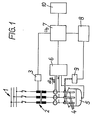
- the furnace system 1 shown in Fig. 1 has a transformer 2 with step switch 3 for regulating the voltage of the electrodes 4 across the bath 5.
- the measured variable di B / dt is measured as a measure of the electrode current and the voltage u and is output to a control panel 7, via which the tap changer 3 and the U B regulator 8, which are connected to it, can be controlled either by manual setting .
- the U B controller 8 controls the device for adjusting the electrode height 9.
- a current setpoint In addition to the detection of the actually flowing arc currents, the specification of a current setpoint is therefore also necessary. This can either be set manually in the control panel 7 or it is supplied by a process computer 10 during automatic operation. It does not matter whether the setting is made manually on the control panel or input via a process computer, since in both cases the setpoints are available in digital form and can therefore be processed directly by a computer.
- the three actual values of the arc currents are initially available in analog form on the part of the measuring device 6 and must first be digitized for processing. Because of the relatively long switching times of the tap changer, the three current measurement values can be queried one after the other, fed to an A / D converter and read into the computer serially. Finally, the computer must be informed whether balancing is desired at the present time or not. Therefore, a sufficiently large data capacity exceeded 'portable between computer and tap changer must be.
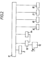
- Fig. 2 the interaction between the tap changer 3 and the computer 11 is outlined, which is shown in more detail in Fig. 3 with seventeen input or output lines.
- the current actual values run into an analog switch 12, which gives the measured values serially to a sample and hold module 13, where they are passed on to an A / D converter 14.
- This A / D converter 14 forwards the measured values to the computer 11, to which the predetermined target values are also supplied.
- the computer 11 uses a coding switch 15 to set the current setpoint value, a coding switch 16 for the minimum deviation between setpoint and actual values above which the step switch 3 is to be adjusted, and a coding switch 17 for the maximum permissible spread Between the highest and the lowest tap changer position (voltage difference) and a higher-level computer, which optionally specifies further program inputs for the computer 11, corresponding target values are supplied.
- the tasks for the system according to FIG. 2 are within such limits that they can be managed by a microcomputer 11 which essentially consists of memory modules, read-only memories (E-PROM) and working memories (RAM).
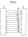
- Fig. 3 shows the connection of the computer 11 to the tap changer 3 with a transferable data width of 17 bits.
- a maximum of 32 tap changer positions can be regulated, for which information on the computer 11 requires a word length of 5 bits (connection 20).
- connection 21 is used with two bits for the phase number.
- Another 1 bit line 22 is required to signal that a valid tap changer position can be queried.
- Connections 23 to 31 are also provided, the data width of which is 1 bit for the purposes listed below:
- adjustment commands for the tap changer can be generated, ie the three options, not switching, switching one step up and switching one step lower, can be implemented. Accordingly, two control lines are provided for each tap changer, one for the adjustment command itself and one that indicates the direction in which adjustment is required.
- the respective position of the tap changer, or at least the upper and lower end position must be included for the following reason:
- the computer calculates in which phases and in which direction switched from the specified current setpoints and the determined current actual values must be achieved to achieve the desired goal.
- a control command may only be given if the corresponding switching operation can or may be carried out at all.
- a command to advance in the required direction is only permissible if the corresponding end position has not yet been reached or if the transformer is still permitting a further spreading of the voltage between two phases. This can be determined by the absence of the signal "end position" or by comparing the instantaneous position of the tap changer with the possible change in the respective direction or with the permissible spread.
- the computer After each adjustment of the tap changer in one, two or all three phases, the computer first has to work through the new situation again in order to derive the next commands from it. However, it cannot be assumed from the outset that the new position will be reported simultaneously with the completion of the entire switching operation. A line must therefore be planned as a precaution, which reports the completion of the switchover of the circuit breaker.
Landscapes
- Engineering & Computer Science (AREA)
- Power Engineering (AREA)
- Physics & Mathematics (AREA)
- Plasma & Fusion (AREA)
- Discharge Heating (AREA)
- Furnace Details (AREA)
- Vertical, Hearth, Or Arc Furnaces (AREA)
Priority Applications (1)
| Application Number | Priority Date | Filing Date | Title |
|---|---|---|---|
| AT86103145T ATE75576T1 (de) | 1985-04-03 | 1986-03-08 | Verfahren zur symmetrierung elektrischer groessen in drehstrom-lichtbogenoefen und vorrichtung zur durchfuehrung des verfahrens. |
Applications Claiming Priority (2)
| Application Number | Priority Date | Filing Date | Title |
|---|---|---|---|
| DE3512177 | 1985-04-03 | ||
| DE3512177A DE3512177C2 (de) | 1985-04-03 | 1985-04-03 | Verfahren zur Symmetrierung elektrischer Größen in Drehstrom-Lichtbogenöfen und Vorrichtung zur Durchführung des Verfahrens |
Publications (3)
| Publication Number | Publication Date |
|---|---|
| EP0197329A2 true EP0197329A2 (fr) | 1986-10-15 |
| EP0197329A3 EP0197329A3 (en) | 1988-06-22 |
| EP0197329B1 EP0197329B1 (fr) | 1992-04-29 |
Family
ID=6267204
Family Applications (1)
| Application Number | Title | Priority Date | Filing Date |
|---|---|---|---|
| EP86103145A Expired - Lifetime EP0197329B1 (fr) | 1985-04-03 | 1986-03-08 | Procédé pour équilibrer des grandeurs électriques dans des fours à arc à courant triphasé et dispositif pour exécuter le procédé |
Country Status (6)
| Country | Link |
|---|---|
| US (1) | US4663764A (fr) |
| EP (1) | EP0197329B1 (fr) |
| AT (1) | ATE75576T1 (fr) |
| CA (1) | CA1281353C (fr) |
| DE (1) | DE3512177C2 (fr) |
| ES (1) | ES8703706A1 (fr) |
Cited By (1)
| Publication number | Priority date | Publication date | Assignee | Title |
|---|---|---|---|---|
| EP0429774A1 (fr) * | 1989-11-30 | 1991-06-05 | DANIELI & C. OFFICINE MECCANICHE S.p.A. | Four électrique à arc à courant continu alimenté par du courant commandé et procédé d'alimentation d'un four à arc à courant continu en courant commandé |
Families Citing this family (15)
| Publication number | Priority date | Publication date | Assignee | Title |
|---|---|---|---|---|
| US5115447A (en) * | 1991-01-10 | 1992-05-19 | Ucar Carbon Technology Corporation | Arc furnace electrode control |
| CA2060006A1 (fr) * | 1991-02-08 | 1992-08-09 | Eduard Strebel | Procede et dispositif de commande des electrodes pour four a arc a courant continu |
| US5204872A (en) * | 1991-04-15 | 1993-04-20 | Milltech-Hoh, Inc. | Control system for electric arc furnace |
| US5331661A (en) * | 1992-02-27 | 1994-07-19 | Sandia Corporation | Method and apparatus for controlling electroslag remelting |
| SE501025C2 (sv) * | 1993-03-18 | 1994-10-24 | Asea Brown Boveri | Ugnsutrustning |
| DE4309640A1 (de) * | 1993-03-25 | 1994-09-29 | Abb Management Ag | Gleichstrom-Lichtbogenofenanlage |
| DE19711453C2 (de) * | 1997-03-19 | 1999-02-25 | Siemens Ag | Verfahren zur Regelung bzw. Steuerung eines Schmelzprozesses in einem Drehstrom-Lichtbogenofen |
| US6115404A (en) * | 1999-02-03 | 2000-09-05 | Sandia Corporation | Dynamic control of remelting processes |
| BRPI0515356B1 (pt) | 2004-09-01 | 2017-10-10 | Hatch Ltd. | "electric oven and method for operating an electric oven" |
| WO2006089315A1 (fr) * | 2005-02-20 | 2006-08-24 | Mintek | Commande de four a arc electrique |
| US20080056327A1 (en) * | 2006-08-30 | 2008-03-06 | Hatch Ltd. | Method and system for predictive electrode lowering in a furnace |
| ITMI20130396A1 (it) * | 2013-03-15 | 2014-09-16 | Danieli Off Mecc | Circuito elettrico per forno elettrico ad arco |
| DE102014206008A1 (de) * | 2014-03-31 | 2015-10-01 | Siemens Aktiengesellschaft | Vorrichtung und Verfahren zur dynamischen Einstellung eines Elektrolichtbogenofens |
| US10190821B2 (en) * | 2014-11-06 | 2019-01-29 | Showa Denko Carbon GmbH | Method for detection of the loss of an electric arc furnace measurement reference |
| CN108021783B (zh) * | 2017-11-08 | 2021-06-01 | 东北大学 | 双电极直流电熔镁炉操作电阻计算方法 |
Family Cites Families (5)
| Publication number | Priority date | Publication date | Assignee | Title |
|---|---|---|---|---|
| DE1159111B (de) * | 1961-05-31 | 1963-12-12 | Siemens Ag | Einrichtung zur Vermeidung der scharfen und toten Phase von Lichtbogenoefen |
| US3431344A (en) * | 1965-11-15 | 1969-03-04 | Westinghouse Electric Corp | Control system providing supply circuit impedance balance control for electric arc furnaces |
| US3493664A (en) * | 1968-03-08 | 1970-02-03 | Westinghouse Electric Corp | Control system for electric arc furnace |
| US3597518A (en) * | 1970-02-27 | 1971-08-03 | Robicon Corp | Electric arc furnace control |
| DE2440960B2 (de) * | 1974-08-27 | 1978-10-19 | Siemens Ag, 1000 Berlin Und 8000 Muenchen | Einrichtung zur Elektrodenregelung in einem Schmelzofen mit frei brennendem Lichtbogen |
-
1985
- 1985-04-03 DE DE3512177A patent/DE3512177C2/de not_active Expired - Fee Related
-
1986
- 1986-03-08 EP EP86103145A patent/EP0197329B1/fr not_active Expired - Lifetime
- 1986-03-08 AT AT86103145T patent/ATE75576T1/de not_active IP Right Cessation
- 1986-04-02 ES ES553635A patent/ES8703706A1/es not_active Expired
- 1986-04-02 CA CA000505684A patent/CA1281353C/fr not_active Expired - Lifetime
- 1986-04-03 US US06/847,732 patent/US4663764A/en not_active Expired - Fee Related
Cited By (2)
| Publication number | Priority date | Publication date | Assignee | Title |
|---|---|---|---|---|
| EP0429774A1 (fr) * | 1989-11-30 | 1991-06-05 | DANIELI & C. OFFICINE MECCANICHE S.p.A. | Four électrique à arc à courant continu alimenté par du courant commandé et procédé d'alimentation d'un four à arc à courant continu en courant commandé |
| US5239554A (en) * | 1989-11-30 | 1993-08-24 | Danieli & C. Officine Meccanichi Spa | Direct-arc electric furnace fed with controlled current and method to feed a direct-arc furnace with controlled current |
Also Published As
| Publication number | Publication date |
|---|---|
| DE3512177C2 (de) | 1997-01-16 |
| ATE75576T1 (de) | 1992-05-15 |
| ES8703706A1 (es) | 1987-02-16 |
| ES553635A0 (es) | 1987-02-16 |
| CA1281353C (fr) | 1991-03-12 |
| EP0197329B1 (fr) | 1992-04-29 |
| EP0197329A3 (en) | 1988-06-22 |
| US4663764A (en) | 1987-05-05 |
| DE3512177A1 (de) | 1986-10-09 |
Similar Documents
| Publication | Publication Date | Title |
|---|---|---|
| EP0197329B1 (fr) | Procédé pour équilibrer des grandeurs électriques dans des fours à arc à courant triphasé et dispositif pour exécuter le procédé | |
| EP0030637B1 (fr) | Dispositif de régulation des électrodes d'un four à arc | |
| DE69017884T2 (de) | Vorrichtung zur Steuerung des Blindwiderstands einer Starkstromleitung. | |
| DE69201573T2 (de) | Elektrodensteuerung für einen elektrischen Lichtbogenofen. | |
| EP0703652B1 (fr) | Méthode et appareil pour une allocation variable d'un convertiseur en fonctionemment avec au moins une charge | |
| EP0199936B1 (fr) | Procédé et dispositif pour la régulation de fours à arcs | |
| DE3608704A1 (de) | Spannungsspitzen freier festkoerperschalter und einrichtung zur automatischen leistungsfaktor-korrektur | |
| DE2827875A1 (de) | Mehrphasen-lichtbogenofen und verfahren zu dessen regelung | |
| DE19623540C1 (de) | Verfahren zur Stabilisierung eines Wechselstromnetzes gegen Blindleistungsschwankungen und Blindleistungskompensationseinrichtung | |
| EP3235091B1 (fr) | Procédé de fonctionnement en parallèle sélectif pour appareils de mesure/commande | |
| EP0103133B1 (fr) | Dispositif de réglage pour convertisseurs de courant | |
| EP0571643B1 (fr) | Procédé et dispositif de commande symétrique d'une installation de compensation série | |
| EP2389723B1 (fr) | Méthode pour le contrôle parallèle des transformateurs avec des changeurs de prise | |
| DE4415727C2 (de) | Verfahren zur Regelung des Schmelzprozesses in einem Drehstrom-Lichtbogenofen | |
| DE2731014C3 (de) | Einrichtung zur Regelung eines Drehstrom-Lichtbogenofens | |
| EP0417533B1 (fr) | Méthode et procédé de soudage | |
| EP3804118A1 (fr) | Fonctionnement optimisé d'une machine à entraînements multiples | |
| EP3447602B1 (fr) | Procédé et dispositif de commande de réglage de la tension d'un système de transformateur | |
| DE4216946A1 (de) | Dreiphasenumrichter zur symmetrischen Speisung einer dreiphasigen Last und Verfahren zu seinem Betrieb | |
| CH644721A5 (de) | Verfahren zur anpassung der betriebsparametern einer regelanordnung fuer die gleichspannung einer wechselrichterstation. | |
| EP3024137B1 (fr) | Entraînement linéaire doté d'un amortissement des vibrations adapté à la commande | |
| DE683433C (de) | Einrichtung zur selbsttaetigen Regelung der Energieuebertragung zwischen Wechselstromnetzen oder zwischen Gleich- und Wechselstromnetzen | |
| EP3753082B1 (fr) | Circuit électrique de compensation de puissance réactive | |
| DE909220C (de) | Anordnung zur Regelung technisch-physikalischer Betriebsgroessen | |
| DE4236080B4 (de) | Verfahren zum Betreiben eines Lichtbogenofens |
Legal Events
| Date | Code | Title | Description |
|---|---|---|---|
| PUAI | Public reference made under article 153(3) epc to a published international application that has entered the european phase |
Free format text: ORIGINAL CODE: 0009012 |
|
| AK | Designated contracting states |
Kind code of ref document: A2 Designated state(s): AT FR GB SE |
|
| PUAL | Search report despatched |
Free format text: ORIGINAL CODE: 0009013 |
|
| AK | Designated contracting states |
Kind code of ref document: A3 Designated state(s): AT FR GB SE |
|
| 17P | Request for examination filed |
Effective date: 19881207 |
|
| RAP1 | Party data changed (applicant data changed or rights of an application transferred) |
Owner name: MANNESMANN AKTIENGESELLSCHAFT |
|
| 17Q | First examination report despatched |
Effective date: 19900713 |
|
| GRAA | (expected) grant |
Free format text: ORIGINAL CODE: 0009210 |
|
| AK | Designated contracting states |
Kind code of ref document: B1 Designated state(s): AT FR GB SE |
|
| REF | Corresponds to: |
Ref document number: 75576 Country of ref document: AT Date of ref document: 19920515 Kind code of ref document: T |
|
| ET | Fr: translation filed | ||
| GBT | Gb: translation of ep patent filed (gb section 77(6)(a)/1977) | ||
| PLBE | No opposition filed within time limit |
Free format text: ORIGINAL CODE: 0009261 |
|
| STAA | Information on the status of an ep patent application or granted ep patent |
Free format text: STATUS: NO OPPOSITION FILED WITHIN TIME LIMIT |
|
| 26N | No opposition filed | ||
| PGFP | Annual fee paid to national office [announced via postgrant information from national office to epo] |
Ref country code: SE Payment date: 19940223 Year of fee payment: 9 |
|
| EAL | Se: european patent in force in sweden |
Ref document number: 86103145.8 |
|
| PG25 | Lapsed in a contracting state [announced via postgrant information from national office to epo] |
Ref country code: SE Effective date: 19950309 |
|
| EUG | Se: european patent has lapsed |
Ref document number: 86103145.8 |
|
| REG | Reference to a national code |
Ref country code: GB Ref legal event code: IF02 |
|
| PGFP | Annual fee paid to national office [announced via postgrant information from national office to epo] |
Ref country code: GB Payment date: 20020222 Year of fee payment: 17 |
|
| PGFP | Annual fee paid to national office [announced via postgrant information from national office to epo] |
Ref country code: AT Payment date: 20020307 Year of fee payment: 17 |
|
| PGFP | Annual fee paid to national office [announced via postgrant information from national office to epo] |
Ref country code: FR Payment date: 20020315 Year of fee payment: 17 |
|
| PG25 | Lapsed in a contracting state [announced via postgrant information from national office to epo] |
Ref country code: GB Free format text: LAPSE BECAUSE OF NON-PAYMENT OF DUE FEES Effective date: 20030308 Ref country code: AT Free format text: LAPSE BECAUSE OF NON-PAYMENT OF DUE FEES Effective date: 20030308 |
|
| GBPC | Gb: european patent ceased through non-payment of renewal fee |
Effective date: 20030308 |
|
| PG25 | Lapsed in a contracting state [announced via postgrant information from national office to epo] |
Ref country code: FR Free format text: LAPSE BECAUSE OF NON-PAYMENT OF DUE FEES Effective date: 20031127 |
|
| REG | Reference to a national code |
Ref country code: FR Ref legal event code: ST |