EP0197357A2 - Elektromagnetisch arbeitende Stelleinrichtung - Google Patents
Elektromagnetisch arbeitende Stelleinrichtung Download PDFInfo
- Publication number
- EP0197357A2 EP0197357A2 EP86103469A EP86103469A EP0197357A2 EP 0197357 A2 EP0197357 A2 EP 0197357A2 EP 86103469 A EP86103469 A EP 86103469A EP 86103469 A EP86103469 A EP 86103469A EP 0197357 A2 EP0197357 A2 EP 0197357A2
- Authority
- EP
- European Patent Office
- Prior art keywords
- abutment
- shaft
- shaped
- switching
- sleeve
- Prior art date
- Legal status (The legal status is an assumption and is not a legal conclusion. Google has not performed a legal analysis and makes no representation as to the accuracy of the status listed.)
- Granted
Links
Images
Classifications
-
- F—MECHANICAL ENGINEERING; LIGHTING; HEATING; WEAPONS; BLASTING
- F01—MACHINES OR ENGINES IN GENERAL; ENGINE PLANTS IN GENERAL; STEAM ENGINES
- F01L—CYCLICALLY OPERATING VALVES FOR MACHINES OR ENGINES
- F01L9/00—Valve-gear or valve arrangements actuated non-mechanically
- F01L9/20—Valve-gear or valve arrangements actuated non-mechanically by electric means
Definitions
- the invention relates to an electromagnetic actuating device according to the preamble of claim 1.
- Such an actuating device is known from DE-OS 30 24 109.
- the device described there has a single shaft, which is connected to the valve plate of an internal combustion engine and carries at its other end an anchor plate which can be moved back and forth between two magnets.
- An actuating magnet is provided in order to lead the equilibrium point of the spring system into an operating position at the start of operation, for this purpose an abutment for the base point of the spring system must be displaced. It is important that, insofar as the shaft is guided through the abutment, no canting occurs during the movement of the abutment, so that the shaft is guided with as little friction as possible after the abutment has reached the working position.
- the object of the invention is to provide a generic device in which malfunctions caused by tilting of the abutment during the movement from the rest position to the operating position are avoided.
- the abutment has a sleeve-shaped receptacle for the shaft-shaped attachment, with the aid of this sleeve-shaped receptacle, the abutment is accordingly Bearing guided along the shaft and can reach its exact working position.
- the abutment has bevels which cooperate with corresponding bevels in the working position, so that self-centering takes place.
- the invention further relates to a method for starting up the actuating device according to the invention. It is provided that an anchor plate connected to the control element runs in a guide, and during start-up the anchor plate and the sleeve-shaped receptacle for the shaft-shaped attachment ensure that the abutment is shifted into the intended working position.
- the sleeve-shaped extension now serves to guide the shaft and thus to guide the anchor plate in order to enable the anchor plate to work in a precisely aligned manner.
- the core of the method according to the invention is thus characterized in that first the anchor plate with the shaft guides the abutment and its sleeve. After the centering, the abutment and the sleeve now serve to guide the shaft with the anchor plate.
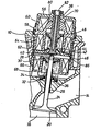
- Reference number 10 shows the cylinder head of the engine block of an internal combustion engine.
- the cylinder chamber 16 is vented through an outlet valve, which opens an outlet channel 14 when the valve plate 20 opens.
- the valve is controlled by * an electromagnetic actuator.
- a stem 24 leads from the valve plate 20 out of the cylinder head 10 out, which slides in the cylinder head in a sleeve 26.
- the end of the valve stem 24 is designated by the reference numeral 28, there it has a support on which a stamp head 40 to be described later strikes.
- a ring 30 is flanged circumferentially, which serves as an abutment for a spring system, which is composed of a large coil spring 32 and a small coil spring 34.
- the two coil springs 32 and 34 run coaxially into one another, the opposite base 36 is a support in the cylinder head.
- the valve stem 24 can be moved in the slide bearing 26 against the force of the spring system 32 and 34, the valve plate 20 then lifts from its seat and opens the outlet channel 14.
- valve stem 24 The axial extension to the valve stem 24 forms a stem 38 of a control element, which has a punch head 40 at its lower end for contact with the valve stem 26.
- annular anchor plate 46 which consists of ferromagnetic material, adjoins the shaft 38 of the control element.
- a spring system consisting of a large coil spring 42 and a small coil spring 44 rests on the anchor plate, which likewise run coaxially with one another and coaxially with the shaft 38 of the control element.
- This spring system 42 and 44 is formed by a support 48, which will be discussed later.
- a magnetic core 68 which is U-shaped in cross section, is arranged in a ring, the axis of the ring coincides with the axis of the valve stem 24.
- a coil 66 Inside the magnetic core 6ß is a coil 66, which is U-shaped magnetic core 68 in cross section Opened towards anchor plate 46.
- the stem 38 of the control is similar Lich formed magnetic core 66 which carries a coil 62 in its interior.
- the anchor plate 46 moves, depending on the Errequnq of the magnet 62 or 66, from an abutment on the magnetic core 64 to a contact with the magnetic core 68 and back.
- an actuating magnet which consists of a magnetic core 58 and a coil 60.
- a ferromagnetic element 56 is attracted, which is connected to a sleeve 70.
- the magnetic core 58 has a bevel on its working surface which defines a type of conical jacket, since the magnetic core 58 surrounds the shaft 38 of the control element in a ring.
- the ferromagnetic element 50 is likewise provided with a bevel 80, so that when it is attracted by the magnetic core 58, its bevel 80 comes exactly onto the bevel of the magnetic core 58 and thus centers itself in its attracted position.
- a sleeve-shaped receptacle 70 is connected to the ferromagnetic element 56, in which the shaft 38 of the control element is guided.
- the sleeve-shaped receptacle 70 forms a bore 82 in which the shaft 38 can slide back and forth.
- the ferromagnetic element 56 Due to the excitation of the coil 60, the ferromagnetic element 56 is attracted and centered with the aid of its bevel 80, so that the sleeve-shaped receptacle 70 moves downward and thus displaces the abutment 48 for the base point of the spring system 42 and 44.
- the switching magnet 64 is first excited, which moves the control element into its one switching position, preferably into the closed position.
- the control element 38 is thus in a defined position, and the subsequent excitation of the actuating magnet 60 transfers the point of equilibrium of the spring system 42 and 44 from an eccentric position between the magnets 62 and 66 to the center Position between the respective switching magnets, so that a symmetrical movement sequence of the control element 38 'can now take place between the two magnets 62 and 66.
- the armature plate 46 is held by the magnet 62 during the excitation of the actuating magnet 60 and is therefore relatively rigid.
- the shaft 38 of the control element fixed in this way thus moves in the bore 82 and therefore serves to guide the sleeve-shaped extension 70, so that the channel 82 is precisely aligned into the working position after the movement of the ferromagnetic element. At this time, the bevels 80 take over the exact centering.
- the bore 82 now serves for the exact guidance of the shaft 38 of the control element, the anchor plate 46 also sliding back and forth with its edge in a guide 86. Tilting of the anchor plate is now avoided by the sleeve-shaped receptacle 70, whereas previously the tilting of the sleeve-shaped receptacle 70 was prevented by the fixed anchor plate 46.
Landscapes
- Engineering & Computer Science (AREA)
- Mechanical Engineering (AREA)
- General Engineering & Computer Science (AREA)
- Valve Device For Special Equipments (AREA)
- Electromagnets (AREA)
- Magnetically Actuated Valves (AREA)
Abstract
Description
- Die Erfindung betrifft eine elektromagnetisch arbeitende Stelleinrichtung gemäß dem Oberbegriff des Anspruchs 1.
- Eine derartige Stelleinrichtung ist aus der DE-OS 30 24 109 be--kannt.
- Die dort beschriebene Vorrichtung besitzt einen einzigen Schaft, der mit dem Ventilteller einer Brennkraftmaschine verbunden ist und an seinem anderen Ende eine Ankerplatte trägt, die zwischen zwei Magneten hin- und herbewegbar ist. Ein Stellmagnet ist vorgesehen, um zu Beginn der Betriebsaufnahme den Gleichgewichtspunkt des Federsystems in eine Betriebsstellung zu führen, dazu muß ein Widerlager für den Fußpunkt des Federsystems verschoben werden. Dabei ist wichtig, daß, soweit durch das Widerlager auch der Schaft geführt wird, bei der Bewegung des Widerlagers keine Verkantung eintritt, damit der Schaft nach dem Erreichen der Arbeitsstellung des Widerlagers möglichst reibungsarm geführt wird.
- Aufgabe der Erfindung ist es, eine gattungsgemäße Vorrichtung zu schaffen, bei der Betriebsstörungen durch ein Verkanten des Widerlagers während der Bewegung von der Ruhestellung in die Betriebsstellung vermieden werden.
- Die Aufgabe wird gelöst durch den Hauptanspruch.
- Erfindungsgemäß ist vorgesehen, daß das Widerlager eine hülsenförmige Aufnahme für den schaftförmigen Ansatz besitzt, mit Hilfe dieser hülsenförmigen Aufnahme wird dementsprechend das Widerlager entlang des Schaftes geführt und kann seine genaue Arbeitsstellung erreichen.
- In einer bevorzugten Ausführungsform besitzt das Widerlager Schrägungen, die in der Arbeitsstellung mit entsprechenden Schrägungen zusammenarbeiten, so daß eine Eigenzentrierung erfolgt.
- Die Erfindung betrifft weiterhin ein Verfahren zur Inbetriebnahme der erfindungsgemäßen Stelleinrichtung. Dabei ist vorgesehen, daß eine mit dem Steuerelement verbundene Ankerplatte in einer Führung läuft und bei der Inbetriebnahme wird durch die Ankerplatte und die hülsenförmige Aufnahme für den schaftförmigen Ansatz sichergestellt, daß die Verschiebung des Widerlagers in die vorgesehene Arbeitsstellung durchgeführt wird.
- Ist dann aber das Widerlager in der vorgesehenen Arbeitsstellung, dient nunmehr der hülsenförmige Ansatz zur Führung des Schaftes und damit zur Führung der Ankerplatte, um ein genau ausgerichtetes Arbeiten der Ankerplatte zu ermöglichen.
- Das erfindungsgemäße Verfahren zeichnet sich also im Kern dadurch aus, daß zuerst die Ankerplatte mit dem Schaft das Widerlager und dessen Hülse führt. Anschließend nach der Zentrierung dient das Widerlager und die Hülse dazu, nunmehr den Schaft mit der Ankerplatte zu führen.
- Ein Ausführungsbeispiel der Erfindung ist in der Figur dargestellt. Mit dem Bezugszeichen 10 ist der Zylinderkopf des Motorblocks einer Brennkraftmaschine dargestellt. Der Zylinderraum 16 wird durch ein Auslaßventil entlüftet, das bei Öffnung des Ventiltellers 20 einen Auslaßkanal 14 freigibt. Das Ventil wird durch*eine elektromagnetisch arbeitende Stelleinrichtung gesteuert.
- Von denf Ventilteller 20 führt ein Schaft 24 aus dem Zylinderkopf 10 heraus, der im Zylinderkopf in einer Hülse 26 gleitet. Das Ende des Ventilschaftes 24 ist mit dem Bezugszeichen 28 bezeichnet, es hat dort eine Auflage, auf die ein später zu beschreibender Stempelkopf 40 auftrifft. An dem dem Ventilteller 20 gegenüberliegenden Ende des Ventilschaftes 2.4 ist umfangsmäßig ein Ring 30 angeflanscht, der als Widerlager für ein Federsystem dient, das aus einer großen Schraubenfeder 32 und einer kleinen Schraubenfeder 34 zusammengesetzt ist. Die beiden Schraubenfedern 32 und 34 laufen koaxial ineinandergefügt, der gegenüberliegende Fußpunkt 36 ist eine Auflage im Zylinderkopf. Der Ventilschaft 24 kann.in dem Gleitlager 26 gegen die Kraft des Federsystems 32 und 34 bewegt werden, der Ventilteller 20 hebt sich dann von seinem Sitz und öffnet den Auslaßkanal 14.
- Die axiale Verlängerung zu dem Ventilschaft 24 bildet ein Schaft 38 eines Steuerelementes, der an seinem unteren Ende zur Anlage mit dem Ventilschaft 26 einen Stempelkopf 40 besitzt. Im Bereich des Stempelkopfes 40 schließt sich an den Schaft 38 des Steuerelementes eine ringförmige Ankerplatte 46 an, die aus ferromagnetischem Material besteht. An der Ankerplatte liegt gleichzeitig ein Federsystem aus einer großen Schraubenfeder 42 und einer kleinen Schraubenfeder 44 an, die ebenfalls koaxial zueinander und koaxial mit dem Schaft 38 des Steuerelementes verlaufen.
- Der Fußpunkt dieses Federsystems 42 und 44 wird durch ein Auflager 48 gebildet, auf das im weiteren Verlauf noch einzugehen ist.
- Ein Magnetkern 68, der im Querschnitt U-förmig ist, ist ringförmig angeordnet, die Achse des Ringes fällt zusammen mit der Achse des Ventilschaftes 24. Im Innern des Magnetkernes 6ß befindet sich eine Spule 66, der im Querschnitt U-förmige Magnetkern 68 ist in Richtung zur Ankerplatte 46 geöffnet.
- Gleichermaßen ist der Schaft 38 des Steuerelementes von einem ähnlich ausgebildeten Magnetkern 66 umgeben, der in seinem Innern eine Spule 62 träqt. Die Ankerplatte 46 beweqt sich, je nach Errequnq des Magnetes 62 bzw. 66, von einer Anlaqe an den Magnetkern 64 zu einer Anlage an den Magnetkern 68 und zurück.
- Weiterhin ist ein Stellmaqnet vorgesehen, der aus einem Magnetkern 58 und einer Spule 60 besteht. Bei Erregung der Spule 60 wird ein ferromagnetisches Element 56 angezogen, das mit einer Hülse 70 verbunden ist. Der Magnetkern 58 besitzt an seiner Arbeitsfläche eine Schrägung, die eine Art Kegelmantel definiert, da der Magnetkern 58 den Schaft 38 des Steuerelementes ringförmig umgibt. Das ferromagnetische Element 50 ist gleichermaßen mit einer Schrägung 80 versehen, so daß es, wenn es von dem Magnetkern 58 angezogen wird, mit seiner Schräqung 80 genau auf die Schrägung des Magnetkernes 58 kommt und sich somit in seiner angezogenen Stellung selbst zentriert. Mit dem ferromagnetischen Element 56 ist eine hülsenförmige Aufnahme 70 verbunden, in der der Schaft 38 des Steuerelementes geführt ist. Die hülsenförmige Aufnahme 70 bildet eine Bohrung 82, in der der Schaft 38 hin- und hergleiten kann.
- Durch die Erregung der Spule 60 wird das ferromagnetische Element 56 angezogen und zentriert sich mit Hilfe seiner Schrägung 80, so daß sich die hülsenförmige Aufnahme 70 abwärts bewegt und damit das Widerlager 48 für den Fußpunkt des Federsystems 42 und 44 verschiebt.
- Zur Inbetriebnahme der erfindungsgemäßen Vorrichtung wird zuerst der Schaltmagnet 64 erregt, der das Steuerelement in seine eine Schaltposition, vorzugsweise in die Schließposition bewegt. Damit ist das Steuerelement 38 in einer definierten Stellung, und die anschließende Erregung des Stellmagneten 60 transferiert den Punkt der Gleichgewichtslage des Federsystems 42 und 44 von einer außermittigen Stellung zwischen den Magneten 62 und 66 in die mittige Stellung zwischen den jeweiligen Schaltmagneten, so daß nunmehr ein symmetrischer Bewegungsablauf des Steuerelementes 38'zwischen den beiden Magneten 62 und 66 stattfinden kann.
- Wesentlich dabei ist, daß während des Erregens des Stellmagneten 60 die Ankerplatte 46 festgehalten wird von dem Magneten 62 und somit verhältnismäßig starr ist. Der dermaßen fixierte Schaft 38 des Steuerelementes bewegt sich somit in der Bohrung 82 und dient deshalb zur Führung des hülsenförmigen Ansatzes 70, so daß der Kanal 82 nach vollendeter Bewegung des ferromagnetischen Elementes in die Arbeitsstellung genau ausgerichtet ist. Zu diesem Zeitpunkt übernehmen die Schrägungen 80 die exakte Zentrierung.
- In den nun darauf folgenden Arbeitsspielen dient jetzt die Bohrung 82 zur exakten Führung des Schaftes 38 des Steuerelementes, wobei die Ankerplatte 46 außerdem mit ihrem Rand in einer Führung 86 hin- und hergleitet. Das Verkanten der Ankerplatte wird nunmehr durch die hülsenförmige Aufnahme 70 vermieden, während vorher zur Inbetriebnahme des Verkanten der hülsenförmigen Aufnahme 70 durch die fixierte Ankerplatte 46 verhindert wurde.
Claims (3)
Applications Claiming Priority (2)
| Application Number | Priority Date | Filing Date | Title |
|---|---|---|---|
| DE19853513107 DE3513107A1 (de) | 1985-04-12 | 1985-04-12 | Elektromagnetisch arbeitende stelleinrichtung |
| DE3513107 | 1985-04-12 |
Publications (3)
| Publication Number | Publication Date |
|---|---|
| EP0197357A2 true EP0197357A2 (de) | 1986-10-15 |
| EP0197357A3 EP0197357A3 (en) | 1987-05-27 |
| EP0197357B1 EP0197357B1 (de) | 1989-01-11 |
Family
ID=6267804
Family Applications (1)
| Application Number | Title | Priority Date | Filing Date |
|---|---|---|---|
| EP86103469A Expired EP0197357B1 (de) | 1985-04-12 | 1986-03-14 | Elektromagnetisch arbeitende Stelleinrichtung |
Country Status (6)
| Country | Link |
|---|---|
| US (1) | US4682574A (de) |
| EP (1) | EP0197357B1 (de) |
| JP (1) | JPH069170B2 (de) |
| CA (1) | CA1272085A (de) |
| DE (2) | DE3513107A1 (de) |
| ES (1) | ES296853Y (de) |
Cited By (4)
| Publication number | Priority date | Publication date | Assignee | Title |
|---|---|---|---|---|
| WO1990001614A1 (de) | 1988-08-09 | 1990-02-22 | Audi Ag | Elektromagnetisch betätigbare stellvorrichtung |
| EP0405189A1 (de) * | 1989-06-27 | 1991-01-02 | FEV Motorentechnik GmbH & Co. KG | Elektromagnetisch arbeitende Stelleinrichtung |
| EP0796981A1 (de) | 1996-03-23 | 1997-09-24 | Bayerische Motoren Werke Aktiengesellschaft, Patentabteilung AJ-3 | Elektromagnetische Betätigungsvorrichtung für Brennkraftmaschinen-Hubventile |
| US5813653A (en) * | 1994-12-21 | 1998-09-29 | Fev Motorentechnik Gmbh & Co. Kg | Electromagnetically controlled regulator |
Families Citing this family (31)
| Publication number | Priority date | Publication date | Assignee | Title |
|---|---|---|---|---|
| US4976227A (en) * | 1990-04-16 | 1990-12-11 | Draper David J | Internal combustion engine intake and exhaust valve control apparatus |
| US5074259A (en) * | 1990-05-09 | 1991-12-24 | Pavo Pusic | Electrically operated cylinder valve |
| CA2087392C (en) * | 1992-04-27 | 1998-10-27 | Russell J. Vanrens | Double solenoid valve actuator |
| US5329897A (en) * | 1993-06-01 | 1994-07-19 | Renaissance Motor Works Co. | Rotary valve with seal for internal combustion engine |
| US5622351A (en) * | 1994-05-31 | 1997-04-22 | Daewoo Electronics Co., Ltd. | Water-supply valve of a washing machine |
| US5636601A (en) * | 1994-06-15 | 1997-06-10 | Honda Giken Kogyo Kabushiki Kaisha | Energization control method, and electromagnetic control system in electromagnetic driving device |
| DE19607019A1 (de) * | 1996-02-24 | 1997-08-28 | Daimler Benz Ag | Vorrichtung zur elektromagnetischen Betätigung eines Gaswechselventiles für Verbrennungsmotoren |
| US5692463A (en) * | 1996-11-12 | 1997-12-02 | Ford Global Technologies, Inc. | Electromechanically actuated valve with multiple lifts |
| US5647311A (en) * | 1996-11-12 | 1997-07-15 | Ford Global Technologies, Inc. | Electromechanically actuated valve with multiple lifts and soft landing |
| US5730091A (en) * | 1996-11-12 | 1998-03-24 | Ford Global Technologies, Inc. | Soft landing electromechanically actuated engine valve |
| US5765513A (en) * | 1996-11-12 | 1998-06-16 | Ford Global Technologies, Inc. | Electromechanically actuated valve |
| US5645019A (en) * | 1996-11-12 | 1997-07-08 | Ford Global Technologies, Inc. | Electromechanically actuated valve with soft landing and consistent seating force |
| US5669364A (en) * | 1996-11-21 | 1997-09-23 | Siemens Electric Limited | Exhaust gas recirculation valve installation for a molded intake manifold |
| US5960776A (en) * | 1996-11-21 | 1999-10-05 | Siemens Canada Limited | Exhaust gas recirculation valve having a centered solenoid assembly and floating valve mechanism |
| JP3422212B2 (ja) * | 1997-04-04 | 2003-06-30 | トヨタ自動車株式会社 | 電磁弁を備えた内燃機関のシリンダヘッド構造 |
| DE19745522C2 (de) * | 1997-10-15 | 2001-03-22 | Daimler Chrysler Ag | Vorrichtung zur Betätigung eines Gaswechselventiles einer Hubkolbenbrennkraftmaschine |
| US6044813A (en) * | 1997-12-09 | 2000-04-04 | Siemens Automotive Corporation | Electromagnetic actuator with detached lower collar to align with cylinder head bore |
| DE19814321A1 (de) * | 1998-03-31 | 1999-10-14 | Daimler Chrysler Ag | Verfahren zur Kühlung von Aktoren zur elektromagnetischen Ventilsteuerung bei Brennkraftmaschinen |
| DE19825412C2 (de) * | 1998-06-06 | 2001-10-25 | Daimler Chrysler Ag | Vorrichtung zum Betätigen eines Gaswechselventils |
| DE19835402C1 (de) * | 1998-08-05 | 2000-02-10 | Meta Motoren Energietech | Elektromagnetisch arbeitende Vorrichtung zum Betätigen eines Ventils |
| US6009841A (en) * | 1998-08-10 | 2000-01-04 | Ford Global Technologies, Inc. | Internal combustion engine having hybrid cylinder valve actuation system |
| DE19837837C1 (de) * | 1998-08-20 | 2000-01-05 | Daimler Chrysler Ag | Vorrichtung zum Betätigen eines Gaswechselventils |
| DE19838929C2 (de) * | 1998-08-27 | 2003-01-30 | Daimler Chrysler Ag | Vorrichtung zum Betätigen eines Gaswechselventils mit einem elektromagnetischen Aktuator |
| DE19900953C2 (de) * | 1999-01-13 | 2000-11-16 | Daimler Chrysler Ag | Vorrichtung zum Betätigen eines Gaswechselventils |
| ATE296944T1 (de) * | 1999-03-31 | 2005-06-15 | Fev Motorentech Gmbh | Gaswechselventilanordnung mit elektromagnetischem aktuator |
| DE19922423A1 (de) * | 1999-05-14 | 2000-11-30 | Siemens Ag | Elektromechanischer Stellantrieb |
| DE10005247C1 (de) | 2000-02-05 | 2001-02-15 | Daimler Chrysler Ag | Vorrichtung zum Betätigen eines Gaswechselventils einer Brennkraftmaschine |
| US20050076866A1 (en) * | 2003-10-14 | 2005-04-14 | Hopper Mark L. | Electromechanical valve actuator |
| JP2006336525A (ja) * | 2005-06-01 | 2006-12-14 | Toyota Motor Corp | 電磁駆動弁 |
| JP5472809B2 (ja) * | 2010-03-16 | 2014-04-16 | Ntn株式会社 | 動弁装置におけるラッシュアジャスタ |
| US10693358B2 (en) | 2017-02-03 | 2020-06-23 | Hamilton Sundstrand Corporation | Reciprocating electromagnetic actuator with flux-balanced armature and stationary cores |
Family Cites Families (5)
| Publication number | Priority date | Publication date | Assignee | Title |
|---|---|---|---|---|
| GB1391955A (en) * | 1972-07-12 | 1975-04-23 | British Leyland Austin Morris | Actuating internal combustion engine poppet valves |
| DE3024109A1 (de) * | 1980-06-27 | 1982-01-21 | Pischinger, Franz, Prof. Dipl.-Ing. Dr.Techn., 5100 Aachen | Elektromagnetisch arbeitende stelleinrichtung |
| DE3307070C2 (de) * | 1983-03-01 | 1985-11-28 | FEV Forschungsgesellschaft für Energietechnik und Verbrennungsmotoren mbH, 5100 Aachen | Stelleinrichtung für ein zwischen zwei Endstellungen verstellbares Schaltelement |
| DE3307683C1 (de) * | 1983-03-04 | 1984-07-26 | Klöckner, Wolfgang, Dr., 8033 Krailling | Verfahren zum Aktivieren einer elektromagnetisch arbeitenden Stelleinrichtung sowie Vorrichtung zum Durchfuehren des Verfahrens |
| SU1121469A1 (ru) * | 1983-03-28 | 1984-10-30 | Московский Ордена Ленина И Ордена Трудового Красного Знамени Институт Инженеров Железнодорожного Транспорта | Исполнительный узел электромагнитного привода клапанов газораспределени двигател внутреннего сгорани |
-
1985
- 1985-04-12 DE DE19853513107 patent/DE3513107A1/de active Granted
-
1986
- 1986-03-14 DE DE8686103469T patent/DE3661756D1/de not_active Expired
- 1986-03-14 EP EP86103469A patent/EP0197357B1/de not_active Expired
- 1986-04-09 ES ES1986296853U patent/ES296853Y/es not_active Expired
- 1986-04-10 JP JP61083959A patent/JPH069170B2/ja not_active Expired - Lifetime
- 1986-04-11 CA CA000506460A patent/CA1272085A/en not_active Expired - Lifetime
- 1986-04-11 US US06/850,937 patent/US4682574A/en not_active Expired - Lifetime
Cited By (7)
| Publication number | Priority date | Publication date | Assignee | Title |
|---|---|---|---|---|
| WO1990001614A1 (de) | 1988-08-09 | 1990-02-22 | Audi Ag | Elektromagnetisch betätigbare stellvorrichtung |
| EP0356713B1 (de) * | 1988-08-09 | 1992-05-06 | Audi Ag | Elektromagnetisch betätigbare Stellvorrichtung |
| US5199392A (en) * | 1988-08-09 | 1993-04-06 | Audi Ag | Electromagnetically operated adjusting device |
| EP0405189A1 (de) * | 1989-06-27 | 1991-01-02 | FEV Motorentechnik GmbH & Co. KG | Elektromagnetisch arbeitende Stelleinrichtung |
| US5813653A (en) * | 1994-12-21 | 1998-09-29 | Fev Motorentechnik Gmbh & Co. Kg | Electromagnetically controlled regulator |
| EP1069285A2 (de) | 1994-12-21 | 2001-01-17 | FEV Motorentechnik GmbH | Elektromagnetisch betätigbare Stellvorrichtung zur Betätigung eines Gaswechselventils mit Federschachtelung |
| EP0796981A1 (de) | 1996-03-23 | 1997-09-24 | Bayerische Motoren Werke Aktiengesellschaft, Patentabteilung AJ-3 | Elektromagnetische Betätigungsvorrichtung für Brennkraftmaschinen-Hubventile |
Also Published As
| Publication number | Publication date |
|---|---|
| US4682574A (en) | 1987-07-28 |
| JPS61240611A (ja) | 1986-10-25 |
| EP0197357A3 (en) | 1987-05-27 |
| CA1272085A (en) | 1990-07-31 |
| DE3661756D1 (en) | 1989-02-16 |
| DE3513107C2 (de) | 1989-06-08 |
| ES296853U (es) | 1988-02-01 |
| JPH069170B2 (ja) | 1994-02-02 |
| DE3513107A1 (de) | 1986-10-16 |
| ES296853Y (es) | 1988-09-16 |
| EP0197357B1 (de) | 1989-01-11 |
Similar Documents
| Publication | Publication Date | Title |
|---|---|---|
| EP0197357A2 (de) | Elektromagnetisch arbeitende Stelleinrichtung | |
| DE69509622T2 (de) | Elektromagnetventil für Bewässersteuerungseinheiten | |
| DE3513109C2 (de) | ||
| WO1994008831A1 (de) | Magnetventil | |
| DE3513106C2 (de) | ||
| DE69522951T2 (de) | Einrichtung zum bolzenschweissen | |
| DE3205953C2 (de) | Magnetventil zum Steuern eines abwechselnd in der einen und in der Gegenrichtung fließenden Mediumstroms | |
| DE60116564T2 (de) | Kraftstoffeinspritzventil | |
| DE10004961B4 (de) | Brennstoffeinspritzventil und Verfahren zu dessen Betrieb | |
| DE4339948A1 (de) | Kraftstoffeinspritzpumpe | |
| DE19849014A1 (de) | Treibstoffeinspritzvorrichtung | |
| DE3722344C2 (de) | 3/2-Mehrwegemagnetventil | |
| DE2647072A1 (de) | Elektromagnetventil | |
| DE3137761A1 (de) | Kraftstoff-einspritzduese fuer brennkraftmaschinen | |
| EP2516905B1 (de) | Elektromagnetventil | |
| DE3233759C2 (de) | Vorrichtung zum schrittweisen Vorbewegen einer Welle in axialer Richtung | |
| DE19712293A1 (de) | Elektromagnetisch arbeitende Stelleinrichtung | |
| DE3214845C2 (de) | ||
| DE3016543A1 (de) | Kraftstoffeinspritzanlage | |
| DE19908102C1 (de) | Ventil mit variablem Ventilquerschnitt | |
| DE2361591A1 (de) | Schieberventil zur steuerung des arbeitsdrucks eines arbeitsmediums | |
| DE2946632A1 (de) | Einspritzpumpen-ventil-vorrichtung zur kraftstoffzufuhr in die brennkammer einer brennkraftmaschine | |
| DE4022395C2 (de) | Proportionalmagnetventil und Verfahren zur Montage eines solchen Proportionalmagnetventiles | |
| DE3705514A1 (de) | Solenoidventil | |
| DE19632552C1 (de) | Einstellvorrichtung für den magnetischen Widerstand eines Magnetkreises in einem Magnetventil |
Legal Events
| Date | Code | Title | Description |
|---|---|---|---|
| PUAI | Public reference made under article 153(3) epc to a published international application that has entered the european phase |
Free format text: ORIGINAL CODE: 0009012 |
|
| AK | Designated contracting states |
Kind code of ref document: A2 Designated state(s): BE DE FR GB IT NL SE |
|
| PUAL | Search report despatched |
Free format text: ORIGINAL CODE: 0009013 |
|
| AK | Designated contracting states |
Kind code of ref document: A3 Designated state(s): BE DE FR GB IT NL SE |
|
| 17P | Request for examination filed |
Effective date: 19870423 |
|
| 17Q | First examination report despatched |
Effective date: 19871105 |
|
| ITF | It: translation for a ep patent filed | ||
| GRAA | (expected) grant |
Free format text: ORIGINAL CODE: 0009210 |
|
| AK | Designated contracting states |
Kind code of ref document: B1 Designated state(s): BE DE FR GB IT NL SE |
|
| GBT | Gb: translation of ep patent filed (gb section 77(6)(a)/1977) | ||
| REF | Corresponds to: |
Ref document number: 3661756 Country of ref document: DE Date of ref document: 19890216 |
|
| ET | Fr: translation filed | ||
| PLBE | No opposition filed within time limit |
Free format text: ORIGINAL CODE: 0009261 |
|
| STAA | Information on the status of an ep patent application or granted ep patent |
Free format text: STATUS: NO OPPOSITION FILED WITHIN TIME LIMIT |
|
| 26N | No opposition filed | ||
| NLS | Nl: assignments of ep-patents |
Owner name: AUDI AG TE INGOLSTADT, BONDSREPUBLIEK DUITSLAND. |
|
| ITPR | It: changes in ownership of a european patent |
Owner name: CESSIONE;AUDI AG |
|
| REG | Reference to a national code |
Ref country code: FR Ref legal event code: TP |
|
| REG | Reference to a national code |
Ref country code: GB Ref legal event code: 732 |
|
| ITTA | It: last paid annual fee | ||
| PGFP | Annual fee paid to national office [announced via postgrant information from national office to epo] |
Ref country code: DE Payment date: 19910405 Year of fee payment: 6 |
|
| PG25 | Lapsed in a contracting state [announced via postgrant information from national office to epo] |
Ref country code: DE Effective date: 19921201 |
|
| EAL | Se: european patent in force in sweden |
Ref document number: 86103469.2 |
|
| REG | Reference to a national code |
Ref country code: GB Ref legal event code: IF02 |
|
| PGFP | Annual fee paid to national office [announced via postgrant information from national office to epo] |
Ref country code: GB Payment date: 20050308 Year of fee payment: 20 |
|
| PGFP | Annual fee paid to national office [announced via postgrant information from national office to epo] |
Ref country code: SE Payment date: 20050316 Year of fee payment: 20 Ref country code: FR Payment date: 20050316 Year of fee payment: 20 |
|
| PGFP | Annual fee paid to national office [announced via postgrant information from national office to epo] |
Ref country code: BE Payment date: 20050318 Year of fee payment: 20 |
|
| PGFP | Annual fee paid to national office [announced via postgrant information from national office to epo] |
Ref country code: IT Payment date: 20050321 Year of fee payment: 20 |
|
| PGFP | Annual fee paid to national office [announced via postgrant information from national office to epo] |
Ref country code: NL Payment date: 20050322 Year of fee payment: 20 |
|
| PG25 | Lapsed in a contracting state [announced via postgrant information from national office to epo] |
Ref country code: GB Free format text: LAPSE BECAUSE OF EXPIRATION OF PROTECTION Effective date: 20060313 |
|
| PG25 | Lapsed in a contracting state [announced via postgrant information from national office to epo] |
Ref country code: NL Free format text: LAPSE BECAUSE OF EXPIRATION OF PROTECTION Effective date: 20060314 |
|
| REG | Reference to a national code |
Ref country code: GB Ref legal event code: PE20 |
|
| NLV7 | Nl: ceased due to reaching the maximum lifetime of a patent |
Effective date: 20060314 |
|
| EUG | Se: european patent has lapsed | ||
| BE20 | Be: patent expired |
Owner name: *AUDI A.G. Effective date: 20060314 |