EP0197384B1 - Verfahren zur Herstellung von Borstenwaren - Google Patents
Verfahren zur Herstellung von Borstenwaren Download PDFInfo
- Publication number
- EP0197384B1 EP0197384B1 EP86103779A EP86103779A EP0197384B1 EP 0197384 B1 EP0197384 B1 EP 0197384B1 EP 86103779 A EP86103779 A EP 86103779A EP 86103779 A EP86103779 A EP 86103779A EP 0197384 B1 EP0197384 B1 EP 0197384B1
- Authority
- EP
- European Patent Office
- Prior art keywords
- bristles
- thickened portion
- bristle
- process according
- channel
- Prior art date
- Legal status (The legal status is an assumption and is not a legal conclusion. Google has not performed a legal analysis and makes no representation as to the accuracy of the status listed.)
- Expired
Links
Images
Classifications
-
- B—PERFORMING OPERATIONS; TRANSPORTING
- B29—WORKING OF PLASTICS; WORKING OF SUBSTANCES IN A PLASTIC STATE IN GENERAL
- B29C—SHAPING OR JOINING OF PLASTICS; SHAPING OF MATERIAL IN A PLASTIC STATE, NOT OTHERWISE PROVIDED FOR; AFTER-TREATMENT OF THE SHAPED PRODUCTS, e.g. REPAIRING
- B29C65/00—Joining or sealing of preformed parts, e.g. welding of plastics materials; Apparatus therefor
- B29C65/02—Joining or sealing of preformed parts, e.g. welding of plastics materials; Apparatus therefor by heating, with or without pressure
-
- A—HUMAN NECESSITIES
- A46—BRUSHWARE
- A46B—BRUSHES
- A46B3/00—Brushes characterised by the way in which the bristles are fixed or joined in or on the brush body or carrier
- A46B3/06—Brushes characterised by the way in which the bristles are fixed or joined in or on the brush body or carrier by welding together bristles made of metal wires or plastic materials
-
- A—HUMAN NECESSITIES
- A46—BRUSHWARE
- A46D—MANUFACTURE OF BRUSHES
- A46D3/00—Preparing, i.e. Manufacturing brush bodies
- A46D3/005—Preparing, i.e. Manufacturing brush bodies by moulding or casting a body around bristles or tufts of bristles
-
- B—PERFORMING OPERATIONS; TRANSPORTING
- B29—WORKING OF PLASTICS; WORKING OF SUBSTANCES IN A PLASTIC STATE IN GENERAL
- B29C—SHAPING OR JOINING OF PLASTICS; SHAPING OF MATERIAL IN A PLASTIC STATE, NOT OTHERWISE PROVIDED FOR; AFTER-TREATMENT OF THE SHAPED PRODUCTS, e.g. REPAIRING
- B29C45/00—Injection moulding, i.e. forcing the required volume of moulding material through a nozzle into a closed mould; Apparatus therefor
- B29C45/14—Injection moulding, i.e. forcing the required volume of moulding material through a nozzle into a closed mould; Apparatus therefor incorporating preformed parts or layers, e.g. injection moulding around inserts or for coating articles
- B29C45/14336—Coating a portion of the article, e.g. the edge of the article
- B29C45/14385—Coating a portion of a bundle of inserts, e.g. making brushes
-
- B—PERFORMING OPERATIONS; TRANSPORTING
- B29—WORKING OF PLASTICS; WORKING OF SUBSTANCES IN A PLASTIC STATE IN GENERAL
- B29C—SHAPING OR JOINING OF PLASTICS; SHAPING OF MATERIAL IN A PLASTIC STATE, NOT OTHERWISE PROVIDED FOR; AFTER-TREATMENT OF THE SHAPED PRODUCTS, e.g. REPAIRING
- B29C66/00—General aspects of processes or apparatus for joining preformed parts
- B29C66/01—General aspects dealing with the joint area or with the area to be joined
- B29C66/05—Particular design of joint configurations
- B29C66/10—Particular design of joint configurations particular design of the joint cross-sections
- B29C66/13—Single flanged joints; Fin-type joints; Single hem joints; Edge joints; Interpenetrating fingered joints; Other specific particular designs of joint cross-sections not provided for in groups B29C66/11 - B29C66/12
- B29C66/137—Beaded-edge joints or bead seals
-
- B—PERFORMING OPERATIONS; TRANSPORTING
- B29—WORKING OF PLASTICS; WORKING OF SUBSTANCES IN A PLASTIC STATE IN GENERAL
- B29C—SHAPING OR JOINING OF PLASTICS; SHAPING OF MATERIAL IN A PLASTIC STATE, NOT OTHERWISE PROVIDED FOR; AFTER-TREATMENT OF THE SHAPED PRODUCTS, e.g. REPAIRING
- B29C66/00—General aspects of processes or apparatus for joining preformed parts
- B29C66/50—General aspects of joining tubular articles; General aspects of joining long products, i.e. bars or profiled elements; General aspects of joining single elements to tubular articles, hollow articles or bars; General aspects of joining several hollow-preforms to form hollow or tubular articles
- B29C66/51—Joining tubular articles, profiled elements or bars; Joining single elements to tubular articles, hollow articles or bars; Joining several hollow-preforms to form hollow or tubular articles
- B29C66/52—Joining tubular articles, bars or profiled elements
- B29C66/522—Joining tubular articles
-
- B—PERFORMING OPERATIONS; TRANSPORTING
- B29—WORKING OF PLASTICS; WORKING OF SUBSTANCES IN A PLASTIC STATE IN GENERAL
- B29C—SHAPING OR JOINING OF PLASTICS; SHAPING OF MATERIAL IN A PLASTIC STATE, NOT OTHERWISE PROVIDED FOR; AFTER-TREATMENT OF THE SHAPED PRODUCTS, e.g. REPAIRING
- B29C66/00—General aspects of processes or apparatus for joining preformed parts
- B29C66/69—General aspects of joining filaments
-
- B—PERFORMING OPERATIONS; TRANSPORTING
- B29—WORKING OF PLASTICS; WORKING OF SUBSTANCES IN A PLASTIC STATE IN GENERAL
- B29C—SHAPING OR JOINING OF PLASTICS; SHAPING OF MATERIAL IN A PLASTIC STATE, NOT OTHERWISE PROVIDED FOR; AFTER-TREATMENT OF THE SHAPED PRODUCTS, e.g. REPAIRING
- B29C67/00—Shaping techniques not covered by groups B29C39/00 - B29C65/00, B29C70/00 or B29C73/00
- B29C67/0044—Shaping techniques not covered by groups B29C39/00 - B29C65/00, B29C70/00 or B29C73/00 for shaping edges or extremities
-
- B—PERFORMING OPERATIONS; TRANSPORTING
- B29—WORKING OF PLASTICS; WORKING OF SUBSTANCES IN A PLASTIC STATE IN GENERAL
- B29C—SHAPING OR JOINING OF PLASTICS; SHAPING OF MATERIAL IN A PLASTIC STATE, NOT OTHERWISE PROVIDED FOR; AFTER-TREATMENT OF THE SHAPED PRODUCTS, e.g. REPAIRING
- B29C65/00—Joining or sealing of preformed parts, e.g. welding of plastics materials; Apparatus therefor
- B29C65/02—Joining or sealing of preformed parts, e.g. welding of plastics materials; Apparatus therefor by heating, with or without pressure
- B29C65/10—Joining or sealing of preformed parts, e.g. welding of plastics materials; Apparatus therefor by heating, with or without pressure using hot gases (e.g. combustion gases) or flames coming in contact with at least one of the parts to be joined
-
- B—PERFORMING OPERATIONS; TRANSPORTING
- B29—WORKING OF PLASTICS; WORKING OF SUBSTANCES IN A PLASTIC STATE IN GENERAL
- B29C—SHAPING OR JOINING OF PLASTICS; SHAPING OF MATERIAL IN A PLASTIC STATE, NOT OTHERWISE PROVIDED FOR; AFTER-TREATMENT OF THE SHAPED PRODUCTS, e.g. REPAIRING
- B29C65/00—Joining or sealing of preformed parts, e.g. welding of plastics materials; Apparatus therefor
- B29C65/02—Joining or sealing of preformed parts, e.g. welding of plastics materials; Apparatus therefor by heating, with or without pressure
- B29C65/14—Joining or sealing of preformed parts, e.g. welding of plastics materials; Apparatus therefor by heating, with or without pressure using wave energy, i.e. electromagnetic radiation, or particle radiation
-
- B—PERFORMING OPERATIONS; TRANSPORTING
- B29—WORKING OF PLASTICS; WORKING OF SUBSTANCES IN A PLASTIC STATE IN GENERAL
- B29C—SHAPING OR JOINING OF PLASTICS; SHAPING OF MATERIAL IN A PLASTIC STATE, NOT OTHERWISE PROVIDED FOR; AFTER-TREATMENT OF THE SHAPED PRODUCTS, e.g. REPAIRING
- B29C65/00—Joining or sealing of preformed parts, e.g. welding of plastics materials; Apparatus therefor
- B29C65/02—Joining or sealing of preformed parts, e.g. welding of plastics materials; Apparatus therefor by heating, with or without pressure
- B29C65/18—Joining or sealing of preformed parts, e.g. welding of plastics materials; Apparatus therefor by heating, with or without pressure using heated tools
-
- B—PERFORMING OPERATIONS; TRANSPORTING
- B29—WORKING OF PLASTICS; WORKING OF SUBSTANCES IN A PLASTIC STATE IN GENERAL
- B29C—SHAPING OR JOINING OF PLASTICS; SHAPING OF MATERIAL IN A PLASTIC STATE, NOT OTHERWISE PROVIDED FOR; AFTER-TREATMENT OF THE SHAPED PRODUCTS, e.g. REPAIRING
- B29C66/00—General aspects of processes or apparatus for joining preformed parts
- B29C66/70—General aspects of processes or apparatus for joining preformed parts characterised by the composition, physical properties or the structure of the material of the parts to be joined; Joining with non-plastics material
- B29C66/72—General aspects of processes or apparatus for joining preformed parts characterised by the composition, physical properties or the structure of the material of the parts to be joined; Joining with non-plastics material characterised by the structure of the material of the parts to be joined
- B29C66/727—General aspects of processes or apparatus for joining preformed parts characterised by the composition, physical properties or the structure of the material of the parts to be joined; Joining with non-plastics material characterised by the structure of the material of the parts to be joined being porous, e.g. foam
-
- B—PERFORMING OPERATIONS; TRANSPORTING
- B29—WORKING OF PLASTICS; WORKING OF SUBSTANCES IN A PLASTIC STATE IN GENERAL
- B29C—SHAPING OR JOINING OF PLASTICS; SHAPING OF MATERIAL IN A PLASTIC STATE, NOT OTHERWISE PROVIDED FOR; AFTER-TREATMENT OF THE SHAPED PRODUCTS, e.g. REPAIRING
- B29C66/00—General aspects of processes or apparatus for joining preformed parts
- B29C66/70—General aspects of processes or apparatus for joining preformed parts characterised by the composition, physical properties or the structure of the material of the parts to be joined; Joining with non-plastics material
- B29C66/73—General aspects of processes or apparatus for joining preformed parts characterised by the composition, physical properties or the structure of the material of the parts to be joined; Joining with non-plastics material characterised by the intensive physical properties of the material of the parts to be joined, by the optical properties of the material of the parts to be joined, by the extensive physical properties of the parts to be joined, by the state of the material of the parts to be joined or by the material of the parts to be joined being a thermoplastic or a thermoset
- B29C66/731—General aspects of processes or apparatus for joining preformed parts characterised by the composition, physical properties or the structure of the material of the parts to be joined; Joining with non-plastics material characterised by the intensive physical properties of the material of the parts to be joined, by the optical properties of the material of the parts to be joined, by the extensive physical properties of the parts to be joined, by the state of the material of the parts to be joined or by the material of the parts to be joined being a thermoplastic or a thermoset characterised by the intensive physical properties of the material of the parts to be joined
- B29C66/7311—Thermal properties
- B29C66/73115—Melting point
- B29C66/73116—Melting point of different melting point, i.e. the melting point of one of the parts to be joined being different from the melting point of the other part
Definitions
- the invention relates to a method for producing bristle goods, consisting of a bristle carrier made of pourable and foamable material and plastic bristles anchored therein, in that the bristles - individual bristles or bristle strands - are introduced through channels into a mold for the bristle carrier, at their shape end is thermally melted to form a thickening and then the shape is filled with the bristle carrier material.
- the conventional technique in the manufacture of bristle goods is to bundle the bristles, if necessary from the endless strand, to combine them and cut them to length, and then mechanically each bundle, possibly with the aid of putty - or adhesives to mechanically fasten in preformed holes in the bristle holder.
- the manufacturing process thus essentially consists of three stages, namely manufacturing the bundle of bristles, manufacturing the bristle carrier and connecting the two to one another.
- the bristle carriers are generally manufactured using the injection molding process, so that this can also be used when carrying out the aforementioned processes. Problems have arisen here, however, because the liquid material injected into the mold penetrates between the bristles and between them and the channels guiding them and, after hardening, leads to an undesirably irregular bristle-side end face on the bristle carrier.
- the bristle bundle also loses its elasticity in the area of its attachment to the bristle carrier; whereby - since this penetration does not occur uniformly - the different bristle bundles may show different bending behavior. Subsequent cleansing of the attachment points is not possible or is possible only with great effort.
- bristle carriers and bristles in a single injection molding process, the injection molding tool having a corresponding mold cavity for bristle carriers and bristles.
- the disadvantage here is that plastic bristles maintain their bending ability and their ability to straighten up, as well as their strength primarily by stretching the bristle material.
- a sprayed bristle does not have these properties.
- the bristles In the case of brushes which are injection-molded in one piece (DE-A-2 155 888, US-C-2 355 744), the bristles must therefore be stretched after the injection molding process. This requires complicated tools and corresponding approaches to the bristles to apply the tensile forces to the individual bristles. It is also practically impossible to stabilize bundles of bristles in this way. This method is completely unsuitable for fine bristles, for example toothbrushes, clothes brushes or the like. It also requires the same material for bristles and bristle carriers, the selection of which is primarily determined by the higher requirements placed on the bristle material.
- FR-A-1 133 844 a method for the production of bristle goods is known, wherein also at the fastening-side end of the bristles molded thickenings are pressed by means of heating elements onto the mouth opening of the channel leading them; however, the bristle carrier according to this patent partly consists of a frame and partly of a pourable material, so that the problem of the bristle carrier material escaping into the guide channels of the bristle strands does not arise.
- the invention has for its object to propose a method by means of which bristle products can be produced, the bristles and bristle carriers of any pourable or foamable, possibly also different materials, and also an absolutely clean finish is obtained at the approach of the bristle bundle on the bristle carrier .
- this object is achieved according to the invention in that the thickening on the bristles by means of tensile forces on the bristles for sealing contact with the mouth opening of the channel leading him.
- the invention is thus initially based on the known fact that the attachment of thickened portions at the bristle end leads to a perfect anchoring of the bristles in the bristle holder, in which the bristle bundle is held in the bristle holder by a combined force and form fit.
- the escape of the plastic material of the bristle carrier from the mold cavity into the guide channels is reliably avoided in that the mouth opening of each guide channel is closed by the thickening at the end of the bristles guided by it due to the tensile forces acting on them, between the thickening and the mold wall an undercut can remain, into which the plastic material of the bristle carrier can penetrate in order to additionally improve the desired anchoring.
- the thickening can be shaped in such a way that it only closes the opening edge in a linear manner, which results in a particularly good seal. This can easily be achieved in that the surface of the thickening facing the bristles is curved. Such a curvature usually occurs on its own when the bristle ends are thermally melted, in that the bristles shorten when they melt and the plastic material expands laterally into a spherical or pearly shape. This effect occurs automatically due to the stretching of the bristles. Instead, however, the contour of the thickening on the back can be designed such that it corresponds to a corresponding contour in the region of the mouth opening of the guide channel, for example in order to form longer sealing gaps or the like.
- the method according to the invention can be used with any combination of materials, in particular also with materials with different melting points, so that the bristle products produced in this way can be optimized in every respect with regard to the intended use, technological requirements and pricing.
- the thickening also ensures a perfect seal for individual bristles with a cross-sectional shape that deviates from the circular shape, as well as for profiled or hollow bristles, whether individually or in a bundle.
- the thickening can be brought into the sealing layer before the bristle carrier material is introduced into the mold. This can be done mechanically by pressing the compression against the mouth opening of the guide channel by means of tensile forces on the bristles; in the simplest way that, after the thickening has been formed, the bristles in the guide channel are withdrawn or the corresponding mold half is pushed towards the thickening until the thickening abuts the mouth opening.
- the thickening can also be shaped before or during the melting of the bristles and, if necessary, the contour of the opening edge of the guide channel can be shaped accordingly.
- the bristle carrier on the finished product has corresponding elevations on the bristle side, from each of which a bundle of bristles rises.
- the bristles can be inserted into the channel with a sleeve surrounding them and the thickening can be deformed against the end face of the sleeve.
- This embodiment also gives the possibility of guiding the sleeve tightly in the channel and sealingly pressing the thickening against the end face of the sleeve by tensile forces. The seal is therefore not made directly at the opening edge of the channel, but on the sleeve, which is pulled back together with the bristles into a position flush with the mold wall. Instead, however, it is also possible to pull the sleeve back into the channel after the thickening has been formed and to bring the thickening into its sealing position at the mouth opening of the channel.
- a plurality of bristles guided in adjacent channels can optionally also be deformed to form a coherent thickening by connecting the individual thickenings to one another via webs or the like.
- sufficient passage cross sections must remain for the material of the bristle carrier.
- the method according to the invention has the further significant advantage in all the described embodiments that the tie-in length of the bristles is limited to the dimension necessary for their perfect anchoring, with the result that on the one hand the bristle carrier only has to have the thickness required for its stability , so its thickness can be relatively small. This is particularly important for toothbrushes. Furthermore, the bristle length necessary for the integration is limited to a minimum, so that the generally more valuable bristle material can be used most economically for its actual purpose, namely the formation of the bristle.
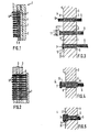
- a molding tool 1 e.g. an injection molding tool, recognizable, which consists of two parts 2, 3, of which the molded part 3 is stationary, the molded part 2, on the other hand, is displaceable for opening and closing the mold.
- the two molded parts 2, 3 enclose a molding space 4, the contour of which corresponds to the outer contour of a bristle carrier.
- a plurality of guide channels 5 parallel in the exemplary embodiment shown — in each of which a bristle strand 6 is guided, the end of which extends into the molding space 4.
- the bristle strands 6 can be fed from a coil as cut bundles of bristles or as continuous material.
- the ends of the bristle strands 6 are melted in such a way that a thickening 7 forms on each bristle strand.
- This can be done with mold 1 closed or open.
- hot air can be blown into the mold at a temperature which is sufficient to melt the bristle ends.
- the necessary softening temperature can be applied without contact or through contact heat. After or during the production of the thickenings 7, these are brought into the sealing position at the opening edge 8 of the guide channels.
- An undercut is present between the mold wall of the molded part 3 in the region of the mouth opening 8 of the guide channels 7 on the one hand and the rear side of the thickenings 7 facing this mold wall.
- the material for the bristle carrier is then introduced into the closed mold 1 in liquid to plastic form or else is produced within the mold, the material penetrating into the undercuts between the thickening 7 and the mold wall of the molded part 3.
- the mold is opened by moving the molded part 2 away (see FIG. 2), the bristle strands 6 being pulled through the guide channels 5 of the fixed molded part 3. Behind the molded part 3, the bristles can then be cut to length using a knife 9 in the case of an endless material. The bristle strands 6 are then pushed into the guide channels 5 until their ends are again in the mold cavity 4.
- Fig. 3 the essential process steps are shown on an enlarged scale.
- the bristle strand 6 is inserted into the guide channel 5 of the molded part 3 until its front end 10 passes through the opening 8 of the guide channel 5 and protrudes into the mold cavity 4.
- the end 10 of the bristle strand 6 is melted to form the thickening 7, a heater 11 1 being provided in the exemplary embodiment shown, which produces the necessary softening temperature without contact or through contact heat.
- the thickening 7 formed in this way then becomes the sealing layer on the mouth opening in the third stage 8 brought up by pulling on the bristle strand 6. This forms an undercut 13 between the back of the thickening 7 and the mold wall 12 of the molded part 3, into which the flowable material of the bristle carrier can then penetrate.
- the bristle strand is enclosed by a guide sleeve 14 which is guided tightly on the outside in the guide channel 5.
- the sleeve 14 has an optionally specially contoured end face 15, against which the thickening 7 is formed.
- the bristle strand 6 and the sleeve 14 are withdrawn before the molding space 4 is filled or the material contained therein is plasticized, the thickening 7 again reaching the sealing position at the opening edge 8 of the guide channel 5.
- the guide sleeve can either be withdrawn further than the bristle strand 6 or can be brought into a position in which it closes approximately flush with the mouth opening 8, so that the seal between the thickening 7 and the end face 15 of the sleeve 14 and also between the sleeve 14 and the guide channel.
- Fig. 5 shows an embodiment in which the thickening 7 is contoured in a certain way during or after the softening of the end of the bristle strand 6.
- the thickening is provided with a cylindrical extension 16 facing the bristles.
- the guide channel 5 is expanded in the region of its mouth opening 8 to a blind hole 17, the inside diameter and depth of which correspond to the shape of the extension 16.
- the thickening 7 formed in this way is forced into the blind hole 17 after it has been produced, so that, in addition to the sealing seat between the thickening 7 and the opening edge 8, there are also sealing gaps between the shoulder 16 and the blind hole 17, which serve primarily to reduce the pressure.
Landscapes
- Engineering & Computer Science (AREA)
- Mechanical Engineering (AREA)
- Manufacturing & Machinery (AREA)
- Brushes (AREA)
- Polishing Bodies And Polishing Tools (AREA)
- Mechanical Treatment Of Semiconductor (AREA)
- Crystals, And After-Treatments Of Crystals (AREA)
Description
- Die Erfindung betrifft ein Verfahren zur Herstellung von Borstenwaren, bestehend aus einem Borstenträger aus giess- und schäumfähigem Material und darin verankerten Borsten aus Kunststoff, indem die Borsten - Einzelborsten oder Borstenstränge - durch Kanäle in eine Form für den Borstenträger eingeführt, an ihrem in der Form befindlichen Ende zur Bildung einer Verdickung thermisch aufgeschmolzen und anschliessend die Form mit dem Borstenträgermaterial ausgefüllt wird.
- Die herkömmliche Technik bei der Herstellung von Borstenwaren, wie Bürsten, Besen, Matten oder dergleichen, besteht darin, die Borsten, ggf. vom Endlosstrang, zu bündeln, zusammenzufassen und auf Länge zu schneiden und daraufhin jedes Bündel mechanisch, ggf. unter Zuhilfenahme von Kitt- oder Klebemassen, in vorgeformten Löchern des Borstenträgers mechanisch zu befestigen. Das Herstellungsverfahren besteht also im wesentlichen aus drei Stufen, nämlich Herstellung des Borstenbündels, Herstellung des Borstenträgers und Verbinden der beiden miteinander. Um dieses aufwendige Verfahren zu vereinfachen, hat es seit Aufkommen der Kunststoffe nicht an Versuchen gefehlt, das thermoplastische Verhalten solcher Kunststoffe für den Herstellungsvorgang zu nutzen. So ist bereits vor vielen Jahrzehnten vorgeschlagen worden (DE-PS 355 645), die Borsten mit ihren Befestigungsenden in eine Hohlform für den Borstenträger einzuführen, die Hohlform mit einer unter Hitze plastifizierbaren Masse auszufüllen. Nach Erhärten dieser Masse sollen die Borsten in dem Borstenträger verankert sein. Bei dieser Methode findet keine oder nur eine sehr schlechte Bindung zwischen der glattwandigen Borste und dem Borstenträgermaterial statt, so dass die zwischen diesen Materialien vorhandenen Haftkräfte nicht ausreichen, um der Borste eine genügende Auszugsfestigkeit zu verleihen. Das Verfahren konnte sich deshalb nicht durchsetzen.
- Dieses Verfahren ist sehr viel später wieder aufgegriffen worden (DE-PS 895 140) und in Erkenntnis des vorgenannten Nachteils dahingehend modifiziert worden, dass für die Borsten und den Borstenträger gleiche Materialien, nämlich Polyamide oder Polyurethane verwendet werden, um bei der erhöhten Verarbeitungstemperatur eine Art thermischer Verschmelzung zwischen den beiden Materialien zu erhalten. Damit lassen sich aber nur Borstenwaren mit den werkstoffspezifischen Eigenschaften des jeweils verwendeten Materials herstellen, die wiederum nur bestimmten Anwendungszwecken gerecht werden. Auch handelt es sich bei den speziell vorgeschlagenen Materialien um relativ hochwertige Kunststoffe, die für viele Borstenwaren zu einer nicht vertretbaren Verteuerung führen.
- Die Borstenträger werden heute im allgemeinen im Spritzgiessverfahren hergestellt, so dass sich dieses auch bei der Ausführung der vorgenannten Verfahren anbietet. Hierbei haben sich jedoch Probleme deshalb ergeben, weil das in die Form eingespritzte flüssige Material zwischen die Borsten und zwischen diese und den sie führenden Kanälen eindringt und nach dem Erhärten zu einer unerwünscht unregelmässigen borstenseitigen Abschlussfläche am Borstenträger führt. Auch verliert das Borstenbündel im Bereich seines Ansatzes am Borstenträger seine Elastizität; wobei - da dieses Eindringen nicht gleichmässig geschieht - die verschiedenen Borstenbündel unter Umständen unterschiedliches Biegeverhalten zeigen. Eine anschliessende Versäuberung der Ansatzstellen ist nicht oder nur mit sehr grossem Aufwand möglich.
- Um die Einbindung der Borsten im Borstenträger zu verbessern, ist es weiterhin bekannt (DE-PS 845 933), die in den Formraum hineinreichenden Borstenenden aufzuschmelzen und ggf. zu verformen, so dass jedes Borstenbündel an seinem Ende eine seinen Durchmesser überschreitende Verdickung aufweist, die mit Abstand von der einen Formwandung angeordnet ist. Nach dem Umspritzen bzw. Umschäumen der Borstenenden sind diese kraft- und formschlüssig im Borstenträger verankert, so dass sich eine ausreichende Auszugsfestigkeit ergibt. Das Problem des Austretens des Borstenträgermaterials in die Führungskanäle der Borstenstränge ist damit allerdings nicht gelöst. Es hat deshalb nicht an Versuchen gefehlt (DE-OS 2 922 877), den Führungskanal für jedes Borstenbündel abzudichten, indem beispielsweise das Spritzgussmaterial zunächst mit geringem Druck an die eine Formwandung gespritzt und vorerhärtet und erst danach die grössere Menge des Spritzgussmaterials in die Form eingeführt wird. Dieses Verfahren ist dann, wenn man eine einwandfreie Abschlussfläche am Borstenträger erhalten will, ausserordentlich aufwendig. Weiterhin wird ein intensives Kühlen der Kanäle vorgeschlagen, was bei eng stehenden Borstenbündeln praktisch unmöglich ist. Auch der Vorschlag, in den Führungskanälen einen Gegendruck gegen den Spritzgussdruck zu erzeugen, ist nicht praktikabel, da dieser Gegendruck wiederum zu einer unregelmässigen Abschlussfläche am Borstenträger führt. Das gleiche gilt für ein vor dem Spritzgussvorgang erfolgendes Verschliessen der Mündungsöffnungen der Führungskanäle, die nach dem Druckabbau in der Form geöffnet werden, um anschliessend die Borstenstränge in das noch weichplastische Material einzudrücken. Hier wird in jedem Fall auch die Haftung zwischen Borsten und Borstenträgermaterial beeinträchtigt. Schliesslich schaffen auch mechanische Abdichtungen im Bereich der Führungskanäle, z.B. durch konusförmige Verengung der Mündungsöffnung oder dort angeordnete Dichtlippen keine Lösung des Problems, denn die Borsten lassen sich nicht so dicht packen, als dass nicht zwischen ihnen kapillarartige Zwischenräume verblieben. Dies gilt vor allem bei profilierten Borsten und hohlen Borsten. Die bei Borsten jeglicher Art auftretenden Schwankungen im Durchmesser und die meist von der Kreisform abweichende Querschnittsform führen in einem Bündel zu grösseren Lücken.
- Nach einem älteren Vorschlag (EP-A-0 149 996) sollen die am befestigungsseitigen Ende der Borsten angeformten Verdickungen mittels einer Anschlagplatte gegen den Öffnungsrand des Kanals gedrückt werden, um die Abdichtung zu besorgen. Da die Anschlagplatte aber vor dem Schliessen der Form entfernt werden muss, bleibt die Dichtkraft während des Spritzens oder Schäumens nicht erhalten. Das gleiche gilt für einen anderen älteren Vorschlag (EP-A-0 142 885), wonach der sich in der Form aufbauende Druck die Verdickung an den Öffnungsrand drücken soll. Dies würde aber einen schlagartig und isostatisch wirksamen Druckaufbau erfordern, was in der Praxis weder beim Spritzgiessen noch beim Schäumen der Fall ist.
- In Erkenntnis dieser Probleme geht eine andere Technologie dahin, Borstenträger und Borsten in einem einzigen Spritzgiessverfahren herzustellen, wobei das Spritzgusswerkzeug einen entsprechenden Formhohlraum für Borstenträger und Borsten aufweist. Hier ist der Nachteil, dass Kunststoffborsten ihre Biegefähigkeit und ihr Wiederaufrichtungsvermögen, wie auch ihre Festigkeit in erster Linie durch Verstrecken des Borstenmaterials erhalten. Diese Eigenschaften weist eine gespritzte Borste nicht auf. Es müssen deshalb bei einstückig gespritzten Bürsten (DE-A-2 155 888, US-C-2 355 744) die Borsten nach dem Spritzgiessvorgang verstreckt werden. Dies setzt komplizierte Werkzeuge und entsprechende Ansatzmöglichkeiten an den Borsten zum Aufbringen der Zugkräfte auf die einzelne Borste voraus. Auch lassen sich Borstenbündel auf diese Art praktisch nicht stabilisieren. Für feine Borsten, beispielweise Zahnbürsten, Kleiderbürsten od. dgl., ist dieses Verfahren völlig untauglich. Ebenso setzt es für Borste und Borstenträgre gleiches Material voraus, dessen Auswahl in erster Linie von den höheren Anforderungen, die an das Borstenmaterial gestellt werden, bestimmt wird.
- AusFR-A-1 133 844 ist ein Verfahren zur Herstellung von Borstenwaren bekannt, wobei auch am befestigungsseitigen Ende der Borsten angeformte Verdickungen mittels Heizelemente an die Mündungsöffnung des sie führenden Kanals gedrückt werden; jedoch besteht der Borstenträger gemäss dieser Patentschriftteilweise aus einem Rahmen und teilweise aus einem giessfähigen Material, so dass sich das Problem des Austretens des Borstenträger- materials in die Führungskanäle der Borstenstränge nicht stellt.
- Der Erfindung liegt die Aufgabe zugrunde, ein Verfahren vorzuschlagen, mit dessen Hilfe Borstenwaren hergestellt werden können, deren Borsten und Borstenträger aus beliebigen giess- oder schäumfähigen, gegebenenfalls auch verschiedenen Werkstoffen bestehen, und ferner am Ansatz der Borstenbündel am Borstenträger ein absolut sauberer Abschluss erhalten wird.
- Ausgehend von dem eingangs genannten Verfahren, bei dem die Borsten an ihrem in den Formraum reichenden Ende zur Bildung einer Verdickung thermisch aufgeschmolzen werden, wird diese Aufgabe erfindungsgemäss dadurch gelöst, dass die Verdickung an den Borsten mittels Zugkräften an den Borsten zur dichtenden Anlage an die Mündungsöffnung des ihn führenden Kanals gebracht wird.
- Die Erfindung geht also zunächst von der bekannten Tatsache aus, dass die Anbringung von Verdickungen am Borstenende zu einer einwandfreien Verankerung der Borsten im Borstenträger führt, in dem das Borstenbündel durch kombinierten Kraft-und Formschluss im Borstenträger gehalten wird. Das Austreten des plastischen Materials des Borstenträgers aus dem Formhohlraum in die Führungskanäle wird dadurch sicher vermieden, dass die Mündungsöffnung jedes Führungskanals durch die Verdickung an dem Ende der von ihm geführten Borsten aufgrund der an ihnen wirkenden Zugkräfte verschlossen wird, wobei zwischen der Verdickung und der Formwandung ein Hinterschnitt verbleiben kann, in den das plastische Material des Borstenträgers eindringen kann, um die gewünschte Verankerung zusätzlich zu verbessern. Die Verdickung kann so geformt sein, dass sie den Öffnungsrand nur linienförmig abschliesst, wodurch sich eine besonders gute Abdichtung ergibt. Dies lässt sich ohne weiteres dadurch erreichen, dass die den Borsten zugekehrte Fläche der Verdickung gekrümmt ist. Eine solche Krümmung stellt sich beim thermischen Aufschmelzen der Borstenenden in der Regel von allein ein, indem sich die Borsten beim Aufschmelzen verkürzen und das plastische Material sich seitlich zu einer kugel- bzw. perligen Form ausdehnt. Dieser Effekt stelltsich aufgrund der Verstreckung der Borsten automatisch ein. Stattdessen kann aber auch die Kontur der Verdickung an der Rückseite so ausgebildet sein, dass sie einer entsprechenden Kontur im Bereich der Mündungsöffnung des Führungskanals entspricht, um beispielsweise längere Dichtspalte oder dergleichen zu bilden.
- Das erfindungsgemässe Verfahren lässt sich bei jeder beliebigen Werkstoffkombination, insbesondere auch bei Werkstoffen mit unterschiedlichen Schmelzpunkten, anwenden, so dass sich die auf diese Weise hergestellten Borstenwaren hinsichtlich Anwendungszweck, technologischer Anforderungen und Preisgestaltung in jeder Hinsicht optimieren lassen. Auch sorgt die Verdickung für eine einwandfreie Abdichtung bei Einzelborsten mit von der Kreisform abweichender Querschnittsform, wie auch bei profilierten oder hohlen Borsten, ob einzeln oder im Bündel.
- Für die praktische Umsetzung des erfindungsgemässen Prinzips sind mehrere Ausführungen denkbar. So kann die Verdickung vor dem Einbringen des Borstenträgermaterials in die Form in die Dichtlage gebracht werden. Dies kann durch Andrücken der Verdichtung an die Mündungsöffnung des Führungskanals mittels Zugkräften an den Borsten in mechanischer Weise geschehen; in einfachster Weise dadurch, dass nach dem Anformen der Verdickung die Borsten im Führungskanal zurückgezogen oder aber die entsprechende Formhälfte an die Verdickung herangeschoben wird, bis die Verdickung an der Mündungsöffnung anliegt.
- Stattdessen ist es ferner möglich, die Verdickung anlässlich ihrer Erzeugung in die Dichtlage zu bringen, indem der Überstand des Borstenstrangs in dem Formhohlraum und der Aufschmelzvorgang so gewählt werden, dass die aufgeschmolzene Verdickung praktisch auf den Mündungsrand des Führungskanals aufschrumpft.
- Wie bereits angedeutet, kann die Verdickung vor oder während des Aufschmelzens der Borsten auch geformt und gegebenenfalls auch die Kontur des Öffnungsrandes des Führungskanals entsprechend geformt werden. So ist es beispielsweise möglich, an dem Führungskanal eine Mündungsöffnung grösseren Durchmessers, als für die Führung der Borsten notwendig, auszubilden und die Verdickung mit einem entsprechenden Ansatz zu versehen, der in der Dichtlage in die erweiterte Mündungsöffnung des Führungskanals hineingezogen wird. Damit ergeben sich neben einer möglichen Abdichtung der Verdickung am äusseren Öffnungsrand zusätzliche Dichtspalte zwischen der erweiterten Mündungsöffnung und dem angeformten Ansatz. In diesem Fall weist der Borstenträger am Fertigprodukt borstenseitig entsprechende Erhöhungen auf, aus denen jeweils ein Borstenbündel aufsteigt.
- Gemäss einem weiteren Merkmal der Erfindung können die Borsten mit einer sie umschliessenden Hülse in den Kanal eingeführt und die Verdickung gegen die Stirnseite der Hülse verformt werden. Mit dieser Ausbildung ist es insbesondere möglich, die Kontur an der der Formwandung zugekehrten Rückseite der Verdickung zu beeinflussen. Diese Ausführungsform gibtferner die Möglichkeit, die Hülse dicht in dem Kanal zu führen und die Verdickung dichtend an die Stirnseite der Hülse durch Zugkräfte anzudrücken. Die Abdichtung erfolgt somit nicht unmittelbar am Öffnungsrand des Kanals, sondern an der Hülse, wobei diese zusammen mit den Borsten in eine mit der Formwandung bündige Lage zurückgezogen wird. Stattdessen ist es aber auch möglich, die Hülse nach dem Anformen der Verdickung in den Kanal zurückzuziehen und die Verdickung in ihre Dichtlage an der Mündungsöffnung des Kanals zu bringen.
- In weiterer Abwandlung des Verfahrens können gegebenenfalls auch mehrere in benachbarten Kanälen geführte Borsten zu einer zusammenhängenden Verdickung verformt werden, indem die einzelnen Verdickungen über Stege oder dergleichen miteinander verbunden sind. Es müssen dabei allerdings ausreichende Durchtrittsquerschnitte für das Material des Borstenträgers verbleiben.
- Gegenüber den bekannten Verfahren hat das erfindungsgemässe Verfahren in allen beschriebenen Ausführungsformen den weiteren wesentlichen Vorteil, dass die Einbindungslänge der Borsten auf das für ihre einwandfreie Verankerung notwendige Mass beschränkt ist, mit der Folge, dass einerseits der Borstenträger nur die für seine Stabilität geforderte Dicke aufweisen muss, seine Dicke also relativ gering sein kann. Dies ist insbesondere bei Zahnbürsten von Bedeutung. Ferner wird die für die Einbindung notwendiger Borstenlänge auf ein Minimum eingegrenzt, so dass das im allgemeinen wertvollere Borstenmaterial am wirtschaftlichsten für seinen eigentlichen Zweck, nämlich die Bildung der Borste, genutzt werden kann.
- Nachstehend ist die Erfindung anhand vorrichtungstechnischer Ausführungsbeispiele, die in der Zeichnung wiedergegeben sind, beschrieben. In der Zeichnung zeigen:
- Fig. 1 einen Schnitt durch eine Spritzgiess- oder Schäumform nach dem Ausfüllen des Formhohlraums;
- Fig. 2 einen der Fig. 1 ähnlichen Schnitt nach dem Entformen des Borstenträgers;
- Fig. 3 eine schematische Darstellung der Verfahrensschritte;
- Fig. 4 einen der Fig. 3 ähnlichen Schnitt einer weiteren Ausführungsform und
- Fig. 5 eine weitere abgewandelte Ausführungsform im Schnitt.
- In Fig. 1 ist ein Formwerkzeug 1, z.B. ein Spritzgusswerkzeug, erkennbar, das aus zwei Teilen 2, 3 besteht, von denen das Formteil 3 ortsfest, das Formteil 2 demgegenüber zum Öffnen und Schliessen der Form verschiebbar ist. Die beiden Formteile 2, 3 schliessen einen Formraum 4 ein, dessen Kontur der Aussenkontur eines Borstenträgers entspricht. Auf dem aufspannseitigen Formteil 3 sind mehrere - beim dargestellten Ausführungsbeispiel parallele - Führungskanäle 5 angeordnet, in denen jeweils ein Borstenstrang 6 geführt ist, der mit seinem Ende in den Formraum 4 hineinragt. Die Borstenstränge 6 können als geschnittene Borstenbündel oder aber als Endlosmaterial von einer Spule zugeführt werden.
- Vor dem Ausfüllen des Formraums 4 mit dem Material des Borstenträgers werden die Enden der Borstenstränge 6 aufgeschmolzen, derart, dass sich an jedem Borstenstrang eine Verdickung 7 bildet. Dies kann bei geschlossener oder geöffneter Form 1 geschehen. Im Falle einer geschlossenen Form kann beispielsweise Heissluft mit einer Temperatur in die Form eingeblasen werden, die zum Aufschmelzen der Borstenenden ausreicht. Bei geöffneter Form kann die notwendige Erweichungstemperatur berührungslos oder durch Kontaktwärme aufgebracht werden. Nach oder während der Erzeugung der Verdickungen 7 werden diese in Dichtlage an den Öffnungsrand 8 der Führungskanäle gebracht. Zwischen der Formwandung des Formteils 3 im Bereich der Mündungsöffnung 8 der Führungskanäle 7 einerseits und der dieser Formwandung zugekehrten Rückseite der Verdickungen 7 ist ein Hinterschnitt vorhanden. In die geschlossene Form 1 wird dann das Material für den Borstenträger in flüssig bis plastischer Form eingebracht oder aber innerhalb der Form erzeugt, wobei das Material in die Hinterschnitte zwischen Verdickung 7 und Formwandung des Formteils 3 eindringt.
- Nach dem Erhärten des Borstenträger-Materials wird die Form durch Abrücken des Formteils 2 geöffnet, (siehe Fig. 2) wobei die Borstenstränge 6 durch die Führungskanäle 5 des ortsfesten Formteils 3 hindurchgezogen werden. Hinter dem Formteil 3 können dann die Borsten im Falle eines Endlosmaterials mittels eines Messers 9 auf Länge geschnitten werden. Daraufhin werden die Borstenstränge 6 in die Führungskanäle 5 nachgeschoben, bis sich ihre Enden wieder im Formhohlraum 4 befinden.
- In Fig. 3 sind die wesentlichen Verfahrensschritte in vergrössertem Massstab wiedergegeben. Der Borstenstrang 6 wird in den Führungskanal 5 des Formteils 3 soweit eingeführt, bis sein vorderes Ende 10 die Mündungsöffnung 8 des Führungskanals 5 passiert und in den Formhohlraum 4 hineinragt. In der zweiten Stufe wird das Ende 10 des Borstenstrangs 6 zu der Verdickung 7 aufgeschmolzen, wobei bei dem gezeigten Ausführungsbeispiel eine Heizung 11 1 vorgesehen ist, die berührungslos oder durch Kontaktwärme die notwendige Erweichungstemperatur herstellt. Die so gebildete Verdickung 7 wird dann in der dritten Stufe zur Dichtlage an die Mündungsöffnung 8 herangebracht durch Zug am Borstenstrang 6. Dabei bildet sich zwischen der Rückseite der Verdickung 7 und der Formwandung 12 des Formteils 3 ein Hinterschnitt 13, in den dann das fliessfähige Material des Borstenträgers eindringen kann.
- Bei der Ausführungsform gemäss Fig. 4 ist der Borstenstrang von einer Führungshülse 14 eingeschlossen, die aussenseitig dicht im Führungskanal 5 geführt wird. Die Hülse 14 weist eine gegebenenfalls speziell konturierte Stirnseite 15 auf, gegen die die Verdickung 7 ausgeformt wird. Vor dem Ausfüllen des Formraums 4 bzw. dem Plastifizieren des darin befindlichen Materials werden der Borstenstrang 6 und die Hülse 14 zurückgezogen, wobei die Verdickung 7 wiederum in die Dichtlage am Öffnungsrand 8 des Führungskanals 5 gelangt. Dabei kann die Führungshülse entweder weiter zurückgezogen werden als der Borstenstrang 6 oder aber in eine Lage gebracht werden, in dersie etwa bündig mitder Mündungsöffnung 8 abschliesst, so dass die Abdichtung zwischen der Verdickung 7 und der Stirnseite 15 der Hülse 14 sowie weiterhin zwischen der Hülse 14 und dem Führungskanal erfolgt.
- Fig. 5 zeigt ein Ausführungsbeispiel, bei dem die Verdickung 7 während oder nach dem Erweichen des Endes des Borstenstranges 6 in bestimmter Weise konturiert wird. In diesem Fall wird die Verdickung mit einem den Borsten zugekehrten zylindrischen Ansatz 16 versehen. In korrespondierender Weise ist der Führungskanal 5 im Bereich seiner Mündungsöffnung 8 zu einem Sackloch 17 erweitert, dessen Innendurchmesser und Tiefe der Form des Ansatzes 16 entspricht. Die solchermassen gebildete Verdickung 7 wird nach ihrer Erzeugung in das Sackloch 17 hineingedrängt, so dass neben dem Dichtsitz zwischen Verdickung 7 und Öffnungsrand 8 ferner Dichtspalte zwischen dem Ansatz 16 und dem Sackloch 17 entstehen, die vor allem dem Druckabbau dienen.
Claims (13)
Priority Applications (1)
| Application Number | Priority Date | Filing Date | Title |
|---|---|---|---|
| AT86103779T ATE36638T1 (de) | 1985-03-29 | 1986-03-20 | Verfahren zur herstellung von borstenwaren. |
Applications Claiming Priority (2)
| Application Number | Priority Date | Filing Date | Title |
|---|---|---|---|
| DE3511528 | 1985-03-29 | ||
| DE3511528A DE3511528C1 (de) | 1985-03-29 | 1985-03-29 | Verfahren zur Herstellung von Borstenwaren |
Publications (2)
| Publication Number | Publication Date |
|---|---|
| EP0197384A1 EP0197384A1 (de) | 1986-10-15 |
| EP0197384B1 true EP0197384B1 (de) | 1988-08-24 |
Family
ID=6266754
Family Applications (1)
| Application Number | Title | Priority Date | Filing Date |
|---|---|---|---|
| EP86103779A Expired EP0197384B1 (de) | 1985-03-29 | 1986-03-20 | Verfahren zur Herstellung von Borstenwaren |
Country Status (9)
| Country | Link |
|---|---|
| US (1) | US4892698A (de) |
| EP (1) | EP0197384B1 (de) |
| JP (1) | JP2601452B2 (de) |
| AT (1) | ATE36638T1 (de) |
| DD (1) | DD244062A5 (de) |
| DE (1) | DE3511528C1 (de) |
| DK (1) | DK159525C (de) |
| ES (1) | ES8702780A1 (de) |
| NO (1) | NO165623C (de) |
Families Citing this family (50)
| Publication number | Priority date | Publication date | Assignee | Title |
|---|---|---|---|---|
| JPS61140877U (de) * | 1985-02-20 | 1986-09-01 | ||
| DE3628722C5 (de) * | 1986-08-23 | 2005-04-14 | Coronet-Werke Gmbh | Zahnreinigungsgerät |
| DE3637750A1 (de) * | 1986-11-05 | 1988-05-11 | Zahoransky Anton Fa | Verfahren zum verbinden von borstenbuendeln mit einem buerstenkoerper od. dgl., damit hergestellter buerstenkoerper sowie buerstenherstellungsmaschine dafuer |
| DE3642124C2 (de) * | 1986-12-10 | 1995-11-23 | Coronet Werke Gmbh | Verfahren zur Herstellung von Borstenwaren und Vorrichtung zur Durchführung des Verfahrens |
| DE3705431A1 (de) * | 1987-02-20 | 1988-09-01 | Schlerf Coronet Werke | Fussmatte |
| JPS6430021U (de) * | 1987-08-19 | 1989-02-23 | ||
| JP2732875B2 (ja) * | 1988-02-03 | 1998-03-30 | コロネツト‐ヴエルケ ハインリツヒ シユレルフ ゲゼルシヤフト ミツト ベシユレンクテル ハフツング | 剛毛製品を製造する方法 |
| US5094789A (en) * | 1988-08-24 | 1992-03-10 | Odhner Oliver R | Method for eraser manufacture |
| DE3832520A1 (de) * | 1988-09-24 | 1990-04-05 | Schiffer Fa M & C | Verfahren und vorrichtung zum herstellen von buersten, insbesondere von buersten fuer hygienische beduerfnisse, wie zahnbuersten |
| DE69018070T2 (de) * | 1990-06-28 | 1995-08-10 | Boucherie Nv G B | Bürstenherstellungsmaschine. |
| US5224763A (en) * | 1991-12-30 | 1993-07-06 | The Procter & Gamble Company | Method of fastening bristle tufts to bristle carrier |
| EP0567672B1 (de) * | 1992-04-28 | 1995-09-06 | G.B. Boucherie, N.V. | Verfahren zum Herstellen von Zahnbürsten |
| DE4311186A1 (de) * | 1993-04-06 | 1994-10-13 | Schiffer Fa M & C | Verfahren und Vorrichtung zur Herstellung von Bürstenwaren |
| US5350219A (en) * | 1993-07-26 | 1994-09-27 | Acumen Co., Ltd | Toothbrush without metal gasket |
| GB2288140A (en) * | 1994-04-07 | 1995-10-11 | Boucherie Nv G B | A method of injection molding of brushes |
| DE4415886A1 (de) * | 1994-05-05 | 1995-11-09 | Coronet Werke Gmbh | Verfahren zur Herstellung von Borstenwaren im Wege des Spritzgießens |
| DE19506597A1 (de) * | 1995-02-27 | 1996-08-29 | Coronet Werke Gmbh | Borstenware sowie Verfahren und Vorrichtung zu ihrer Herstellung |
| DE29515391U1 (de) * | 1995-09-15 | 1996-02-29 | Hoeft, Bernd, Dipl.-Ing., 12555 Berlin | Vorrichtung zur Herstellung von Borstenwaren |
| US5895612A (en) * | 1996-01-11 | 1999-04-20 | Jason Incorporated | Method of making abrading tools |
| US6036277A (en) * | 1996-02-14 | 2000-03-14 | Coronet-Werke Gmbh | Method for the manufacture of brushware |
| US6029304A (en) | 1998-06-09 | 2000-02-29 | Colgate-Palmolive Company | Light interactive toothbrush |
| DE19853030A1 (de) | 1998-11-18 | 2000-05-25 | Coronet Werke Gmbh | Verfahren zur Herstellung von Borstenwaren und Vorrichtung zur Durchführung des Verfahrens |
| DE19900765A1 (de) * | 1999-01-12 | 2000-07-13 | Braun Gmbh | Vorrichtung zur Beseitigung von Plaques und zur Reinigung von Zahnzwischenräumen |
| DE59908270D1 (de) * | 1999-06-02 | 2004-02-12 | Schiffer Fa M & C | Verfahren und vorrichtung zur herstellung von bürsten |
| JP3467451B2 (ja) * | 1999-06-25 | 2003-11-17 | 株式会社呉竹 | 毛 束 |
| JP4255176B2 (ja) * | 1999-08-25 | 2009-04-15 | 三菱鉛筆株式会社 | 化粧具又は筆記具等のブラシ及びその製造方法 |
| US6260928B1 (en) * | 1999-12-15 | 2001-07-17 | Moll Industries, Inc. | Handle Configuration for brush production by fusion |
| DE19962188A1 (de) | 1999-12-22 | 2001-09-06 | Schiffer Fa M & C | Verfahren zur Herstellung eines Bürstenkopfes im Wege des Spritzgiessens |
| US6523907B1 (en) * | 2000-02-01 | 2003-02-25 | Moll Industries, Inc. | Apparatus and method for producing brushware by injection molding |
| US6553604B1 (en) | 2000-03-16 | 2003-04-29 | Gillette Canada Company | Toothbrush |
| GB0020021D0 (en) | 2000-08-16 | 2000-10-04 | Smithkline Beecham Gmbh & Co | Process |
| DE10123258A1 (de) * | 2001-05-12 | 2002-11-21 | Braun Gmbh | Zahnbürstenkopf |
| US20030094848A1 (en) * | 2001-11-20 | 2003-05-22 | Chih-Yuan Shia | Fused filament tuft and fused brush strip |
| KR100445838B1 (ko) * | 2002-04-04 | 2004-08-25 | 주식회사 엘지생활건강 | 앵커레스 칫솔 제조방법 |
| DE10244499A1 (de) * | 2002-09-25 | 2004-04-15 | Braun Gmbh | Borstenwaren und Verfahren zur Herstellung einer Borstenware |
| AR043336A1 (es) | 2003-01-20 | 2005-07-27 | Glaxosmithkline Consumer Healt | Cabeza de cepillo de dientes con cerdas triangulares y ondulantes |
| US20060272112A9 (en) * | 2003-03-14 | 2006-12-07 | The Gillette Company | Toothbrush |
| US20040177462A1 (en) * | 2003-03-14 | 2004-09-16 | The Gillette Company | Toothbrush head |
| US7941886B2 (en) | 2003-09-19 | 2011-05-17 | Braun Gmbh | Toothbrushes |
| US20050116035A1 (en) * | 2003-10-02 | 2005-06-02 | Preh-Werke Gmbh & Co. Kg | Card reader |
| JP4816037B2 (ja) | 2005-12-02 | 2011-11-16 | サンスター株式会社 | 歯ブラシ |
| DE102006011671A1 (de) * | 2006-03-14 | 2007-09-20 | Firma G.B. Boucherie N.V. | Verfahren und Vorrichtung zum Verschmelzen der axialen Enden von gebündelten Fasern aus thermoplastischem Kunststoff |
| DE102006012043A1 (de) * | 2006-03-16 | 2007-09-20 | Braun Gmbh | Nietverbindung auf Kunststoffbasis |
| DE102006026712A1 (de) * | 2006-06-08 | 2007-12-13 | M + C Schiffer Gmbh | Zahnbürste und Verfahren zu deren Herstellung |
| EP2436283B1 (de) * | 2010-09-29 | 2016-08-24 | Braun GmbH | Verfahren zur Herstellung eines Bürstenkopfs |
| EP2534973B1 (de) * | 2011-06-15 | 2015-04-08 | Braun GmbH | Verfahren und Werkzeug zur Herstellung eines Bürstenkopfs |
| EP2676572B1 (de) * | 2012-06-19 | 2018-07-04 | Braun GmbH | Träger für Reinigungselemente und Verfahren zur Verwendung solcher Träger bei der Produktion von Zahnbürstenköpfen |
| US20150097309A1 (en) | 2013-10-04 | 2015-04-09 | The Procter & Gamble Company | Process and apparatus for making tufted article |
| EP2886009B1 (de) * | 2013-12-18 | 2019-01-30 | The Gillette Company LLC | Vorrichtung zum verschmelzen der enden von thermoplastischen fäden und entsprechendes verfahren |
| EP3138437B1 (de) | 2015-09-03 | 2021-11-10 | Braun GmbH | Verfahren zum herstellen einer bürste |
Family Cites Families (19)
| Publication number | Priority date | Publication date | Assignee | Title |
|---|---|---|---|---|
| DE264652C (de) * | ||||
| DE355645C (de) * | 1919-01-09 | 1922-06-30 | Ernst Krause | Verfahren zur Herstellung von Buersten |
| DE895140C (de) * | 1941-06-05 | 1953-11-02 | Basf Ag | Verfahren zur Herstellung von Buersten und aehnlichen Erzeugnissen |
| US2355744A (en) * | 1942-05-07 | 1944-08-15 | Henry W Mckisson | Brush manufacture |
| US2643158A (en) * | 1947-06-25 | 1953-06-23 | Columbia Protektosite Co Inc | Method of making molded brushes |
| US2655409A (en) * | 1947-07-05 | 1953-10-13 | Columbia Protektosite Co Inc | Art of and apparatus for molding brushes |
| DE845933C (de) * | 1949-07-28 | 1953-06-11 | Maximilian Schiffer | Verfahren und Maschine zum Herstellen von Buersten, insbesondere von Zahnbuersten |
| FR1133844A (fr) * | 1955-04-08 | 1957-04-02 | Brosse & J Dupont Reunis | Procédé de fabrication de brosses en matières plastiques |
| FR1453829A (fr) * | 1965-03-05 | 1966-07-22 | Procédé de fabrication de brosses et analogues | |
| DE1532809A1 (de) * | 1966-01-11 | 1970-04-02 | M & C Schiffer Fa | Zahnbuerste |
| CH531406A (de) * | 1970-11-12 | 1972-12-15 | Haenggi Peter | Verfahren und Vorrichtung zum Herstellen von Bürsten oder Borstenträgern |
| US4106745A (en) * | 1973-05-07 | 1978-08-15 | Phillips Petroleum Company | Apparatus for attaching an insert in a mold |
| JPS5424349B2 (de) * | 1973-06-11 | 1979-08-20 | ||
| DE2922877A1 (de) * | 1979-06-06 | 1980-12-18 | Zahoransky Anton Fa | Verfahren zum herstellen von buersten sowie buerstenherstellungsmaschine zur durchfuehrung des verfahrens |
| IL57898A (en) * | 1979-07-26 | 1983-05-15 | Helioset Advanced Tech | Method for injection-molding of elements onto extruded units |
| CH645005A5 (fr) * | 1981-12-30 | 1984-09-14 | Sylvain Nahum | Brosse a dents. |
| US4635313A (en) * | 1983-11-16 | 1987-01-13 | North American Philips Corporation | Brush with self retaining bristles |
| DE3484093D1 (de) * | 1983-11-16 | 1991-03-14 | Philips Corp | Verfahren zur herstellung von buersten mit selbstbefestigung der borsten sowie nach diesem verfahren hergestellte buersten. |
| EP0149996A3 (de) * | 1984-01-10 | 1987-10-21 | Schlesinger GmbH & Co. Maschinenbau KG | Verfahren und Maschine zum Herstellen von Bürsten |
-
1985
- 1985-03-29 DE DE3511528A patent/DE3511528C1/de not_active Expired - Lifetime
-
1986
- 1986-03-20 EP EP86103779A patent/EP0197384B1/de not_active Expired
- 1986-03-20 AT AT86103779T patent/ATE36638T1/de not_active IP Right Cessation
- 1986-03-24 NO NO861169A patent/NO165623C/no unknown
- 1986-03-25 DK DK137886A patent/DK159525C/da not_active IP Right Cessation
- 1986-03-26 ES ES553490A patent/ES8702780A1/es not_active Expired
- 1986-03-27 DD DD86288442A patent/DD244062A5/de not_active IP Right Cessation
- 1986-03-28 US US06/845,342 patent/US4892698A/en not_active Expired - Lifetime
- 1986-03-28 JP JP61068897A patent/JP2601452B2/ja not_active Expired - Lifetime
Also Published As
| Publication number | Publication date |
|---|---|
| ES553490A0 (es) | 1987-01-16 |
| NO861169L (no) | 1986-09-30 |
| NO165623C (no) | 1991-03-13 |
| DK159525C (da) | 1991-04-02 |
| DE3511528C1 (de) | 1991-01-03 |
| ATE36638T1 (de) | 1988-09-15 |
| ES8702780A1 (es) | 1987-01-16 |
| DK137886D0 (da) | 1986-03-25 |
| DD244062A5 (de) | 1987-03-25 |
| NO165623B (no) | 1990-12-03 |
| DK159525B (da) | 1990-10-29 |
| JPS61268208A (ja) | 1986-11-27 |
| US4892698A (en) | 1990-01-09 |
| DK137886A (da) | 1986-09-30 |
| JP2601452B2 (ja) | 1997-04-16 |
| EP0197384A1 (de) | 1986-10-15 |
Similar Documents
| Publication | Publication Date | Title |
|---|---|---|
| DE3511528C1 (de) | Verfahren zur Herstellung von Borstenwaren | |
| EP0759711B1 (de) | Verfahren zur herstellung von borstenwaren im wege des spritzgiessens | |
| EP0150785B1 (de) | Verfahren zum Verbinden von Borsten mit einem Borstenträger | |
| DE10033256A1 (de) | Verfahren und Vorrichtung zur Herstellung von Borstenwaren sowie Borstenware | |
| DE10221869A1 (de) | Verfahren zur Herstellung einer Borstenstruktur an einem Träger | |
| EP2135526A1 (de) | Bürste, insbesondere Zahnbürste und Verfahren zu deren Herstellung | |
| EP2676781B1 (de) | Verfahren und Vorrichtung zur Herstellung einer einstückig mehrkomponentig spritzgegossenen Bürste | |
| DE4106465A1 (de) | Verfahren zum herstellen einer abdeckung, insbesondere einer modularen oder bausteinartigen abdeckung, eines luftsacks | |
| DE19858102A1 (de) | Bürstenkörper sowie Verfahren zum Herstellen eines Bürstenkörpers | |
| WO1989006920A1 (fr) | Procede pour fabriquer des soies | |
| EP0668140B1 (de) | Verfahren zur Herstellung von Zahnbürsten | |
| EP0326634B1 (de) | Verfahren zur Herstellung von Borstenwaren | |
| DE102006026712A1 (de) | Zahnbürste und Verfahren zu deren Herstellung | |
| DE3832520A1 (de) | Verfahren und vorrichtung zum herstellen von buersten, insbesondere von buersten fuer hygienische beduerfnisse, wie zahnbuersten | |
| WO1988003376A1 (fr) | Procede pour la fabrication d'articles a soies | |
| DE19518143C1 (de) | Verfahren und Vorrichtung zum Herstellen von dünnwandigen laminierten Formteilen | |
| DE3712962C2 (de) | Verfahren zur Herstellung von Borstenwaren | |
| DE4226390C2 (de) | Hohlkörper-Spritzgießverfahren | |
| EP1181144A1 (de) | Verfahren und vorrichtung zur herstellung von bürsten | |
| DE19958316C1 (de) | Verfahren und Vorrichtung zum Herstellen eines Kunststoffformteils, welches mehrere Felder umfaßt | |
| DE102009009034A1 (de) | Bürste, insbesondere Zahnbürste und Verfahren zu deren Herstellung | |
| EP1003632A1 (de) | Kunststoff-formteil sowie verfahren und vorrichtung zu dessen herstellung | |
| DE69300067T2 (de) | Verfahren zum Herstellen von Autospoilern. | |
| DE102004059066B4 (de) | Verfahren zur Herstellung eines heterogenen, insbesondere mehrfarbigen Flächengebildes, Werkzeug und Flächengebilde | |
| DE19513451A1 (de) | Verfahren zum Herstellen von Bürsten |
Legal Events
| Date | Code | Title | Description |
|---|---|---|---|
| PUAI | Public reference made under article 153(3) epc to a published international application that has entered the european phase |
Free format text: ORIGINAL CODE: 0009012 |
|
| AK | Designated contracting states |
Kind code of ref document: A1 Designated state(s): AT BE CH FR GB IT LI NL SE |
|
| 17P | Request for examination filed |
Effective date: 19861009 |
|
| 17Q | First examination report despatched |
Effective date: 19871218 |
|
| GRAA | (expected) grant |
Free format text: ORIGINAL CODE: 0009210 |
|
| AK | Designated contracting states |
Kind code of ref document: B1 Designated state(s): AT BE CH FR GB IT LI NL SE |
|
| REF | Corresponds to: |
Ref document number: 36638 Country of ref document: AT Date of ref document: 19880915 Kind code of ref document: T |
|
| ITF | It: translation for a ep patent filed | ||
| GBT | Gb: translation of ep patent filed (gb section 77(6)(a)/1977) | ||
| ET | Fr: translation filed | ||
| PLBE | No opposition filed within time limit |
Free format text: ORIGINAL CODE: 0009261 |
|
| STAA | Information on the status of an ep patent application or granted ep patent |
Free format text: STATUS: NO OPPOSITION FILED WITHIN TIME LIMIT |
|
| 26N | No opposition filed | ||
| ITTA | It: last paid annual fee | ||
| EAL | Se: european patent in force in sweden |
Ref document number: 86103779.4 |
|
| REG | Reference to a national code |
Ref country code: GB Ref legal event code: IF02 |
|
| PGFP | Annual fee paid to national office [announced via postgrant information from national office to epo] |
Ref country code: GB Payment date: 20030310 Year of fee payment: 18 |
|
| PGFP | Annual fee paid to national office [announced via postgrant information from national office to epo] |
Ref country code: AT Payment date: 20030314 Year of fee payment: 18 |
|
| PGFP | Annual fee paid to national office [announced via postgrant information from national office to epo] |
Ref country code: NL Payment date: 20030317 Year of fee payment: 18 |
|
| PGFP | Annual fee paid to national office [announced via postgrant information from national office to epo] |
Ref country code: SE Payment date: 20030318 Year of fee payment: 18 Ref country code: FR Payment date: 20030318 Year of fee payment: 18 |
|
| PGFP | Annual fee paid to national office [announced via postgrant information from national office to epo] |
Ref country code: BE Payment date: 20030326 Year of fee payment: 18 |
|
| PGFP | Annual fee paid to national office [announced via postgrant information from national office to epo] |
Ref country code: CH Payment date: 20030528 Year of fee payment: 18 |
|
| PG25 | Lapsed in a contracting state [announced via postgrant information from national office to epo] |
Ref country code: GB Free format text: LAPSE BECAUSE OF NON-PAYMENT OF DUE FEES Effective date: 20040320 Ref country code: AT Free format text: LAPSE BECAUSE OF NON-PAYMENT OF DUE FEES Effective date: 20040320 |
|
| PG25 | Lapsed in a contracting state [announced via postgrant information from national office to epo] |
Ref country code: SE Free format text: LAPSE BECAUSE OF NON-PAYMENT OF DUE FEES Effective date: 20040321 |
|
| PG25 | Lapsed in a contracting state [announced via postgrant information from national office to epo] |
Ref country code: LI Free format text: LAPSE BECAUSE OF NON-PAYMENT OF DUE FEES Effective date: 20040331 Ref country code: CH Free format text: LAPSE BECAUSE OF NON-PAYMENT OF DUE FEES Effective date: 20040331 Ref country code: BE Free format text: LAPSE BECAUSE OF NON-PAYMENT OF DUE FEES Effective date: 20040331 |
|
| BERE | Be: lapsed |
Owner name: *CORONET-WERKE HEINRICH SCHLERF G.M.B.H. Effective date: 20040331 |
|
| PG25 | Lapsed in a contracting state [announced via postgrant information from national office to epo] |
Ref country code: NL Free format text: LAPSE BECAUSE OF NON-PAYMENT OF DUE FEES Effective date: 20041001 |
|
| EUG | Se: european patent has lapsed | ||
| GBPC | Gb: european patent ceased through non-payment of renewal fee |
Effective date: 20040320 |
|
| REG | Reference to a national code |
Ref country code: CH Ref legal event code: PL |
|
| PG25 | Lapsed in a contracting state [announced via postgrant information from national office to epo] |
Ref country code: FR Free format text: LAPSE BECAUSE OF NON-PAYMENT OF DUE FEES Effective date: 20041130 |
|
| NLV4 | Nl: lapsed or anulled due to non-payment of the annual fee |
Effective date: 20041001 |
|
| REG | Reference to a national code |
Ref country code: FR Ref legal event code: ST |
|
| PG25 | Lapsed in a contracting state [announced via postgrant information from national office to epo] |
Ref country code: IT Free format text: LAPSE BECAUSE OF NON-PAYMENT OF DUE FEES;WARNING: LAPSES OF ITALIAN PATENTS WITH EFFECTIVE DATE BEFORE 2007 MAY HAVE OCCURRED AT ANY TIME BEFORE 2007. THE CORRECT EFFECTIVE DATE MAY BE DIFFERENT FROM THE ONE RECORDED. Effective date: 20050320 |