EP0197399A2 - Dispositif pour mélanger - Google Patents
Dispositif pour mélanger Download PDFInfo
- Publication number
- EP0197399A2 EP0197399A2 EP86103920A EP86103920A EP0197399A2 EP 0197399 A2 EP0197399 A2 EP 0197399A2 EP 86103920 A EP86103920 A EP 86103920A EP 86103920 A EP86103920 A EP 86103920A EP 0197399 A2 EP0197399 A2 EP 0197399A2
- Authority
- EP
- European Patent Office
- Prior art keywords
- container part
- mixing
- container
- mixing device
- pivot axis
- Prior art date
- Legal status (The legal status is an assumption and is not a legal conclusion. Google has not performed a legal analysis and makes no representation as to the accuracy of the status listed.)
- Granted
Links
Images
Classifications
-
- B—PERFORMING OPERATIONS; TRANSPORTING
- B01—PHYSICAL OR CHEMICAL PROCESSES OR APPARATUS IN GENERAL
- B01F—MIXING, e.g. DISSOLVING, EMULSIFYING OR DISPERSING
- B01F27/00—Mixers with rotary stirring devices in fixed receptacles; Kneaders
- B01F27/80—Mixers with rotary stirring devices in fixed receptacles; Kneaders with stirrers rotating about a substantially vertical axis
- B01F27/808—Mixers with rotary stirring devices in fixed receptacles; Kneaders with stirrers rotating about a substantially vertical axis with stirrers driven from the bottom of the receptacle
-
- B—PERFORMING OPERATIONS; TRANSPORTING
- B01—PHYSICAL OR CHEMICAL PROCESSES OR APPARATUS IN GENERAL
- B01F—MIXING, e.g. DISSOLVING, EMULSIFYING OR DISPERSING
- B01F33/00—Other mixers; Mixing plants; Combinations of mixers
- B01F33/35—Mixing after turning the mixing vessel upside down
-
- B—PERFORMING OPERATIONS; TRANSPORTING
- B01—PHYSICAL OR CHEMICAL PROCESSES OR APPARATUS IN GENERAL
- B01F—MIXING, e.g. DISSOLVING, EMULSIFYING OR DISPERSING
- B01F35/00—Accessories for mixers; Auxiliary operations or auxiliary devices; Parts or details of general application
- B01F35/30—Driving arrangements; Transmissions; Couplings; Brakes
- B01F35/32—Driving arrangements
- B01F35/321—Disposition of the drive
- B01F35/3213—Disposition of the drive at the lower side of the axis, e.g. driving the stirrer from the bottom of a receptacle
Definitions
- the invention relates to a mixing device according to the preamble of claim 1.
- a mixing device of the type required in the preamble of claim 1 is known from DE-B-21 10 047. It enables inexpensive mixing without the need for large vertical relative movements between the mixing container and the mixing tool in order to produce and cancel the mixing position.
- a lifting device is required in order to connect the first container part, which is designed to be transportable, to the second container part, which is pivotably mounted on the stationary holder. Furthermore, since the second container part with the drive motor for the agitator carried by it has to be pivoted, if necessary, even without the first container part or when the mixing container is not full, whereby a considerable torque must be applied by the drive motor arranged far outside the pivot axis, the pivot drive must known execution are undesirably large.
- the invention is therefore based on the object of designing a mixing device of the type required in the preamble of claim 1 in such a way that a lifting device for the transportable first container part can be dispensed with and the pivot drive for the mixing container can be dimensioned substantially smaller.
- the second container part can be raised and lowered with respect to the pivot axis by means of a lifting device according to the invention, a separate lifting device for the transportable first container part can be dispensed with.
- the second container part is lowered onto the latter and then raised in order to be pivoted into the mixed position.
- the second container part and the drive motor for the agitator carried by it can be raised and lowered with respect to the pivot axis, it is possible to shift the center of gravity of the pivotable parts before pivoting movement so that it coincides with the pivot axis.
- the second container part with the drive motor carried by it can also be pivoted with a low torque - if, for example, the second container part is to be pivoted without the first container part for cleaning purposes or if a pivoting movement of the complete, but not or only slightly filled mixing container is required.
- the required pivot drive can be dimensioned very small and inexpensive.
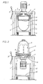
- a stationary holder 1 in which a pivot shaft 2 is pivotably mounted by means of a handle 3 (instead of the handle 3, a motorized pivoting device can of course also be provided).
- the first container part 5 is raised so far that it can be connected to the second container part 6 pivoted into the position according to FIG.
- the mixing container 4 can then be pivoted into the mixing position according to FIG. 2 by means of the swivel shaft 2, the second container part 6 now forming the bottom of the mixing container and an intensive mixing movement taking place inside the mixing container 4 by means of the agitator 8. After the mixing process has ended, the mixing container 4 is pivoted back into the position shown in FIG. The transportable first container part 5 can then be removed and with the finished mix on the! Dolly 10 are removed.
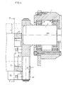
- the pivot shaft 2 is mounted in the fixed holder 1 by means of bearings 13.
- the drive provided for motorized or manual actuation of the pivot shaft 2 (in FIG. 4 on the right side of the holder 1) is not shown.
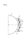
- a vertically arranged support plate 15 is firmly connected on the side of the fixed holder 1 facing the mixing container (a second such support plate 15 is of course also present on the other side of the divided mixer shaft 2; for that Understanding the invention is sufficient to describe the right half of the mixing device, which is schematically illustrated in FIG. 3).
- a lifting device which consists of two hydraulic cylinders 16, 17 arranged on different sides of the pivot shaft 2. These hydraulic cylinders are fastened to the support plate 15 by means of claws 18 and screws 19.
- the support plate 15 carries two guide rods 20, 21 which are arranged parallel to one another in a vertical plane.
- the second container part 6 is fixedly connected to an upper guide plate 22 and a lower guide plate 23. These two guide plates 22, 23 are guided on the guide rods 20, 21 and can be equipped with sliding bushes 24 for this purpose.
- the second container part 6 can therefore be lowered and then raised in order to be pivoted into the mixed position.
- the lowest position of the second container part 6 is generally expedient when the first container part 5 is removed, when the pivotable second container part 6 with the drive motor 9 carried by it is pivoted in the most balanced position for cleaning purposes, for example by 90 ° (ie in an approximately horizontal position) should.
- An intermediate position of the second container part 6 results when it is to be lowered onto a lower container part 5 to be coupled.
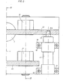
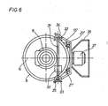
- FIG. 6 shows a further exemplary embodiment of the invention, in which the second container part 6 is raised and lowered by an electric motor 30 (slip-on geared motor).
- the electric motor 30 acts on a horizontally arranged threaded spindle 31, which is in engagement with two threaded spindles 34, 35 via a bevel gear 32 and 33, respectively.
- the second container part 6 is raised and lowered via these threaded spindles.
- guide rods 20 ', 21' are provided, which are arranged on a support plate 15 '.
- the stand of the mixing device is designated 36. It carries a motor 37 by means of which the mixing container pivots about the horizontal pivot axis 14.
- a first device (not illustrated in detail) is expediently provided, which responds when the torque generated by the first and / or second container part 5 or 6 about the pivot axis 14 exceeds a certain value and then the lifting device (ie the electric motor 30) operated in the sense of reducing this torque.
- a second device is also provided which interrupts the further pivoting movement of the first and / or second container part 5 or 6 until the torque generated by the first and / or second container part about the pivot axis 14 when the said first device responds a predetermined minimum value is reduced.
- the lifting device expediently lowers the mixing container only when an approximately vertical position is reached in order to keep the otherwise increasing torque low. In this way, the lifting device is not only used for lifting and lowering the second container part, but also for weight or. Torque compensation used.
- drive motor 9 of the agitator is attached to the pivotable mixing container in the exemplary embodiments explained, a stationary drive motor can be used within the scope of the invention.
Landscapes
- Chemical & Material Sciences (AREA)
- Chemical Kinetics & Catalysis (AREA)
- Mixers With Rotating Receptacles And Mixers With Vibration Mechanisms (AREA)
- Accessories For Mixers (AREA)
- Mixers Of The Rotary Stirring Type (AREA)
Applications Claiming Priority (2)
| Application Number | Priority Date | Filing Date | Title |
|---|---|---|---|
| DE19853512257 DE3512257A1 (de) | 1985-04-03 | 1985-04-03 | Mischvorrichtung |
| DE3512257 | 1985-04-03 |
Publications (3)
| Publication Number | Publication Date |
|---|---|
| EP0197399A2 true EP0197399A2 (fr) | 1986-10-15 |
| EP0197399A3 EP0197399A3 (en) | 1989-01-25 |
| EP0197399B1 EP0197399B1 (fr) | 1990-03-28 |
Family
ID=6267252
Family Applications (1)
| Application Number | Title | Priority Date | Filing Date |
|---|---|---|---|
| EP86103920A Expired - Lifetime EP0197399B1 (fr) | 1985-04-03 | 1986-03-21 | Dispositif pour mélanger |
Country Status (2)
| Country | Link |
|---|---|
| EP (1) | EP0197399B1 (fr) |
| DE (2) | DE3512257A1 (fr) |
Cited By (1)
| Publication number | Priority date | Publication date | Assignee | Title |
|---|---|---|---|---|
| DE3637607A1 (de) * | 1986-11-05 | 1988-05-11 | Herfeld Ute | Mischvorrichtung |
Families Citing this family (3)
| Publication number | Priority date | Publication date | Assignee | Title |
|---|---|---|---|---|
| DE4335285A1 (de) * | 1993-10-15 | 1995-04-20 | Herfeld Gmbh & Co Kg Dr | Mischvorrichtung |
| DE19809476C2 (de) * | 1998-03-06 | 2001-02-22 | Ruberg Mischtechnik Kg | Mischer |
| US6331070B1 (en) * | 2000-10-30 | 2001-12-18 | Reliance Industries, Inc. | Process and apparatus for particle size reduction and homogeneous blending of ingredients in a fluidized change can mixer |
Family Cites Families (9)
| Publication number | Priority date | Publication date | Assignee | Title |
|---|---|---|---|---|
| DE1082882B (de) * | 1955-03-25 | 1960-06-09 | Vollrath Fa Paul | Misch- oder Knetmaschine |
| GB890355A (en) * | 1960-12-16 | 1962-02-28 | Polymar Sursee Ag | Improvements in or relating to mixing and kneading machines for pastes and powders |
| US3224741A (en) * | 1964-07-01 | 1965-12-21 | Sr John L Muench | Mixer |
| NL162184C (nl) * | 1970-06-16 | 1980-04-15 | Langen & Zonen Bv | Inrichting voor rotatie-aandrijving van een transport- vat. |
| DE2110047C2 (de) * | 1971-03-03 | 1983-01-20 | Herfeld, Dipl.-Volksw. Dr., Friedrich Walter Adolf, 5982 Neuenrade | Mischvorrichtung |
| DE2504126A1 (de) * | 1974-02-06 | 1975-08-07 | Ortuno Salvador Garcia | Mahl-,misch- und ruehrvorrichtung |
| DE2946126C2 (de) * | 1979-11-15 | 1986-08-14 | Dieter 6570 Kirn Kupka | Ruhrwerk |
| DE3123362A1 (de) * | 1981-06-12 | 1982-12-30 | Herfeld, Friedrich Walter, Dr., 5982 Neuenrade | Mischvorrichtung |
| FR2567415B1 (fr) * | 1984-07-12 | 1990-04-13 | Gallay Sa | Appareil melangeur pour produits pulverulents |
-
1985
- 1985-04-03 DE DE19853512257 patent/DE3512257A1/de not_active Withdrawn
-
1986
- 1986-03-21 EP EP86103920A patent/EP0197399B1/fr not_active Expired - Lifetime
- 1986-03-21 DE DE8686103920T patent/DE3669832D1/de not_active Expired - Fee Related
Cited By (1)
| Publication number | Priority date | Publication date | Assignee | Title |
|---|---|---|---|---|
| DE3637607A1 (de) * | 1986-11-05 | 1988-05-11 | Herfeld Ute | Mischvorrichtung |
Also Published As
| Publication number | Publication date |
|---|---|
| DE3669832D1 (de) | 1990-05-03 |
| DE3512257A1 (de) | 1986-10-09 |
| EP0197399B1 (fr) | 1990-03-28 |
| EP0197399A3 (en) | 1989-01-25 |
Similar Documents
| Publication | Publication Date | Title |
|---|---|---|
| DE202023105032U1 (de) | Dampfturbinenrotor-Wartungsvorrichtung | |
| DE9108825U1 (de) | Scherenhubtisch | |
| DE3529559A1 (de) | Transmissionsbetaetigungsvorrichtung | |
| DE8112327U1 (de) | Kombinierte hobelmaschine mit wenigstens einem saegewerkzeug, wenigstens einem fraeswerkzeug und wenigstens einem stemmwerkzeug | |
| DE69408471T2 (de) | Vorrichtung zum stellen einer glasscheibe für einen laden | |
| DE1175852B (de) | Hebebuehne | |
| EP0197399B1 (fr) | Dispositif pour mélanger | |
| DE1801343A1 (de) | Laufkran fuer Giesstiegel | |
| DE2845051C2 (de) | Walzstraße mit auswechselbaren Gerüsten | |
| DE2936688A1 (de) | Zur handhabung schwerer lasten dienende drehbare vorrichtung | |
| DE29905551U1 (de) | Vorrichtung zum Transportieren und Entleeren von Abfall-Behältern | |
| DE1630865A1 (de) | Faltbare Bordwand fuer Lastkraftwagen | |
| DE3442940A1 (de) | Hebetisch | |
| DE2856350C2 (de) | Fahrzeug zum wahlweisen Transport von Stückgut oder Coils | |
| DE2803895C2 (de) | Gießereikran | |
| DE2902918C2 (de) | Kastenaufbau, insbesondere für Tiertransportfahrzeuge | |
| DE3013590C2 (de) | Knetmaschine mit einem rotierend angetriebenen Bottich | |
| DE575933C (de) | Vorschubgetriebe, das ausserdem zum Heben und Senken des Arbeitstisches von Konsolfraesmaschinen, insbesondere Starrfraesmaschinen, dient | |
| EP0669080B1 (fr) | Dispositif pour aider la vidange d'un récipient de pâte d'une machine de pétrissage et de mélange de pâte | |
| DE3238150C2 (fr) | ||
| DE3442307A1 (de) | Hub- bzw. absetzvorrichtung fuer transportable grossbehaelter, z.b. kabinen, container oder dergleichen | |
| DE1092421B (de) | Vertikalwalzwerk | |
| DE29803330U1 (de) | Hubvorrichtung | |
| AT394339B (de) | Lastfahrzeug mit einem auswechselbaren aufbau | |
| DE112023006441T5 (de) | Nebenausleger, Auslegeranordnung und Arbeitsmaschine |
Legal Events
| Date | Code | Title | Description |
|---|---|---|---|
| PUAI | Public reference made under article 153(3) epc to a published international application that has entered the european phase |
Free format text: ORIGINAL CODE: 0009012 |
|
| AK | Designated contracting states |
Kind code of ref document: A2 Designated state(s): CH DE FR GB IT LI |
|
| RAP1 | Party data changed (applicant data changed or rights of an application transferred) |
Owner name: HERFELD, UTE |
|
| RIN1 | Information on inventor provided before grant (corrected) |
Inventor name: HERFELD, FRIEDRICH WALTER, DR. |
|
| PUAL | Search report despatched |
Free format text: ORIGINAL CODE: 0009013 |
|
| AK | Designated contracting states |
Kind code of ref document: A3 Designated state(s): CH DE FR GB IT LI |
|
| 17P | Request for examination filed |
Effective date: 19890612 |
|
| 17Q | First examination report despatched |
Effective date: 19890901 |
|
| GRAA | (expected) grant |
Free format text: ORIGINAL CODE: 0009210 |
|
| ITF | It: translation for a ep patent filed | ||
| AK | Designated contracting states |
Kind code of ref document: B1 Designated state(s): CH DE FR GB IT LI |
|
| REF | Corresponds to: |
Ref document number: 3669832 Country of ref document: DE Date of ref document: 19900503 |
|
| ET | Fr: translation filed | ||
| GBT | Gb: translation of ep patent filed (gb section 77(6)(a)/1977) | ||
| PLBE | No opposition filed within time limit |
Free format text: ORIGINAL CODE: 0009261 |
|
| STAA | Information on the status of an ep patent application or granted ep patent |
Free format text: STATUS: NO OPPOSITION FILED WITHIN TIME LIMIT |
|
| 26N | No opposition filed | ||
| ITPR | It: changes in ownership of a european patent |
Owner name: CESSIONE;DR. HERFELD GMBH & CO. KG |
|
| REG | Reference to a national code |
Ref country code: FR Ref legal event code: TP |
|
| REG | Reference to a national code |
Ref country code: CH Ref legal event code: PUE Owner name: DR. HERFELD GMBH & CO. KG |
|
| REG | Reference to a national code |
Ref country code: GB Ref legal event code: 732 |
|
| ITTA | It: last paid annual fee | ||
| PGFP | Annual fee paid to national office [announced via postgrant information from national office to epo] |
Ref country code: FR Payment date: 20000214 Year of fee payment: 15 |
|
| PGFP | Annual fee paid to national office [announced via postgrant information from national office to epo] |
Ref country code: CH Payment date: 20000218 Year of fee payment: 15 |
|
| PGFP | Annual fee paid to national office [announced via postgrant information from national office to epo] |
Ref country code: GB Payment date: 20000222 Year of fee payment: 15 |
|
| PGFP | Annual fee paid to national office [announced via postgrant information from national office to epo] |
Ref country code: DE Payment date: 20000529 Year of fee payment: 15 |
|
| PG25 | Lapsed in a contracting state [announced via postgrant information from national office to epo] |
Ref country code: GB Free format text: LAPSE BECAUSE OF NON-PAYMENT OF DUE FEES Effective date: 20010321 |
|
| PG25 | Lapsed in a contracting state [announced via postgrant information from national office to epo] |
Ref country code: LI Free format text: LAPSE BECAUSE OF NON-PAYMENT OF DUE FEES Effective date: 20010331 Ref country code: CH Free format text: LAPSE BECAUSE OF NON-PAYMENT OF DUE FEES Effective date: 20010331 |
|
| GBPC | Gb: european patent ceased through non-payment of renewal fee |
Effective date: 20010321 |
|
| REG | Reference to a national code |
Ref country code: CH Ref legal event code: PL |
|
| PG25 | Lapsed in a contracting state [announced via postgrant information from national office to epo] |
Ref country code: FR Free format text: LAPSE BECAUSE OF NON-PAYMENT OF DUE FEES Effective date: 20011130 |
|
| REG | Reference to a national code |
Ref country code: FR Ref legal event code: ST |
|
| PG25 | Lapsed in a contracting state [announced via postgrant information from national office to epo] |
Ref country code: DE Free format text: LAPSE BECAUSE OF NON-PAYMENT OF DUE FEES Effective date: 20020101 |
|
| PG25 | Lapsed in a contracting state [announced via postgrant information from national office to epo] |
Ref country code: IT Free format text: LAPSE BECAUSE OF NON-PAYMENT OF DUE FEES;WARNING: LAPSES OF ITALIAN PATENTS WITH EFFECTIVE DATE BEFORE 2007 MAY HAVE OCCURRED AT ANY TIME BEFORE 2007. THE CORRECT EFFECTIVE DATE MAY BE DIFFERENT FROM THE ONE RECORDED. Effective date: 20050321 |