EP0197436A2 - Dispositif d'un commutateur - Google Patents
Dispositif d'un commutateur Download PDFInfo
- Publication number
- EP0197436A2 EP0197436A2 EP86104172A EP86104172A EP0197436A2 EP 0197436 A2 EP0197436 A2 EP 0197436A2 EP 86104172 A EP86104172 A EP 86104172A EP 86104172 A EP86104172 A EP 86104172A EP 0197436 A2 EP0197436 A2 EP 0197436A2
- Authority
- EP
- European Patent Office
- Prior art keywords
- switch
- switching
- circuit
- motor
- arrangement according
- Prior art date
- Legal status (The legal status is an assumption and is not a legal conclusion. Google has not performed a legal analysis and makes no representation as to the accuracy of the status listed.)
- Granted
Links
Images



Classifications
-
- H—ELECTRICITY
- H02—GENERATION; CONVERSION OR DISTRIBUTION OF ELECTRIC POWER
- H02P—CONTROL OR REGULATION OF ELECTRIC MOTORS, ELECTRIC GENERATORS OR DYNAMO-ELECTRIC CONVERTERS; CONTROLLING TRANSFORMERS, REACTORS OR CHOKE COILS
- H02P3/00—Arrangements for stopping or slowing electric motors, generators, or dynamo-electric converters
- H02P3/06—Arrangements for stopping or slowing electric motors, generators, or dynamo-electric converters for stopping or slowing an individual dynamo-electric motor or dynamo-electric converter
-
- H—ELECTRICITY
- H01—ELECTRIC ELEMENTS
- H01H—ELECTRIC SWITCHES; RELAYS; SELECTORS; EMERGENCY PROTECTIVE DEVICES
- H01H21/00—Switches operated by an operating part in the form of a pivotable member acted upon directly by a solid body, e.g. by a hand
- H01H21/02—Details
-
- H—ELECTRICITY
- H01—ELECTRIC ELEMENTS
- H01H—ELECTRIC SWITCHES; RELAYS; SELECTORS; EMERGENCY PROTECTIVE DEVICES
- H01H21/00—Switches operated by an operating part in the form of a pivotable member acted upon directly by a solid body, e.g. by a hand
- H01H21/02—Details
- H01H21/18—Movable parts; Contacts mounted thereon
- H01H21/36—Driving mechanisms
- H01H21/52—Driving mechanisms with means for introducing a predetermined time delay
-
- H—ELECTRICITY
- H01—ELECTRIC ELEMENTS
- H01H—ELECTRIC SWITCHES; RELAYS; SELECTORS; EMERGENCY PROTECTIVE DEVICES
- H01H2300/00—Orthogonal indexing scheme relating to electric switches, relays, selectors or emergency protective devices covered by H01H
- H01H2300/002—Application electric motor braking, e.g. pole reversal of rotor, shorting motor coils, also for field discharge
Definitions
- the invention relates to a switch arrangement according to the type of the main claim.
- phase gating controls which have an alternating current switch, usually a triac in series with the electric motor, the speed or behavior of which should be controlled, regulated or influenced.
- Such triac controls are known in many forms and are often already available in prefabricated components for the desired application, these components containing integrated circuits, that is to say ICs, which then take on the respective intended task with an additional external circuit.
- switch-on and switch-off means in series with the electric motor driving the respective tools or systems of the device, as well as a load resistor, as a result of which the current flowing through the triac and necessarily also through the electric motor is detected and for control purposes, for example for constant speed control , which can also be adjusted continuously or in stages, can be used.
- control of such switch arrangements or speed controls from the outside can be designed so that only one actuator from. the user is to be moved, with a switch first being switched and then, for example, by sliding the actuating element, a slider can be moved on a potentiometer in such a way that the IC for the speed control provides different resistance values in the control circuit of the triac, which means that the is then able to specify different speeds and then comply with a corresponding full shaft control, including with load compensation.
- the problem with such controls and circuits can be the fact that the integrated component, that is to say the IC, heats itself up and then, despite constant external wiring, the controlled variable runs away to a greater or lesser extent.
- the integrated circuit U 210 B from Telefunken, which can be used as a speed controller with load current compensation, whereby this component is used by appropriate selection and combination of additional external circuit component values can be adapted to the respective motors and the required functional conditions.
- the speed control takes place via a speed controller provided as a potentiometer, although no external power switch is provided in the application sheets issued by the manufacturer for the U 210 B circuit, but could be arranged as desired.
- Two-pole switching switches or on-off switches are generally known (DE-OS 32 20 189), for example in the form of a potentiometer-switch combination, with a linear potentiometer arranged directly on a support plate, snap switches with their respective switching levers being arranged on both sides of its tapping tracks, that when a slide bearing the slider of the potentiometer is moved from this mirror-symmetrical rear surfaces of the shift levers can be actuated when the slide has reached a predetermined changeover position, as a result of which double-pole electrical contacts are made.
- the invention is therefore based on the object to improve the aforementioned switch arrangement so that the smallest possible wear on the switches and in particular in coal / collector region of the electric motor in the A-swith or Drehiereste 'results in L augmentation, at the same time a switch training with two-pole changeover, which can be used in this context:
- the switch arrangement according to the invention solves this problem with the characterizing features of the main claim and has the advantage that a preset constant speed can be maintained particularly sensitively, with influences attributable to load compensation by appropriate dimensioning of the IC module directly connected, therefore with this circuit element directly related to heat transfer and its temperature response can be compensated.
- the invention therefore ensures that where a short-circuit rapid braking is required, the same procedure is followed, but on the other hand the wear-free shutdown and the stopping of the electric motor is permitted if this is possible without problems.
- an intimate thermal relationship to the speed control IC is achieved by sticking an NTC resistor or preferably a diode directly onto the housing of the IC and connecting it to the corresponding external circuitry or connects to inputs of the IC, furthermore in the area of the power switch at the same time means are provided which are designed as changeover switches so that the short-circuit rapid braking can be implemented in the other switching position. This is possible at any time, even if the - speed controller has not previously moved to the off position.
- the safety brake switch used allows a simple actuation of the shift lever (in vertical and horizontal direction to the circuit board on which it is attached) with a simple structure and enables a safe two-pole changeover, with the particular advantage that the special type of construction of the invention
- the switch can also be made deliberately in time for the respective switchover, so that the switch according to the invention is preferred as such a safety switch in electrical machines and the like. can be used in which a safety device must be taken into account in order to then be able to switch on the device with a separate main switch.
- the braking of electric motors made possible by the invention by means of only a two-pole changeover switch with a defined timing sequence is therefore particularly advantageous, as a result of which the braking of universal motors, which is fundamentally known per se, namely essentially braking by reversing the polarity of the motor armature with a short circuit via the field windings, in significantly simplified and, above all, also leads to a significantly lower load on the contacts of the switch, the carbon and the lamellae of the motor armature.
- the speed controller with load compensation shown in FIGS. 1 and 2 as a central circuit element in the form of a module with an integrated circuit (IC) is available under the designation U 210 B, for example from telephones and controls the triac Tc with its output 4 * . which is in the circuit of the electric motor M, which is indicated symbolically in the drawing by an upper field winding F1, the armature A and a lower field winding F2.
- the input circuit for the mains supply U N is completed by a double-pole changeover switch S, consisting of the two individual changeover switches S1 and S2, which together at 9 have an actuator, a cam, a shift lever, an actuating element or the like.
- the actuating element in the application-oriented case of a food processor can be, for example, a cam actuated when the cover of the food processor is removed or a push rod. If the lid of the food processor is put on, then the actuating element moves in the direction of arrow B, so that the two changeover switches S1 and S2 switch to the other position, not shown in the illustration in FIG.
- the switch position of S1, S2 shown in FIG. 1 shows the short-circuit fast circuit, in which only the one field winding F1 is short-circuited in series with the armature winding A via the lines L1 and L2 with one-sided disconnection from the network.
- This quick stop circuit for the motor in which the motor is braked immediately by reversing the polarity of the motor armature and short-circuiting the fields via switches S1 and S2, presupposes - and here switch S1 is also used as the main power switch - that as realized according to a feature of the present invention, the switch S2 switches first when the device is switched on, that is to say in advance of the switch S1 toggling.
- switch S1 When switching off or switching over to braking (in the switch position shown), switch S1 must first switch over in the dynamic switching sequence, that is to say in advance, and then switch S2.
- switch S1 does not switch over to switch S2 in advance, i.e. if one assumes that switch S1 differs from that shown in FIG. 1 Position would still be in the on position; in this case the armature A of the motor would be bridged and the current through the two field windings F1, F2 would destroy the triac Tc. The same would happen when switching on, if switch S1 makes the mains connection ahead of switch S2 (which must not happen).
- the circuit of FIG. 1 has a step switch Ss as a speed controller instead of a potentiometer, which can be switched from an off position to switching positions x, y, z which specify higher speeds; the momentary position shown in FIG. 1 can then be temporarily adjusted, for example, by a separate keying by switch axial movement, not by a switch rotation.
- the step switch Ss is therefore adjustable from the off position to the three different speed positions and connects the connections 8 * , 12 * and 13 * of the integrated circuit IC to the other voltage connection (lower busbar US).
- the usual operation of a device provided with such a control circuit in accordance with FIGS. 1 and 2 is therefore such that after the finished construction of the device, for example a lid of a food processor, the positions of the switches S1, S2 are switched and the device is connected to the mains; the switch-on then takes place separately by actuating the step switch Ss as a speed controller, by turning the switch from the off position to one of the desired speed positions x, y, z. If work with such a device is to be set, then the user is automa ti as a previous operation sch reduce the speed via the switch positions of the step switch Ss until the off position is reached again; the power supply to the motor M is thus interrupted via the triac Tc.
- the device can then be opened at any time, as a result of which the (one-sided) mains disconnection and the short-circuit rapid braking of the motor are then implemented simultaneously via the actuating element and corresponding actuation of the two switches S1, S2.
- This rapid braking can therefore, since the opening of the device is completely arbitrary, if necessary at all, either take place with the engine already stopped, which means that no short-circuit rapid braking is initiated, or at any earlier point in time, with short-circuit currents which are then always greatly reduced, and in this respect essentially also wear-reducing or wear-free.
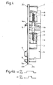
- a prerequisite for the formation of the mains short-circuit brake double changeover switch S is the ability of the two partial changeover switches S1 and S2 to be actuated jointly via the actuating element that they switch dynamically in accordance with the diagram in FIG. 4a, as explained further on.
- Switches with such switchover options can be designed mechanically so that when the actuating element for the switchover is a unitary common component, the one switch, here S1 the other, in terms of its switching movements when switched on after and when switched off, runs in time Y.
- the carrier and bearing material for the illustrated double-pole changeover switch S that is, in other words, its housing, a carrier plate 20, a printed circuit board, printed circuit board or the like, which is usually a component side 20a and the conductor track side 20b includes (see Fig. 4).
- the circuit elements and components of the double-pole changeover switch or on / off switch S are shown on the component or component side; This consists of the first changeover switch S1 and the second changeover switch S2, which are arranged opposite one another so that the two biasing and at the same time dead center springs 15, 16 for actuating the switching arm on both sides on the same, common, external switching movement accessible actuating element or, as this in the following is only referred to, shift lever 9 are arranged.
- a suitable material preferably metallic, respectively angled support or holding parts 1, 2, 3, 4 for the contact pieces 1a, 2a, 3a and 4a, against which the mating contact pieces 19 attach themselves to the respective between the two contact pieces 1a, 2a ; 3a, 4a or holding parts 1, 2, 3, 4 move the movable switching arm 17, 18 to the system secured by an over dead center position.
- the respective switching arm 17, 18 sits, forked at its lower end, because the respective over-center spring 15, 16 passes between the two fork tines, on its own contact-holding part 5, 6 in a kind of cutting position, is therefore easy and freely movable and therefore tilts when the shift lever moves substantially along the direction of the double arrow A, each pulled by the associated bias spring 15, 16, into the corresponding shift positions.
- the two bias springs 15, 16 are each attached to the pivot point of the switching arms 17, 18 at a distance from them and with their other ends in the two-sided receiving openings 21 a, 2 b on the switching lever 9, more precisely on a substantially right-angled continuation 9 a of the same.
- the shift lever 9 has a pivot point at 22 with the circuit board 20, namely it has a pivot pin 10 (Fig. 4) which is inserted through a corresponding pivot opening in the circuit board, so that the shift lever 9 can pivot about the pivot point 22 ; it is itself formed starting from the pivot point 22 in an approximately arcuate manner in the plane of FIG. 3 and extends with its preferably one-piece continuation 9a between the two changeover switches S1, S2, so that the bias springs 15, 16, as mentioned, on this Projection can be attached.
- the switching lever 9 itself has its own bias spring 12, which is supported at 13 on the holding part 5 of the one changeover switch S2, which at the same time also sags the switching arm 17, and on the opposite side a securing pin 11 on the switching lever 9 includes up to a predetermined height.
- the shift lever movement can then basically take place by any acting means, for example by a linear pressure effect according to the arrow B or by the rotary movement of an eccentric part C, which acts on the rear surface of the shift lever at 24 and causes it to pivot to the left in the plane of the drawing prompted.
- the switching lever 9 is secured in that two resilient latching members 13 and 14 are arranged on it, preferably with molded noses 13a, 14a, which engage behind the circuit board on the other side; these locking elements are provided with their locking lugs by provided elongated arcuate openings 25, 26 are pushed through in the printed circuit board, whereupon they then expand again due to their at least partially resilient properties on the conductor side 20b and the locking lugs 13a, 14a lock and support the switching lever against lifting off.
- the spring tension of the two biasing tension springs 15, 16 is such that the required contact force at the contact points is ensured in the respective top dead center positions of the switching arm.
- the switch function in the illustrated embodiment is also provided with a special feature which consists in the fact that the shift lever 9, more precisely its projection 9a, describes a circular arc around the pivot point 22, and since the two suspension points of the springs 15 and 16 are at different distances from the pivot point 22 , cover different distances even with the same angle of rotation of the shift lever;
- This special feature is used by the present invention for the advantageous embodiment of setting the time switch on / off points of the two changeover switches S1, S2 differently, and preferably as shown in a very schematic form in the diagram of FIG. 4a.
- the basic function is therefore such that due to the different circular arc configuration of the switching movements for the two bias springs when the switching lever is actuated counterclockwise (in the drawing plane from right to left), the switching lever 17 snaps into the other switching position defined, for example, as the Eln position, and only then with a time delay, as shown in FIG. 4a, does the switching tongue 18 carry out the switching movement because of the larger circular arc to be covered.
- the two-pole changeover switch S operates when opening, that is to say when the shift lever 9 moves from left to right.
- the shift lever 18 is the first to move to the other position, ie "opens" according to a predetermined definition, and then the shift arm 17 also opens.
- Such a switching behavior can therefore preferably be applied to a device for braking any electric universal motor in which, for reasons of handling safety for the user, there is a desire or necessity for the device to come to a standstill after the shortest possible time after being switched off.
- This can be the case with power tools, electric hand tools, kitchen machines etc., circular saws, lawn mowers, hedge trimmers etc.
- a similar quick switch-off function or braking is also provided for a large number of machines when certain parts are removed, the device is opened, a cover is lifted or the like the like; in this case, too, braking is initiated immediately, for which purpose certain circuits or means for motor braking can be used, which can be mechanical or electrical.
- Electric motor brakes are, for example, brake motors, eddy current brakes, DC brakes, or braking by reversing the polarity of the motor armature with a short circuit across the fields and the like.
- FIG. 5a requires a four-way switch in order to completely disconnect the motor from the mains on the one hand and on the other hand, as shown to short-circuit windings W1 and W2 in the switched-off position via the armature of the motor;
- a triple changeover switch is required in the known representation of FIG. 5b, while in the representation of FIG.
- 5c complete disconnection from the mains is required provided that a two-way switch or two-pole switch and a simple on / off switch are still required, although the armature winding must not be electrically between the two fields; 5c in this electrical circuit allows the use of only two change-over switches or a double-pole change-over switch in the absence of complete network separation.
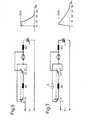
- the invention now enables a substantial reduction in these short-circuit currents with only an insignificant increase in the braking times, as the diagrams show; in accordance with the circuits of FIGS. 6 and 7.
- a prerequisite for the safe functioning of the circuits shown in FIGS. 5c, 6 and 7 is, however, that when the motor is switched on - (all switch positions of FIGS. 5a, 5b, 5c, 6 and 7 are shown in the braking position) the switch S2 leads the switch S1, while when switching off or when switching to braking, the switch S1 leads the switch S2 in the same way as indicated in Fig. 4a, otherwise, as can be verified, both motor fields without anchors directly on the network could lie, which can result in high current pulses again, which can damage the contact and the motor and possibly destroy a triac used for phase control, which is in series with the motor.
- a preferred area of application of the two-pole toggle switch or off switch according to the invention is therefore the use in motor brake circuits or safety circuits in general, since the switch according to the invention can in any case disconnect from the mains with one pole.
- a resulting change in speed is switched off in accordance with a further feature of the present invention in that an immediate temperature compensation is carried out, in such a way that a switching element with a temperature response is brought into direct heat-conducting connection with the housing G including the integrated circuit IC, for example by attaching the switching element directly on the IC, preferably in the middle of the housing by means of adhesive, casting compound or the like. and utilization of the temperature response resulting at electrical connections of this circuit element by connecting to external circuit elements and / or directly to input connections of the integrated circuit IC. Since the IC temperature is transmitted directly to the compensation circuit element in this way, only such a selection or determination of the temperature response of this circuit element S T is necessary that the speed-changing temperature change of the IC is compensated.
- a first exemplary embodiment corresponding to FIG. 1 uses an NTC resistor as the circuit element S T , the connections of which are connected in parallel with a resistor R6 'which connects the circuit point P1 to the soft, possibly via resistors R, R', the speed controller step contacts, connects to the other terminal of the capacitor C3 or the IC terminal pin 13 already mentioned.
- a temperature compensation result if, instead of the NTC resistor, as shown in FIG. 2, all other circuit elements in FIG. 2 correspond to the Representation of Fig. 1 and therefore need not be mentioned further, uses a diode D, the permeability changes linearly to the temperature, whereby it is possible with the circuit shown to completely eliminate a change in speed at the beginning of the temperature rise and in the case of extreme excess temperature .
- the diode D which is also arranged in an intimately thermally conductive relationship with the housing of the IC, is in the embodiment of FIG. 2 in series with a resistor R7 and at the other terminal of the capacitor C3 (pin 12 of the IC).
- the integrated circuit IC used represents a certain mass and therefore also a corresponding temperature inertia, it is possible to also use a further temperature sensor (not shown in the drawing), a diode or an NTC resistor to also record the ambient temperature and include it in the compensation to include.
Landscapes
- Engineering & Computer Science (AREA)
- Power Engineering (AREA)
- Stopping Of Electric Motors (AREA)
- Operating, Guiding And Securing Of Roll- Type Closing Members (AREA)
- Control Of Ac Motors In General (AREA)
- Push-Button Switches (AREA)
Priority Applications (1)
| Application Number | Priority Date | Filing Date | Title |
|---|---|---|---|
| AT86104172T ATE78951T1 (de) | 1985-04-01 | 1986-03-26 | Schalteranordnung. |
Applications Claiming Priority (4)
| Application Number | Priority Date | Filing Date | Title |
|---|---|---|---|
| DE3511895 | 1985-04-01 | ||
| DE19853511895 DE3511895A1 (de) | 1985-04-01 | 1985-04-01 | Schalteranordnung |
| DE3511893 | 1985-04-01 | ||
| DE19853511893 DE3511893A1 (de) | 1985-04-01 | 1985-04-01 | Zweipoliger umschalter und seine verwendung als sicherheitsschalter bei elektrischen maschinen |
Publications (3)
| Publication Number | Publication Date |
|---|---|
| EP0197436A2 true EP0197436A2 (fr) | 1986-10-15 |
| EP0197436A3 EP0197436A3 (en) | 1988-07-06 |
| EP0197436B1 EP0197436B1 (fr) | 1992-07-29 |
Family
ID=25830967
Family Applications (1)
| Application Number | Title | Priority Date | Filing Date |
|---|---|---|---|
| EP86104172A Expired - Lifetime EP0197436B1 (fr) | 1985-04-01 | 1986-03-26 | Dispositif d'un commutateur |
Country Status (4)
| Country | Link |
|---|---|
| US (1) | US4725764A (fr) |
| EP (1) | EP0197436B1 (fr) |
| AT (1) | ATE78951T1 (fr) |
| DE (1) | DE3686189D1 (fr) |
Cited By (2)
| Publication number | Priority date | Publication date | Assignee | Title |
|---|---|---|---|---|
| EP0718859A1 (fr) * | 1994-12-19 | 1996-06-26 | Heinrich Kopp Ag | Dispositif pour la commutation d'un moteur électrique, en particulier pour le freinage d'un outil électrique |
| EP0858151A1 (fr) * | 1997-02-06 | 1998-08-12 | Black & Decker Inc. | Appareil et dispositif de freinage pour moteurs électriques |
Families Citing this family (13)
| Publication number | Priority date | Publication date | Assignee | Title |
|---|---|---|---|---|
| US6765310B1 (en) | 2001-05-07 | 2004-07-20 | Multicraft International | Programmed virtual multi-pole or multi-throw switch for outdoor power equipment and method |
| DE10234397A1 (de) * | 2002-07-23 | 2004-01-29 | C. & E. Fein Gmbh & Co Kg | Gebremster Reihenschlussmotor und Verfahren zum Bremsen eines Reihenschlussmotors |
| FR2867322B1 (fr) * | 2004-03-03 | 2006-04-21 | Seb Sa | Appareil electromenager incluant un moteur electrique |
| US9120543B2 (en) | 2014-01-03 | 2015-09-01 | Eric Toce | Boat hoist apparatus and method of use |
| EP2947765B1 (fr) | 2014-05-20 | 2020-08-26 | Black & Decker Inc. | Freinage électronique destiné à un moteur universel dans un outil électrique |
| US11047528B2 (en) | 2016-02-12 | 2021-06-29 | Black & Decker Inc. | Electronic braking for a power tool having a brushless motor |
| US10433842B2 (en) | 2017-04-07 | 2019-10-08 | Lexington Medical, Inc. | Surgical handle assembly |
| WO2019177753A1 (fr) | 2018-03-16 | 2019-09-19 | Milwaukee Electric Tool Corporation | Serre-lame pour outil électrique |
| EP3774148B1 (fr) | 2018-04-03 | 2025-02-12 | Milwaukee Electric Tool Corporation | Scie sauteuse |
| USD887806S1 (en) | 2018-04-03 | 2020-06-23 | Milwaukee Electric Tool Corporation | Jigsaw |
| US10856871B2 (en) | 2019-01-16 | 2020-12-08 | Lexington Medical, Inc. | Advancing a toothed rack of a surgical handle assembly |
| US11622764B2 (en) | 2021-04-27 | 2023-04-11 | Lexington Medical, Inc. | Surgical handle assembly |
| US12343009B2 (en) | 2021-06-07 | 2025-07-01 | Lexington Medical, Inc. | Motorized surgical handle assembly |
Family Cites Families (23)
| Publication number | Priority date | Publication date | Assignee | Title |
|---|---|---|---|---|
| US2912632A (en) * | 1957-08-23 | 1959-11-10 | Ite Circuit Breaker Ltd | Motor reversing and dynamic braking circuit |
| US3043928A (en) * | 1961-03-01 | 1962-07-10 | Illinois Tool Works | Snap switch |
| US3280401A (en) * | 1963-11-15 | 1966-10-18 | Clark Equipment Co | Hydraulic speed control system with braking |
| US3548276A (en) * | 1969-02-17 | 1970-12-15 | Thomas A O Gross | Dynamic braking of universal motors |
| US3689812A (en) * | 1970-02-14 | 1972-09-05 | Siemens Ag | Generator-fed motor control with dynamic braking for vehicle propulsion |
| US3628112A (en) * | 1970-06-01 | 1971-12-14 | Thomas A O Gross | Dynamic braking of electric motors with load changing during braking |
| US3794898A (en) * | 1973-02-26 | 1974-02-26 | T Gross | Dynamic braking of electric motors with thermistor braking circuit |
| US3965404A (en) * | 1973-08-17 | 1976-06-22 | Cordem Corporation | Apparatus and method of braking a universal motor for operating a compact winch |
| GB1558591A (en) * | 1975-11-18 | 1980-01-09 | Sevcon Ltd | Pulse controllers for de motors |
| JPS5262616A (en) * | 1975-11-19 | 1977-05-24 | Hitachi Ltd | Electric car braking controller |
| DE2624236A1 (de) * | 1976-05-29 | 1977-12-15 | Licentia Gmbh | Schaltanordnung zum bremsen eines universalmotors |
| DE2655574A1 (de) * | 1976-12-08 | 1978-06-15 | Bosch Siemens Hausgeraete | Drehzahlveraenderbarer elektromotorischer antrieb, insbesondere fuer hausgeraete, wie teigruehrer o.dgl. |
| DE2802133C2 (de) * | 1978-01-19 | 1985-05-02 | Bsg Schalttechnik Gmbh & Co Kg, 7460 Balingen | Schnappschalter |
| JPS582522B2 (ja) * | 1978-03-31 | 1983-01-17 | 株式会社デンソー | 電気車制御装置 |
| DE2842145A1 (de) * | 1978-09-28 | 1980-04-17 | Metabowerke Kg | Universalmotor mit bremsschaltung |
| EP0033353A1 (fr) * | 1980-02-05 | 1981-08-12 | Black & Decker Inc. | Procédé et appareil pour contrôler la vitesse de rotation d'une perceuse, d'un fleuret à percussion ou d'un marteau rotatif |
| JPS56148102A (en) * | 1980-04-16 | 1981-11-17 | Hitachi Ltd | Control equipment of electric rolling stock |
| DE3048999A1 (de) * | 1980-12-24 | 1982-07-15 | Robert Bosch Gmbh, 7000 Stuttgart | Schaltungsanordnung zur energierueckgewinnung bei choppergesteuerten reihenschlussmaschinen |
| DE3201036A1 (de) * | 1982-01-15 | 1983-07-28 | Black & Decker, Inc., 19711 Newark, Del. | "schaltungsanordnung fuer den links- und rechtslauf von kollektormotoren" |
| DE3220189C2 (de) * | 1982-05-28 | 1986-04-24 | Bsg Schalttechnik Gmbh & Co Kg, 7460 Balingen | Schiebepotentiometer-Schalter-Kombination |
| JPS603817A (ja) * | 1983-06-20 | 1985-01-10 | 株式会社東海理化電機製作所 | モ−タ制御用スイツチ装置 |
| JPS6012625A (ja) * | 1983-07-04 | 1985-01-23 | 株式会社東海理化電機製作所 | モ−タ制御用スイツチ装置 |
| JPS6020870A (ja) * | 1983-07-12 | 1985-02-02 | 日立工機株式会社 | クラツチ式電動締付工具の制御方式 |
-
1986
- 1986-03-26 EP EP86104172A patent/EP0197436B1/fr not_active Expired - Lifetime
- 1986-03-26 DE DE8686104172T patent/DE3686189D1/de not_active Expired - Fee Related
- 1986-03-26 AT AT86104172T patent/ATE78951T1/de not_active IP Right Cessation
- 1986-03-27 US US06/844,863 patent/US4725764A/en not_active Expired - Fee Related
Cited By (2)
| Publication number | Priority date | Publication date | Assignee | Title |
|---|---|---|---|---|
| EP0718859A1 (fr) * | 1994-12-19 | 1996-06-26 | Heinrich Kopp Ag | Dispositif pour la commutation d'un moteur électrique, en particulier pour le freinage d'un outil électrique |
| EP0858151A1 (fr) * | 1997-02-06 | 1998-08-12 | Black & Decker Inc. | Appareil et dispositif de freinage pour moteurs électriques |
Also Published As
| Publication number | Publication date |
|---|---|
| EP0197436B1 (fr) | 1992-07-29 |
| ATE78951T1 (de) | 1992-08-15 |
| EP0197436A3 (en) | 1988-07-06 |
| US4725764A (en) | 1988-02-16 |
| DE3686189D1 (de) | 1992-09-03 |
Similar Documents
| Publication | Publication Date | Title |
|---|---|---|
| EP0197436A2 (fr) | Dispositif d'un commutateur | |
| DE2417954A1 (de) | Relais | |
| DE3546719C2 (en) | Switching circuit for rpm control of electrical machine | |
| EP0326146A1 (fr) | Circuit de freinage pour un moteur universel | |
| DE2751740A1 (de) | Elektroantrieb mit drehwinkelbegrenzung | |
| DE1438897A1 (de) | Schaltungsanordnung zum Betrieb einer Gesenkpresse mit durchbiegungsfaehigem Gesenkarm | |
| DE2746845A1 (de) | Einrichtung zur einschaltstrombegrenzung fuer wechselspannungsbetriebene verbraucher | |
| DE3511895A1 (de) | Schalteranordnung | |
| DE2704382A1 (de) | Elektrischer steuerschalter | |
| DE102011118488A1 (de) | Motorantrieb für Stufenschalter | |
| DE3511894A1 (de) | Drehzahlsteuerung fuer elektrische maschinen | |
| DE2414884C3 (de) | Thermischer Umschalter | |
| DE3817528A1 (de) | Motorstarter mit kurzschlussschutz | |
| DE959837C (de) | Anwendung eines Bimetallschalters als Zeitrelais | |
| DE2254937A1 (de) | Antrieb | |
| DE3334671A1 (de) | Mehrzweckschalter fuer videokameras | |
| DE1816565A1 (de) | Motorsteuerung durch einen gesteuerten Silizium-Gleichrichter mit Schalter zur Auswahl zweier Geschwindigkeitsbereiche | |
| DE3433550C2 (fr) | ||
| DE3032874C2 (de) | Einrichtung zur Steuerung des selbsttätigen Parallellaufs einer Vielzahl von Transformatoren | |
| EP1797635A1 (fr) | Dispositif pour commander par niveaux un moteur a courant continu destine a un ventilateur de refroidissement d'un vehicule automobile | |
| DE2421428C3 (de) | Grillgerät mit einer elektrischen Antriebseinrichtung für den Grillguthalter | |
| DE918275C (de) | Elektrische Gangschaltung fuer Mehrganggetriebe von Werkzeugmaschinen | |
| DE2910492A1 (de) | Stromversorgungsschaltung mit zwei leistungsstufen | |
| DE3526803A1 (de) | Schaltgeraetekombination | |
| DE669088C (de) | Scheinwerfer mit elektromotorisch angetriebener Blende und/oder Streuersaetzen |
Legal Events
| Date | Code | Title | Description |
|---|---|---|---|
| PUAI | Public reference made under article 153(3) epc to a published international application that has entered the european phase |
Free format text: ORIGINAL CODE: 0009012 |
|
| AK | Designated contracting states |
Kind code of ref document: A2 Designated state(s): AT BE CH DE FR GB IT LI LU NL SE |
|
| PUAL | Search report despatched |
Free format text: ORIGINAL CODE: 0009013 |
|
| AK | Designated contracting states |
Kind code of ref document: A3 Designated state(s): AT BE CH DE FR GB IT LI LU NL SE |
|
| 17P | Request for examination filed |
Effective date: 19880803 |
|
| 17Q | First examination report despatched |
Effective date: 19900802 |
|
| GRAA | (expected) grant |
Free format text: ORIGINAL CODE: 0009210 |
|
| AK | Designated contracting states |
Kind code of ref document: B1 Designated state(s): AT BE CH DE FR GB IT LI LU NL SE |
|
| REF | Corresponds to: |
Ref document number: 78951 Country of ref document: AT Date of ref document: 19920815 Kind code of ref document: T |
|
| REF | Corresponds to: |
Ref document number: 3686189 Country of ref document: DE Date of ref document: 19920903 |
|
| ITF | It: translation for a ep patent filed | ||
| GBT | Gb: translation of ep patent filed (gb section 77(6)(a)/1977) | ||
| ET | Fr: translation filed | ||
| PLBE | No opposition filed within time limit |
Free format text: ORIGINAL CODE: 0009261 |
|
| STAA | Information on the status of an ep patent application or granted ep patent |
Free format text: STATUS: NO OPPOSITION FILED WITHIN TIME LIMIT |
|
| 26N | No opposition filed | ||
| PGFP | Annual fee paid to national office [announced via postgrant information from national office to epo] |
Ref country code: GB Payment date: 19940311 Year of fee payment: 9 |
|
| PGFP | Annual fee paid to national office [announced via postgrant information from national office to epo] |
Ref country code: FR Payment date: 19940318 Year of fee payment: 9 |
|
| PGFP | Annual fee paid to national office [announced via postgrant information from national office to epo] |
Ref country code: SE Payment date: 19940329 Year of fee payment: 9 Ref country code: AT Payment date: 19940329 Year of fee payment: 9 |
|
| PGFP | Annual fee paid to national office [announced via postgrant information from national office to epo] |
Ref country code: NL Payment date: 19940331 Year of fee payment: 9 Ref country code: LU Payment date: 19940331 Year of fee payment: 9 |
|
| PGFP | Annual fee paid to national office [announced via postgrant information from national office to epo] |
Ref country code: BE Payment date: 19940413 Year of fee payment: 9 |
|
| PGFP | Annual fee paid to national office [announced via postgrant information from national office to epo] |
Ref country code: CH Payment date: 19940420 Year of fee payment: 9 |
|
| PGFP | Annual fee paid to national office [announced via postgrant information from national office to epo] |
Ref country code: DE Payment date: 19940504 Year of fee payment: 9 |
|
| EPTA | Lu: last paid annual fee | ||
| EAL | Se: european patent in force in sweden |
Ref document number: 86104172.1 |
|
| PG25 | Lapsed in a contracting state [announced via postgrant information from national office to epo] |
Ref country code: LU Free format text: LAPSE BECAUSE OF NON-PAYMENT OF DUE FEES Effective date: 19950326 Ref country code: GB Effective date: 19950326 Ref country code: AT Effective date: 19950326 |
|
| PG25 | Lapsed in a contracting state [announced via postgrant information from national office to epo] |
Ref country code: SE Effective date: 19950327 |
|
| PG25 | Lapsed in a contracting state [announced via postgrant information from national office to epo] |
Ref country code: LI Effective date: 19950331 Ref country code: CH Effective date: 19950331 Ref country code: BE Effective date: 19950331 |
|
| BERE | Be: lapsed |
Owner name: BSG-SCHALTTECHNIK G.M.B.H. & CO. K.G. Effective date: 19950331 |
|
| PG25 | Lapsed in a contracting state [announced via postgrant information from national office to epo] |
Ref country code: NL Effective date: 19951001 |
|
| GBPC | Gb: european patent ceased through non-payment of renewal fee |
Effective date: 19950326 |
|
| PG25 | Lapsed in a contracting state [announced via postgrant information from national office to epo] |
Ref country code: FR Free format text: LAPSE BECAUSE OF NON-PAYMENT OF DUE FEES Effective date: 19951130 |
|
| REG | Reference to a national code |
Ref country code: CH Ref legal event code: PL |
|
| NLV4 | Nl: lapsed or anulled due to non-payment of the annual fee |
Effective date: 19951001 |
|
| PG25 | Lapsed in a contracting state [announced via postgrant information from national office to epo] |
Ref country code: DE Effective date: 19951201 |
|
| EUG | Se: european patent has lapsed |
Ref document number: 86104172.1 |
|
| REG | Reference to a national code |
Ref country code: FR Ref legal event code: ST |
|
| PG25 | Lapsed in a contracting state [announced via postgrant information from national office to epo] |
Ref country code: IT Free format text: LAPSE BECAUSE OF NON-PAYMENT OF DUE FEES;WARNING: LAPSES OF ITALIAN PATENTS WITH EFFECTIVE DATE BEFORE 2007 MAY HAVE OCCURRED AT ANY TIME BEFORE 2007. THE CORRECT EFFECTIVE DATE MAY BE DIFFERENT FROM THE ONE RECORDED. Effective date: 20050326 |