EP0197449A2 - Piston à plusieurs parties pour une machine à combustion interne - Google Patents
Piston à plusieurs parties pour une machine à combustion interne Download PDFInfo
- Publication number
- EP0197449A2 EP0197449A2 EP86104232A EP86104232A EP0197449A2 EP 0197449 A2 EP0197449 A2 EP 0197449A2 EP 86104232 A EP86104232 A EP 86104232A EP 86104232 A EP86104232 A EP 86104232A EP 0197449 A2 EP0197449 A2 EP 0197449A2
- Authority
- EP
- European Patent Office
- Prior art keywords
- piston
- centering
- skirt
- base plate
- end cover
- Prior art date
- Legal status (The legal status is an assumption and is not a legal conclusion. Google has not performed a legal analysis and makes no representation as to the accuracy of the status listed.)
- Granted
Links
Images
Classifications
-
- F—MECHANICAL ENGINEERING; LIGHTING; HEATING; WEAPONS; BLASTING
- F02—COMBUSTION ENGINES; HOT-GAS OR COMBUSTION-PRODUCT ENGINE PLANTS
- F02F—CYLINDERS, PISTONS OR CASINGS, FOR COMBUSTION ENGINES; ARRANGEMENTS OF SEALINGS IN COMBUSTION ENGINES
- F02F3/00—Pistons
- F02F3/0015—Multi-part pistons
- F02F3/0023—Multi-part pistons the parts being bolted or screwed together
-
- F—MECHANICAL ENGINEERING; LIGHTING; HEATING; WEAPONS; BLASTING
- F05—INDEXING SCHEMES RELATING TO ENGINES OR PUMPS IN VARIOUS SUBCLASSES OF CLASSES F01-F04
- F05C—INDEXING SCHEME RELATING TO MATERIALS, MATERIAL PROPERTIES OR MATERIAL CHARACTERISTICS FOR MACHINES, ENGINES OR PUMPS OTHER THAN NON-POSITIVE-DISPLACEMENT MACHINES OR ENGINES
- F05C2201/00—Metals
- F05C2201/02—Light metals
- F05C2201/021—Aluminium
-
- F—MECHANICAL ENGINEERING; LIGHTING; HEATING; WEAPONS; BLASTING
- F05—INDEXING SCHEMES RELATING TO ENGINES OR PUMPS IN VARIOUS SUBCLASSES OF CLASSES F01-F04
- F05C—INDEXING SCHEME RELATING TO MATERIALS, MATERIAL PROPERTIES OR MATERIAL CHARACTERISTICS FOR MACHINES, ENGINES OR PUMPS OTHER THAN NON-POSITIVE-DISPLACEMENT MACHINES OR ENGINES
- F05C2201/00—Metals
- F05C2201/04—Heavy metals
- F05C2201/0433—Iron group; Ferrous alloys, e.g. steel
- F05C2201/0448—Steel
Definitions
- the invention relates to a multi-part reciprocating piston for internal combustion engines, in particular those in which the translational movement of two opposite, synchronous pistons is converted into rotation by a crank-loop drive, with a piston rod rigidly connected to the two pistons, as is the case, for example, in DE-PS 920 758 is described and shown.
- Reciprocating pistons of internal combustion engines composed of several individual parts are known in many embodiments in so-called large engine construction.
- the multi-part piston has been used there for a long time.
- the reasons lie in the various loads to which the engine piston is exposed.
- the top of the piston with its top land is exposed to alternating thermal stresses and static pressures.
- the piston is generally subjected to high dynamic acceleration and deceleration forces.
- engines with a thrust crank mechanism especially with short strokes / loads on the piston skirt, high bending forces due to the high normal pressures.
- the object of the invention is therefore to be seen to align the Mekrteilmaschine a reciprocating piston in such a way that the assembly or arrangement of a piston ring made of ceramic material in its intended groove in the top land of the piston crown, i.e. a piston ring, the material cannot be expanded without breaking, is easily possible.
- the multi-part design should meet the demands placed on such a piston with regard to thermal and dynamic load capacity and improve its running properties and service life.
- the construction of the reciprocating piston according to the invention allows the piston ring to be arranged in the annular groove provided in the top land of the piston crown without further ado before the assembly of its main parts.
- the piston shirt made of ceramic material and the piston head made of ceramic material with the top land result in good sliding properties and a long service life.
- the centering piece made of metallic material with the base plate and the upper end cover with the centering hub made of the same material not only center the reciprocating piston on the end of the piston rod but also guarantee a secure clamping of the main parts of the piston, since the elasticity of the metallic material can withstand the changing permanent loads that occur.
- the large amount of heat accumulating on the piston crown during the combustion process is rapidly dissipated to the piston rod by heat flow, so that heat build-up in the piston is avoided.
- piston design according to the invention and the piston arrangement described can also be used in piston machines in which the normal pressures of the thrust crank mechanism are absorbed by a crosshead slide, as a result of which the piston skirt is relieved.
- piston engines have been proposed, for example, as so-called bio-gas engines.
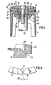
- the reciprocating piston essentially consists of a piston skirt 1 with a piston skirt 2, a piston skirt 3 with a top land 4, a centering sleeve 5 for radially fixing the two aforementioned piston main parts 1, 2 and 3, 4, one in an annular groove 6 of the top land 4 seated piston ring 7, a centering piece 8 with base plate 9 and from an end cover 10 with centering hub 11.
- a piston rod is designated, at each end of which there is a reciprocating piston (the second reciprocating piston is not shown), both of which are rigidly connected to the piston rod 12. This is done, for example, by a cap screw (13) which is screwed into the piston rod 12.
- the radial fixation of the reciprocating piston with respect to the piston rod 12 takes place by means of a snug fit 14 plate 9 on the piston rod 12.
- the base plate 9 in turn fixes with its centering piece 8 the centering hub 11 of the end cover 10.
- the two parts 8, 9 and 10, 11 are secured against rotation by a dowel pin 15 which with its inner end in the Piston rod 12 protrudes.
- the dowel pin 15 also forms a fuse for the cap screw 13.
- the piston skirt 1 with the piston skirt 2, the piston crown 3 with the top land 4, the spring-loaded piston ring 7, which has an expansion slot 16, and the centering sleeve 5 are all made of a ceramic material which is highly thermally stable and has good sliding properties .
- the piston ring 7 is provided with an arcuate rounded portion 17 for the arrangement of a torsion pin 18 which prevents the piston ring 7 from moving.
- a groove 19 is provided on the inner wall.
- a fillet 20 is incorporated on the piston crown 3 to avoid notch stresses.
- the top land 4 can be provided radially on the outside with a labyrinth seal in the form of rotational grooves 24 (FIG. 2).
- Piston shirt, piston ring and piston crown are made of ceramic.
- the piston crown can also be made from aluminum titanate.
- Excellent material for the piston ring is also silicon - infiltrated graphite (silicon carbide / graphite composite) or steel that has been coated with ceramic (eg zirconium oxide or silicon carbide). It is preferred if piston skirt (1) and piston crown (3) are made of the same material, or if (1) (3), piston ring (7) and centering sleeve (5) are made of the same material.
Landscapes
- Engineering & Computer Science (AREA)
- Chemical & Material Sciences (AREA)
- Combustion & Propulsion (AREA)
- Mechanical Engineering (AREA)
- General Engineering & Computer Science (AREA)
- Pistons, Piston Rings, And Cylinders (AREA)
Priority Applications (1)
| Application Number | Priority Date | Filing Date | Title |
|---|---|---|---|
| AT86104232T ATE53893T1 (de) | 1985-04-04 | 1986-03-27 | Mehrteiliger hubkolben fuer brennkraftmaschinen. |
Applications Claiming Priority (2)
| Application Number | Priority Date | Filing Date | Title |
|---|---|---|---|
| DE8510204U DE8510204U1 (de) | 1985-04-04 | 1985-04-04 | Mehrteiliger Hubkolben für Brennkraftmaschinen |
| DE8510204U | 1985-04-04 |
Publications (3)
| Publication Number | Publication Date |
|---|---|
| EP0197449A2 true EP0197449A2 (fr) | 1986-10-15 |
| EP0197449A3 EP0197449A3 (en) | 1987-11-25 |
| EP0197449B1 EP0197449B1 (fr) | 1990-05-02 |
Family
ID=6779583
Family Applications (1)
| Application Number | Title | Priority Date | Filing Date |
|---|---|---|---|
| EP86104232A Expired - Lifetime EP0197449B1 (fr) | 1985-04-04 | 1986-03-27 | Piston à plusieurs parties pour une machine à combustion interne |
Country Status (6)
| Country | Link |
|---|---|
| US (1) | US4751871A (fr) |
| EP (1) | EP0197449B1 (fr) |
| JP (1) | JPS61232366A (fr) |
| AT (1) | ATE53893T1 (fr) |
| CA (1) | CA1272645A (fr) |
| DE (2) | DE8510204U1 (fr) |
Cited By (1)
| Publication number | Priority date | Publication date | Assignee | Title |
|---|---|---|---|---|
| WO2012097893A1 (fr) * | 2011-01-21 | 2012-07-26 | Geist, Bertwin | Piston alternatif pour moteur à piston alternatif, et moteur à piston alternatif, et cylindre d'un moteur à piston alternatif |
Families Citing this family (18)
| Publication number | Priority date | Publication date | Assignee | Title |
|---|---|---|---|---|
| US4833977A (en) * | 1986-05-07 | 1989-05-30 | Volkswagen Ag | Piston for internal combustion engine |
| US4955284A (en) * | 1989-02-27 | 1990-09-11 | Ingersoll-Rand Company | Piston having ceramic parts |
| US4920864A (en) * | 1989-04-14 | 1990-05-01 | Jpi Transportation Products, Inc. | Reinforced piston |
| US5076150A (en) * | 1990-05-04 | 1991-12-31 | Dresser-Rand Company | Piston assembly with wear resistant piston ring lands |
| GB2246833B (en) * | 1990-06-23 | 1994-05-25 | T & N Technology Ltd | Pistons for engines or motors |
| DE4301860A1 (de) * | 1993-01-25 | 1994-09-22 | Stefan Dipl Phys Stock | Spezialkolben für Kolbenmaschinen |
| US5375567A (en) * | 1993-08-27 | 1994-12-27 | Lowi, Jr.; Alvin | Adiabatic, two-stroke cycle engine |
| US6044819A (en) * | 1996-03-06 | 2000-04-04 | The United States Of America As Represented By The Administrator Of The National Aeronautics And Space Administration | Pistons and cylinders made of carbon-carbon composite materials |
| US5713333A (en) * | 1996-10-21 | 1998-02-03 | Cummins Engine Company, Inc. | Wear-resistant fuel distributor rotor |
| JPH10292868A (ja) * | 1997-04-18 | 1998-11-04 | Honda Motor Co Ltd | 液体ポンプの軸封機構 |
| US20080289488A1 (en) * | 1999-04-01 | 2008-11-27 | Peter Robert Raffaele | Reciprocating fluid machines |
| US6076506A (en) * | 1998-05-20 | 2000-06-20 | Caterpillar Inc. | Piston for use in an engine |
| AUPR459501A0 (en) * | 2001-04-27 | 2001-05-24 | Raffaele, Michael John | Improvements in engines and components |
| DE102004018712B4 (de) * | 2004-04-17 | 2013-04-25 | Dr. Ing. H.C. F. Porsche Aktiengesellschaft | Kolben für eine Brennkraftmaschine |
| DE102004018714B4 (de) * | 2004-04-17 | 2013-04-25 | Dr. Ing. H.C. F. Porsche Aktiengesellschaft | Verfahren zur Herstellung eines Kolbens |
| EP1911952B1 (fr) * | 2006-10-11 | 2017-11-22 | Nissan Motor Co., Ltd. | Moteur à combustion interne |
| JP2010518312A (ja) * | 2007-02-14 | 2010-05-27 | アジレント・テクノロジーズ・インク | シリコンカーバイドピストンを備えているhplcポンプ装置及び/又は作動チャンバ |
| JP7313505B1 (ja) * | 2022-03-28 | 2023-07-24 | Tpr株式会社 | ピストンユニット、トップランド部材、及びピストンユニット用部品の組合せ |
Family Cites Families (17)
| Publication number | Priority date | Publication date | Assignee | Title |
|---|---|---|---|---|
| DE463748C (de) * | 1928-08-03 | Werke Kiel Akt Ges Deutsche | Mit Kuehleinsatz versehener Kolben fuer Brennkraftmaschinen | |
| GB119183A (en) * | 1918-02-11 | 1918-09-26 | Alphonse Soetens | Improvements in or relating to Pistons. |
| US1668672A (en) * | 1927-04-01 | 1928-05-08 | Charles W Darrah | Piston |
| US1956355A (en) * | 1931-02-18 | 1934-04-24 | Junkers Hugo | Internal combustion engine |
| US1963725A (en) * | 1933-09-08 | 1934-06-19 | Perfect Circle Co | Piston and piston ring |
| US2105950A (en) * | 1936-03-07 | 1938-01-18 | Ingersoll Rand Co | Piston |
| US2471477A (en) * | 1946-03-08 | 1949-05-31 | Air Liquide | Piston packing |
| US2657961A (en) * | 1950-03-15 | 1953-11-03 | Maschf Augsburg Nuernberg Ag | Piston for internal-combustion engines |
| DE920758C (de) * | 1951-12-21 | 1954-11-29 | Heinz Boerner | Zweitaktbrennkraftmaschine |
| US3136306A (en) * | 1961-04-20 | 1964-06-09 | Stevens Inst Technology | Piston for a high performance internal combustion engine |
| DE2212922B2 (de) * | 1972-03-17 | 1976-02-05 | Karl Schmidt Gmbh, 7107 Neckarsulm | Gebauter kolben fuer verbrennungskraftmaschinen |
| GB1439328A (en) * | 1972-07-28 | 1976-06-16 | Wellworthy Ltd | Pistons and piston rings |
| US4242948A (en) * | 1977-12-16 | 1981-01-06 | Cummins Engine Company, Inc. | Insulated composite piston |
| US4404935A (en) * | 1981-04-27 | 1983-09-20 | Kyocera International, Inc. | Ceramic capped piston |
| EP0088952B1 (fr) * | 1982-03-05 | 1986-05-28 | Feldmühle Aktiengesellschaft | Pièce de déplacement pour une pompe avec piston |
| DE3218320A1 (de) * | 1982-05-14 | 1983-11-17 | Ficht GmbH, 8011 Kirchseeon | Vorrichtung zum loesbaren befestigen der kolben an den kolbenstangen einer brennkraftmaschine |
| DE3301913C2 (de) * | 1983-01-21 | 1985-05-09 | Feldmühle AG, 4000 Düsseldorf | Kolbenring für eine Brennkraftmaschine |
-
1985
- 1985-04-04 DE DE8510204U patent/DE8510204U1/de not_active Expired
-
1986
- 1986-03-19 US US06/841,307 patent/US4751871A/en not_active Expired - Fee Related
- 1986-03-27 AT AT86104232T patent/ATE53893T1/de not_active IP Right Cessation
- 1986-03-27 EP EP86104232A patent/EP0197449B1/fr not_active Expired - Lifetime
- 1986-03-27 DE DE8686104232T patent/DE3670885D1/de not_active Expired - Fee Related
- 1986-04-03 JP JP61075683A patent/JPS61232366A/ja active Granted
- 1986-04-03 CA CA000505741A patent/CA1272645A/fr not_active Expired - Fee Related
Cited By (1)
| Publication number | Priority date | Publication date | Assignee | Title |
|---|---|---|---|---|
| WO2012097893A1 (fr) * | 2011-01-21 | 2012-07-26 | Geist, Bertwin | Piston alternatif pour moteur à piston alternatif, et moteur à piston alternatif, et cylindre d'un moteur à piston alternatif |
Also Published As
| Publication number | Publication date |
|---|---|
| EP0197449A3 (en) | 1987-11-25 |
| DE3670885D1 (de) | 1990-06-07 |
| JPS61232366A (ja) | 1986-10-16 |
| US4751871A (en) | 1988-06-21 |
| JPH0587672B2 (fr) | 1993-12-17 |
| ATE53893T1 (de) | 1990-06-15 |
| EP0197449B1 (fr) | 1990-05-02 |
| CA1272645A (fr) | 1990-08-14 |
| DE8510204U1 (de) | 1985-07-11 |
Similar Documents
| Publication | Publication Date | Title |
|---|---|---|
| EP0197449B1 (fr) | Piston à plusieurs parties pour une machine à combustion interne | |
| DE3134768C2 (de) | Kolbenzylinderaggregat für Brennkraftkolbenmaschinen, insbesondere für Otto- und Dieselmotoren | |
| DE3506069C2 (fr) | ||
| DE68910934T2 (de) | Kolben. | |
| EP0017279A1 (fr) | Piston en deux ou plusieurs parties pour moteurs à combustion interne | |
| DE2307347A1 (de) | Mehrteiliger tauchkolben fuer viertaktbrennkraftmaschinen, insbesondere grossdieselmotoren | |
| DE3885765T2 (de) | Brennkraftmaschine mit einem kolben, versehen mit einer hoch angeordneten ringnut. | |
| EP0007661B1 (fr) | Assemblage de piston de moteur à combustion interne comportant des moyens de refroidissement liquide | |
| EP0250790A1 (fr) | Machine à piston | |
| DE3543668A1 (de) | Zylinderlaufbuchse fuer hubkolben-verbrennungsmotoren | |
| DE3228616A1 (de) | Kolben fuer verbrennungsmotoren | |
| DE4203384C2 (de) | Kolben einer Kolbenmaschine | |
| DE3611165C2 (fr) | ||
| DE3249290T1 (de) | Zusammengesetzter kolben | |
| EP0166109A2 (fr) | Piston à plusieurs parties pour un moteur à combustion interne | |
| DE60006079T2 (de) | Freikolbenbrennkraftmaschine mit kolbenkopf und radial bewegbare kappe | |
| DE2333621A1 (de) | Rotorwickelkopfabstuetzung fuer schnelllaufende elektrische maschinen, insbesondere turbogenerator | |
| DE19605588C2 (de) | Verfahren zur Bearbeitung einer Zylinderlaufbahn bei Brennkraftmaschinen | |
| DE3214093A1 (de) | Kolben fuer verbrennungskraftmaschinen mit einem seine brennraumnahen wandteile abdeckenden einsatz | |
| DE3722437A1 (de) | Kolben-kolbenbolzenbaugruppe | |
| DE2410140A1 (de) | Leichtmetallkolben fuer brennkraftmaschinen | |
| DE3218320C2 (fr) | ||
| EP0775819A1 (fr) | Piston pour un moteur à combustion interne | |
| EP0225477A2 (fr) | Piston pour moteurs à combustion interne | |
| DE3742616A1 (de) | Einteiliger, leichter und reibungsarmer leichtmetallkolben fuer verbrennungsmotoren |
Legal Events
| Date | Code | Title | Description |
|---|---|---|---|
| PUAI | Public reference made under article 153(3) epc to a published international application that has entered the european phase |
Free format text: ORIGINAL CODE: 0009012 |
|
| AK | Designated contracting states |
Kind code of ref document: A2 Designated state(s): AT DE FR GB IT |
|
| PUAL | Search report despatched |
Free format text: ORIGINAL CODE: 0009013 |
|
| AK | Designated contracting states |
Kind code of ref document: A3 Designated state(s): AT DE FR GB IT |
|
| 17P | Request for examination filed |
Effective date: 19880220 |
|
| 17Q | First examination report despatched |
Effective date: 19890210 |
|
| GRAA | (expected) grant |
Free format text: ORIGINAL CODE: 0009210 |
|
| AK | Designated contracting states |
Kind code of ref document: B1 Designated state(s): AT DE FR GB IT |
|
| REF | Corresponds to: |
Ref document number: 53893 Country of ref document: AT Date of ref document: 19900615 Kind code of ref document: T |
|
| REF | Corresponds to: |
Ref document number: 3670885 Country of ref document: DE Date of ref document: 19900607 |
|
| ITF | It: translation for a ep patent filed | ||
| ET | Fr: translation filed | ||
| GBT | Gb: translation of ep patent filed (gb section 77(6)(a)/1977) | ||
| PLBE | No opposition filed within time limit |
Free format text: ORIGINAL CODE: 0009261 |
|
| STAA | Information on the status of an ep patent application or granted ep patent |
Free format text: STATUS: NO OPPOSITION FILED WITHIN TIME LIMIT |
|
| ITTA | It: last paid annual fee | ||
| 26N | No opposition filed | ||
| PGFP | Annual fee paid to national office [announced via postgrant information from national office to epo] |
Ref country code: DE Payment date: 19940518 Year of fee payment: 9 |
|
| PGFP | Annual fee paid to national office [announced via postgrant information from national office to epo] |
Ref country code: FR Payment date: 19950210 Year of fee payment: 10 |
|
| PGFP | Annual fee paid to national office [announced via postgrant information from national office to epo] |
Ref country code: GB Payment date: 19950214 Year of fee payment: 10 |
|
| PGFP | Annual fee paid to national office [announced via postgrant information from national office to epo] |
Ref country code: AT Payment date: 19950223 Year of fee payment: 10 |
|
| PG25 | Lapsed in a contracting state [announced via postgrant information from national office to epo] |
Ref country code: DE Effective date: 19951201 |
|
| PG25 | Lapsed in a contracting state [announced via postgrant information from national office to epo] |
Ref country code: GB Effective date: 19960327 Ref country code: AT Effective date: 19960327 |
|
| GBPC | Gb: european patent ceased through non-payment of renewal fee |
Effective date: 19960327 |
|
| PG25 | Lapsed in a contracting state [announced via postgrant information from national office to epo] |
Ref country code: FR Effective date: 19961129 |
|
| REG | Reference to a national code |
Ref country code: FR Ref legal event code: ST |
|
| PG25 | Lapsed in a contracting state [announced via postgrant information from national office to epo] |
Ref country code: IT Free format text: LAPSE BECAUSE OF NON-PAYMENT OF DUE FEES;WARNING: LAPSES OF ITALIAN PATENTS WITH EFFECTIVE DATE BEFORE 2007 MAY HAVE OCCURRED AT ANY TIME BEFORE 2007. THE CORRECT EFFECTIVE DATE MAY BE DIFFERENT FROM THE ONE RECORDED. Effective date: 20050327 |