EP0197455B1 - Verfahren zur Herstellung und Verwendung von cerierten Wolframelektroden - Google Patents
Verfahren zur Herstellung und Verwendung von cerierten Wolframelektroden Download PDFInfo
- Publication number
- EP0197455B1 EP0197455B1 EP86104274A EP86104274A EP0197455B1 EP 0197455 B1 EP0197455 B1 EP 0197455B1 EP 86104274 A EP86104274 A EP 86104274A EP 86104274 A EP86104274 A EP 86104274A EP 0197455 B1 EP0197455 B1 EP 0197455B1
- Authority
- EP
- European Patent Office
- Prior art keywords
- tungsten
- electrode
- bar
- arc
- furnace
- Prior art date
- Legal status (The legal status is an assumption and is not a legal conclusion. Google has not performed a legal analysis and makes no representation as to the accuracy of the status listed.)
- Expired - Lifetime
Links
- JJWOSYFQQOVUFV-UHFFFAOYSA-N NC1C=CC2C1C2 Chemical compound NC1C=CC2C1C2 JJWOSYFQQOVUFV-UHFFFAOYSA-N 0.000 description 1
Images

Classifications
-
- B—PERFORMING OPERATIONS; TRANSPORTING
- B23—MACHINE TOOLS; METAL-WORKING NOT OTHERWISE PROVIDED FOR
- B23K—SOLDERING OR UNSOLDERING; WELDING; CLADDING OR PLATING BY SOLDERING OR WELDING; CUTTING BY APPLYING HEAT LOCALLY, e.g. FLAME CUTTING; WORKING BY LASER BEAM
- B23K35/00—Rods, electrodes, materials, or media, for use in soldering, welding, or cutting
- B23K35/22—Rods, electrodes, materials, or media, for use in soldering, welding, or cutting characterised by the composition or nature of the material
- B23K35/222—Non-consumable electrodes
-
- B—PERFORMING OPERATIONS; TRANSPORTING
- B23—MACHINE TOOLS; METAL-WORKING NOT OTHERWISE PROVIDED FOR
- B23K—SOLDERING OR UNSOLDERING; WELDING; CLADDING OR PLATING BY SOLDERING OR WELDING; CUTTING BY APPLYING HEAT LOCALLY, e.g. FLAME CUTTING; WORKING BY LASER BEAM
- B23K35/00—Rods, electrodes, materials, or media, for use in soldering, welding, or cutting
- B23K35/40—Making wire or rods for soldering or welding
- B23K35/402—Non-consumable electrodes; C-electrodes
-
- Y—GENERAL TAGGING OF NEW TECHNOLOGICAL DEVELOPMENTS; GENERAL TAGGING OF CROSS-SECTIONAL TECHNOLOGIES SPANNING OVER SEVERAL SECTIONS OF THE IPC; TECHNICAL SUBJECTS COVERED BY FORMER USPC CROSS-REFERENCE ART COLLECTIONS [XRACs] AND DIGESTS
- Y10—TECHNICAL SUBJECTS COVERED BY FORMER USPC
- Y10T—TECHNICAL SUBJECTS COVERED BY FORMER US CLASSIFICATION
- Y10T428/00—Stock material or miscellaneous articles
- Y10T428/12—All metal or with adjacent metals
- Y10T428/12014—All metal or with adjacent metals having metal particles
- Y10T428/12028—Composite; i.e., plural, adjacent, spatially distinct metal components [e.g., layers, etc.]
- Y10T428/12063—Nonparticulate metal component
- Y10T428/12104—Particles discontinuous
- Y10T428/12111—Separated by nonmetal matrix or binder [e.g., welding electrode, etc.]
Definitions
- This invention proposes a non-consumable electrode material and a process for preparing a ceriated tungsten electrode material.
- the tungsten electrode material used in the inert gas shield arc welding contained (1-2%) thorium oxide as an additive.
- the addition of the thorium improved its contamination and its loss.
- the welding performance of arc inducing voltage and arc starting loss was much better than that of pure tungsten electrode material.
- the lifetime of the electrode was comparatively prolonged.
- the disadvantage was that of production of radioactive contamination surrounding the welding area, caused by the existence of the accompanied thorium and thorium oxide, which is harmful to human health.
- U.S. Patent 2,744,183 a kind of inert gas shield arc welding electrode material for "Inert Gas Shield Arc Welding" was proposed.
- Its main composition was tungsten containing 2-10% several kinds of additives, i.e. it contained at least 2 kinds of oxides selected from any of the barium oxide, calcium oxide, cerium oxide and yttrium oxide.
- 2,825,703,headed "Tungsten Arc Electrode” is proposed a kind of non-consumable inert gas shield arc welding electrode.
- the known electrode is composed mainly of tungsten with a small amount of about 0.01 - 0.30% cerium oxide as an additive. It was also pointed out that not too much of the additive should be added, for otherwise the material would become too brittle to be rotary forged.
- the present inventor had provided an opinion, and had it handed over by the Chinese Representative to ISO in 1980.
- the inventor by then, had proposed a ceriated tungsten material, composed of weight proportion of ⁇ 2% ceric oxide, and had suggested it to be listed into the ISO/TC Standard of "The Tungsten Electrodes For Inert Gas Welding and Plasma Welding and Cutting". And that was passed as a draft DP 6848 (no prior publication).
- the electrode material is subjected to rotary swaging and grinding to form a tungstencerium oxide electrode rod or the like.
- This material can be used as an electrode rod for TIG welding requiring high arc generating power and resistance to consumption and deformation as well as an electrode for common use.
- cerium nitrate solution is added and mixed to and with metallic W powder and the mixture is evaporated to dryness and thereafter the mixture is heated to 300 ⁇ 500°C in an H2 atmosphere to decompose the Ce compound.
- the Ce compound after the decomposition by heating is in succession subjected to a secondary reduction at 900 ⁇ 1,100°C and the intended W-cerium oxide powder is obtained.
- the Ce compound is a solution in a mixing stage according to such process for manufacturing the powder by wet type doping and therefore said solution sticks to the surface of the W particles and if the mixture is made into powder, the powder mixed extremely finely and uniformly with the cerium oxide particles is obtained.
- the object of this invention is to propose a special kind of tungsten electrode material doped with cerium oxide and its fabricating process, in order to solve the above mentioned technical problems; namely:
- the kind of non-consumable electrode material is a tungsten material, doped with cerium with a weight proportion of more than 3 and up to 4.5 % of cerium oxide.
- this invention proposes a process for preparing a ceriated tungsten electrode material containing cerium oxide in 1.0 up to 4.5 % by weight by powder metallurgy. In this way the brittleness existing in forging the material can be overcome.
- the details of the process according to the invention are: Calculate the weight percent of the cerium oxide needed to composite with tungsten trioxide and add the ceric salt into the tungsten trioxide.
- the salt solution is first evaporated to dryness and then calcinated.
- the composite powder is then reduced in a tubular furnace with hydrogen by two stages. The reduced ceriated tungsten composite powder is pressed into bar form ingot.
- the following technique parameters should be strictly controlled during the fabricating process:
- the amount of cerium oxide added to the tungsten trioxide should be calculated in such a way that only 88% of cerium oxide are needed in a ceriated tungsten electrode.
- the salt solution e.g. nitrate is prepared accordingly.
- the solution is then carefully doped into an evaporating vessel containing heated and agitated tungsten trioxide. After evaporation, it is dried and calcinated at a temperature of 300° - 800°C.
- the temperatures of the 2 stage reduction in hydrogen tubular furnace should firstly be held under 750°C, and secondly under 900°C.
- the maximum grain size of ceriated tungsten powder will be less than 8 ⁇ .
- the pressure required to press the bar is 1.5 - 3.5 ton/cm2.
- the highest presintering temperature for the molybdenum wired furnace with hydrogen is 1250°C.
- the bar should be covered with a lid piece. Then the bar should be sintered in bell-jar sintering furnace under hydrogen protection.
- the sintering current under the high temperature should not exceed 85% of that of the cut-off fuse current, and it may be accomplished in one stage or two stages.
- the rotary forging from the original ingot bar to 0 ⁇ 6.0 mm is carried out after it has been heated in a hydrogen protected molybdenum wired furnace.
- the rotary forging, from 0 ⁇ 6.0 mm to finishing is executed after it has been heated in a gas fired furnace.
- the rotary forging temperature range from original ingot bar to finishing is 1750°C-1200°C; the temperature may be decreased as the diameter is getting smaller.
- the annealing treatment should be added during the forging period.
- the furnace tube of the molybdenum wired furnace for the heating of the ingot bar for rotary forging should be subject to the coating treatment so that the difficulties effected in processing may be avoided.
- the heating temperature in the gas fired furnace for under 0 ⁇ 3.0 mm wire drawing ranges from 1300°C to 700°C, and it may be reduced as the wire diameter is getting smaller.
- This invention proposes various applicable scope of the ceriated tungsten material containing 1.0 - 4.5% cerium oxide and the technical performances obtained by the said material are all far superior to that of the thoriated tungsten material.
- the practicable experimental results have indicated that when the ceriated tungsten material was used in inert gas shield arc welding, hydrogen atomic welding, argon arc deposit welding and pulse argon arc welding, etc., the purity of the inert gas required would be lower than that of the thoriated tungsten material.
- the ceriated tungsten electrode When it was used in the inert gas shield arc welding, plasma welding, cutting, spray coating, smelting and all other applicable scope of plasma arc, the ceriated tungsten electrode would possess higher arc compression, arc stability, higher reliability in repeated arc inducing and allowable current density. It would also possess the property of lowering the inducing arc current required and enlarging the cutting off gap; moreover, the service life will be increased many times. Under the work condition of plasma arc welding, the end part of the electrode would possess "Natural Tapering" special feature; the welding passes would be narrower and more smooth; and the fusion pool would be deeper. Especially it is most suitable in the case of thin metal plate and long continuous welding.
- the cutting seam In the plasma cutting, the cutting seam would be narrower and more vertical, and smaller lag amount.
- the smoothness of the spray-coated surface When it was used in the plasma spray coating, the smoothness of the spray-coated surface would be enhanced and in the plasma smelting the continuous smelting time would be improved; when it was used for the laser transmitting light sources of pulse xenon lamp, high capacity pulse xenon lamp, high power pulse xenon lamp, high repeated frequency xenon lamp, low repeated frequency xenon lamp and short pulse krypton lamp, there would be no leaking flash occurence, and their service lifetime would be increased many times over.
- Fig. 1 shows the comparison of compression degree of electrode arc zones set by the ceriated tungsten electrode material and thoriated tungsten electrode material.
- the right fig. arc zone is set by the ceriated tungsten electrode, while the left fig. arc zone is set by the thoriated tungsten electrode.
- 1 is electrode
- 2 is bright zone. From the figure it can be seen clearly that the ceriated tungsten has a narrower bright zone.
- the testing conditions were: The electrical source was direct current of positive polarity and the end shape of the electrode was flat, the inside diameter of the nozzle was 0 ⁇ 14 mm and the length of electrode extended over the nozzle was 7 mm; the anode used was water cooled braze anode, and the distance between the poles was 3.5 mm; the argon flow was 10 l/hr., the idling voltage was 65V; the induced arc was high frequency triggered; the distance between the welding gun and anode was vertically secured. Each arc inducing test was counted as once, when the arc, induced under test was maintained 2 minutes and cut off for 2 minutes (four minutes for once).
- the arc could be re-established only after 3-4 times pressing with high frequency, but the arc was still irregular in aspect.
- the arc inducing was more difficult after 34 times, but it became regular after 40 times and its shape and aspect recovered normally. 5. Comparative Tests of Arc Welding Fusion Zone Depth.
- the test conditions were: The arc welding tests were carried out with positive polarity on a same stainless steel plate of 8 mm thickness. The welding rod was not used during tests. The steel plate sample was water cooled each time after the electrode material had finished every test, so that other kind of electrode material could be tested subsequently.
- the inside diameter of the nozzle was 0 ⁇ 14 mm and the distance between poles was 2 mm.
- the testing current was 255A and the test voltage was 19.5V.
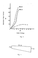
- Electrode material 2%Th-W 2%Ce-W 4%Ce-W Electrode diameter 0 ⁇ 4.0 mm 0 ⁇ 4.0 mm 0 ⁇ 4.0 mm Stability of welding arc strictly agitating stable stable Sectional Depth of arc welding fusion zone see Fig.2 left side fusion depth see Fig.2 medium fusion depth see Fig.2 right side fusion depth 6.
- the workpiece used in testing was 16 mm thick stainless plate (1Cr18Ni9Ti), and the diameter of the testing electrode was 5.2 mm.
- the idling voltage was 250V and cutting current was 250A.
- the test results had shown that for 2%Th-W electrode, the consumption of electrode was 0.6 g after cutting a length of 3 meters; for 3 % Ce-W electrode, the consumption of electrode was 0.31 gram after cutting a length of 18 meters.
- the shapes of electrodes before and after cutting was shown in Fig.
- the uprising speed of testing current and cutting speed were as follows: Test results: Electrode material 2%Th-W 2%Ce-W 4%Ce-W Electrode diameter 5.0 mm 5.0 mm 5.0 mm "Double Arc" current occured A 400A occured after cutting 260 mm long 450A not occured after cutting 500 mm long 450A not occured after cutting 500 mm long 450A not occured after cutting 500 mm long The burnt off diameter of tip point of electrode after test mm 0 ⁇ 2.6 0 ⁇ 1.9 0 ⁇ 1.6 9. Comparative Tests of Cutting Depth, Welding Width and Lag Amount of Plasma Cutting: (The cutting depth listed herein is the cutting depth which is not cut-off penetrated through the workpiece).
- the purity of N2 should be 99.9 %, and that of H2 should be 98 %; nozzle 0 ⁇ 8 x 32 mm; electrode 0 ⁇ 7.8 mm, electrode protruded length 21 mm; electrode distance apart 2 mm; high frequency inducing arc (argon flow 500 l/hr); the arc test did not spray powder, current 400 A; power 28 Kw.
- the gas flow rate of N2 was 2500 l/hr, and that of H2 was 600 l/hr.
- the testing time was 20 minutes and temperature of inlet water was 18°C.
- Test results The test results have indicated that the output energy of the laser transmitting device decreased many times over (due to the electrode spattering) after the 2%Th-W electrode had been used over 300,000 times; while the same device, made by 2%Ce-W electrode only dropped 4 - 12 % after 10,000,000 times of usage, so the limit of service lifetime was much higher than that of the Th-W electrode, and moreover its light efficiency increased by 10 - 15 %. 12. Comparative Tests of Starting Voltages Used in Repeated Frequency Xenon Lamp. Test condition: lamp tube 0 ⁇ 3.2 x 27 x 51 mm, electrode 0 ⁇ 2.0 mm, output energy 1.2 Joule, using repeated frequency.
Landscapes
- Engineering & Computer Science (AREA)
- Mechanical Engineering (AREA)
- Powder Metallurgy (AREA)
- Electrical Discharge Machining, Electrochemical Machining, And Combined Machining (AREA)
- Chemical Vapour Deposition (AREA)
- Discharge Lamp (AREA)
- Compounds Of Alkaline-Earth Elements, Aluminum Or Rare-Earth Metals (AREA)
- Arc Welding In General (AREA)
Claims (5)
- Material für eine nichtabschmelzende Elektrode auf der Basis von mit einem Metall dotiertem Wolfram, dadurch gekennzeichnet, daß es als Dotierstoff Cer bei einem Gewichtsanteil von über 3 und bis zu 4,5 % Ceroxid enthält.
- Verfahren zur pulvermetallurgischen Herstellung eines Materials für eine Elektrode aus ceriertem Wolfram mit 1,0 bis 4,5 Gew.-% Ceroxid, dadurch gekennzeichnet, daß man Wolframtrioxid eine Cersalzlösung zusetzt, das erhaltene Produkt trocknet und bei 300 bis 800°C glüht, in einem Wasserstoff-Rohrofen in zwei Stufen reduziert, wobei die erste Stufe bei 750°C und die zweite bei 900°C durchgeführt werden, die maximale Korngröße des auf diese Weise erhaltenen Wolframpulvers unter 8 µm liegt, das erhaltene Wolfram-Cer-Pulver zu einer Stange verpreßt und in einem Molybdänofen unter Durchleiten von Wasserstoff vorsintert, die Stange dann bei hoher Temperatur elektrisch und unter Wasserstoffschutz sintert, die Stange einer Warmdrehverformung unterzieht und gegebenenfalls während der Verformung glüht, im gasbeheizten Ofen bis zu einem Durchmesser von unter 3,00 mm zieht, bis man einen Draht mit dem gewünschten Durchmesser erhält, und gegebenenfalls während des Ziehens glüht.
- Verfahren nach Anspruch 2, worin der Druck für das Pressen der Stange bei 1,5 bis 3,5 t/cm² gehalten wird, die Vorsintertemperatur 1100 bis 1250°C beträgt und die Stange während des Vorsinterns mit einer Abdeckung versehen sein muß.
- Verfahren nach einem der Ansprüche 2 bis 3, worin der Strom für die erwähnte Sinterung bei hoher Temperatur nicht über 85 % des Stroms für die Abschaltung des Schmelzvorgangs liegen darf und das Verfahren ein- oder zweistufig durchgeführt werden kann.
- Verfahren nach einem der Ansprüche 2 bis 4, worin der Temperaturbereich für die Warmdrehverformung 1750 bis 1200°C beträgt, die Temperatur für die Drehverformung vom Vierkantstab bis zu einer Stange mit einem Durchmesser von 3,00 mm allmählich mit dem langsam abnehmenden Durchmesser der geschmiedeten Stange abgesenkt wird, während der Drehverformung ein Glühvorgang erforderlich ist, die Drehverformung des Vierkantstabes in einem Ofen mit Molybdänheizdrähten durchgeführt wird, das Rohr dieses Ofens vorgängig in geeigneter Weise beschichtet werden muß, das Ziehen bis zu einem Stabdurchmesser von unter 3,00 mm in einem gasbeheizten Ofen in einem Temperaturbereich von 1300 bis 700°C durchgeführt werden muß und die Temperatur mit abnehmendem Drahtdurchmesser abgesenkt wird.
Priority Applications (1)
| Application Number | Priority Date | Filing Date | Title |
|---|---|---|---|
| AT86104274T ATE78741T1 (de) | 1985-04-01 | 1986-03-27 | Verfahren zur herstellung und verwendung von cerierten wolframelektroden. |
Applications Claiming Priority (2)
| Application Number | Priority Date | Filing Date | Title |
|---|---|---|---|
| CN85100484 | 1985-04-01 | ||
| CN85100484.9A CN1005732B (zh) | 1985-04-01 | 1985-04-01 | 钨铈电极材料及其制备工艺和用途 |
Publications (3)
| Publication Number | Publication Date |
|---|---|
| EP0197455A2 EP0197455A2 (de) | 1986-10-15 |
| EP0197455A3 EP0197455A3 (en) | 1988-08-31 |
| EP0197455B1 true EP0197455B1 (de) | 1992-07-29 |
Family
ID=4791197
Family Applications (1)
| Application Number | Title | Priority Date | Filing Date |
|---|---|---|---|
| EP86104274A Expired - Lifetime EP0197455B1 (de) | 1985-04-01 | 1986-03-27 | Verfahren zur Herstellung und Verwendung von cerierten Wolframelektroden |
Country Status (6)
| Country | Link |
|---|---|
| US (1) | US4678718A (de) |
| EP (1) | EP0197455B1 (de) |
| JP (1) | JPS61288044A (de) |
| CN (1) | CN1005732B (de) |
| AT (1) | ATE78741T1 (de) |
| DE (1) | DE3686190T2 (de) |
Families Citing this family (21)
| Publication number | Priority date | Publication date | Assignee | Title |
|---|---|---|---|---|
| DE3884653T2 (de) * | 1987-04-03 | 1994-02-03 | Fujitsu Ltd | Verfahren und Vorrichtung zur Gasphasenabscheidung von Diamant. |
| US5194218A (en) * | 1988-08-18 | 1993-03-16 | The United States Of America As Represented By The United States Department Of Energy | Tungsten-yttria carbide coating for conveying copper |
| US4859239A (en) * | 1988-12-20 | 1989-08-22 | Gte Products Corporation | Tungsten electrode and method of producing same |
| US5096663A (en) * | 1990-05-29 | 1992-03-17 | Auburn University | Method of optimizing composite preparation for electrical properties: maximum capacitance electrodes |
| US5159174A (en) * | 1990-11-01 | 1992-10-27 | Westinghouse Electric Corp. | Nonconsumable electrode for stainless steel welding and method of welding |
| US5123868A (en) * | 1991-04-17 | 1992-06-23 | John F. Waymouth Intellectual Property And Education Trust | Electromagnetic radiators and process of making electromagnetic radiators |
| US5284614A (en) * | 1992-06-01 | 1994-02-08 | General Electric Company | Method of forming fine dispersion of ceria in tungsten |
| EP0606491A1 (de) * | 1992-07-31 | 1994-07-20 | Toho Kinzoku Co., Ltd. | Wolframelektrodenmaterial |
| JPH06297190A (ja) * | 1993-04-14 | 1994-10-25 | Toho Kinzoku Kk | タングステン電極材料 |
| DE4442161C1 (de) * | 1994-11-27 | 1996-03-07 | Bayerische Metallwerke Gmbh | Verfahren zur Herstellung eines Formteils |
| ES2117460T3 (es) * | 1995-03-24 | 1998-08-01 | Siemens Ag | Electrodo de emision, compuesto de un cuerpo portador que lleva una masa sinterizada en fusion, que favorece la emision de electrones. |
| US8420974B2 (en) * | 1997-03-20 | 2013-04-16 | Tadahiro Ohmi | Long life welding electrode and its fixing structure, welding head, and welding method |
| US20050155680A1 (en) * | 2004-01-16 | 2005-07-21 | Gyorgy Nagy | High ductility, high hot tensile strength tungsten wire and method of manufacture |
| JP4916264B2 (ja) * | 2006-09-20 | 2012-04-11 | 日本タングステン株式会社 | ヒュージング溶接用電極 |
| JP2007223036A (ja) * | 2007-03-26 | 2007-09-06 | Allied Material Corp | Cu−Wパイプとその製造方法及びそれを用いた放電加工用パイプ電極とその製造方法 |
| CN103378534A (zh) * | 2012-04-18 | 2013-10-30 | 靖江市神久机械制造有限公司 | 一种二氧化碳激光器放电装置 |
| US9646729B2 (en) * | 2013-01-18 | 2017-05-09 | Westinghouse Electric Company Llc | Laser sintering systems and methods for remote manufacture of high density pellets containing highly radioactive elements |
| CN105695833A (zh) * | 2016-04-12 | 2016-06-22 | 唐岁寒 | 一种电缆支持架 |
| CN106848333B (zh) * | 2017-02-22 | 2019-07-02 | 长沙理工大学 | 一种氧化铈负载三维镍铜合金多孔复合阴极的制备方法 |
| CN117888013B (zh) * | 2023-12-26 | 2025-07-08 | 厦门虹鹭钨钼工业有限公司 | 一种钨合金线材及其制备方法和应用 |
| CN121360818B (zh) * | 2025-12-22 | 2026-03-24 | 崇义章源钨业股份有限公司 | 一种钨铈合金丝及其制备方法 |
Family Cites Families (12)
| Publication number | Priority date | Publication date | Assignee | Title |
|---|---|---|---|---|
| US2744183A (en) * | 1952-11-13 | 1956-05-01 | Union Carbide & Carbon Corp | Inert gas-shielded arc welding |
| US2825703A (en) * | 1955-12-06 | 1958-03-04 | Union Carbide Corp | Tungsten arc electrode |
| US3169861A (en) * | 1961-08-16 | 1965-02-16 | Westinghouse Electric Corp | Method for making welding electrodes |
| US3434830A (en) * | 1965-10-22 | 1969-03-25 | Nicholas J Grant | Dispersion strengthening of metals and alloys |
| US3475159A (en) * | 1967-01-16 | 1969-10-28 | Dow Chemical Co | Method for preparing tungsten powders doped with refractory metal oxides |
| JPS551962B2 (de) * | 1973-07-27 | 1980-01-17 | ||
| JPS5315449A (en) * | 1976-07-29 | 1978-02-13 | Daiichi Tanpaku Kk | Bread composition |
| GB1446507A (en) * | 1978-09-15 | 1976-08-18 | V N I Pk I T I Elektrosvarochn | Electrode for plasma arc working of conductive materials |
| US4213027A (en) * | 1979-03-06 | 1980-07-15 | Vsesojuzny Nauchno-Issledovatelsky Proektno-Konstruktorsky i Teknologichesky Institut Elektrosvarochnogo Oborudovania | Method of treating electrodes intended for operation in argon as cathodes of an electric arc |
| JPS5741336A (en) * | 1980-08-27 | 1982-03-08 | Hitachi Ltd | Manufacture of thorium-tungsten |
| JPS59143041A (ja) * | 1983-02-04 | 1984-08-16 | Nippon Tungsten Co Ltd | タングステン電極材料 |
| JPS59170206A (ja) * | 1983-03-14 | 1984-09-26 | Nippon Tungsten Co Ltd | タングステン−酸化セリウム粉末の製造法 |
-
1985
- 1985-04-01 CN CN85100484.9A patent/CN1005732B/zh not_active Expired
- 1985-09-03 US US06/771,743 patent/US4678718A/en not_active Expired - Fee Related
-
1986
- 1986-03-27 EP EP86104274A patent/EP0197455B1/de not_active Expired - Lifetime
- 1986-03-27 JP JP61069716A patent/JPS61288044A/ja active Pending
- 1986-03-27 DE DE8686104274T patent/DE3686190T2/de not_active Expired - Fee Related
- 1986-03-27 AT AT86104274T patent/ATE78741T1/de not_active IP Right Cessation
Also Published As
| Publication number | Publication date |
|---|---|
| CN1005732B (zh) | 1989-11-08 |
| EP0197455A3 (en) | 1988-08-31 |
| JPS61288044A (ja) | 1986-12-18 |
| EP0197455A2 (de) | 1986-10-15 |
| ATE78741T1 (de) | 1992-08-15 |
| DE3686190T2 (de) | 1993-03-04 |
| US4678718A (en) | 1987-07-07 |
| DE3686190D1 (de) | 1992-09-03 |
| CN85100484A (zh) | 1986-08-13 |
Similar Documents
| Publication | Publication Date | Title |
|---|---|---|
| US4678718A (en) | Process and usage of ceriated tungsten electrode material | |
| US3930139A (en) | Nonconsumable electrode for oxygen arc working | |
| EP0248977B1 (de) | Elektrisches Anzündelement und Verfahren zu seiner Herstellung | |
| US5774780A (en) | Process for production of a shaped part | |
| DE1515230B1 (de) | Nichtabschmelzende Elektrode für Lichtbogen-Arbeitsvorgänge | |
| DE69123183T2 (de) | Verbundmaterial aus Silber- oder Silber-Kupferlegierung mit Metalloxyden und Verfahren zu seiner Herstellung | |
| JPH01127228A (ja) | 放電加工電極の製造法および放電加工電極 | |
| DE2919084C2 (de) | Nicht abschmelzende Elektrode zum Plasmaschweißen und Verfahren zur Herstellung dieser Elektrode | |
| DE2245717A1 (de) | Elektrode mit einem poroesen sinterkoerper | |
| EP0691673A2 (de) | Elektrischer Leiter in Lampen | |
| US5028756A (en) | Electrode wire for electric spark cutting | |
| US3231332A (en) | Electrodes for electric discharge apparatus | |
| EP0907960B1 (de) | Kalte elektrode für gasentladungen | |
| DE1806856B2 (de) | Verfahren zum umhuellen einer elektrodenspitze | |
| US4038579A (en) | Solder joint connection between lead-in conductor and electrode | |
| US4392047A (en) | Non-consumable electrode | |
| JP2577887B2 (ja) | タングステン電極材料 | |
| DE3519163C2 (de) | ||
| JPH11273618A (ja) | 放電電極材料及びその製造方法 | |
| CN100446898C (zh) | 多元复合稀土钨电子发射体的烧结方法 | |
| EP0651066A1 (de) | Material für wolframelektrode | |
| US2695945A (en) | Refractory metal electrode for inert gas-shielded arc welding | |
| JPH0691391A (ja) | タングステン電極材料 | |
| US5124528A (en) | Gas tungsten and plasma arc welding electrode having a carbide emitter end | |
| DE3817145C2 (de) | Elektrode für gepulste Gas-Laser und ihre Verwendung |
Legal Events
| Date | Code | Title | Description |
|---|---|---|---|
| PUAI | Public reference made under article 153(3) epc to a published international application that has entered the european phase |
Free format text: ORIGINAL CODE: 0009012 |
|
| AK | Designated contracting states |
Kind code of ref document: A2 Designated state(s): AT CH DE FR GB IT LI SE |
|
| 17P | Request for examination filed |
Effective date: 19870114 |
|
| PUAL | Search report despatched |
Free format text: ORIGINAL CODE: 0009013 |
|
| AK | Designated contracting states |
Kind code of ref document: A3 Designated state(s): AT CH DE FR GB IT LI SE |
|
| 17Q | First examination report despatched |
Effective date: 19900709 |
|
| ITF | It: translation for a ep patent filed | ||
| GRAA | (expected) grant |
Free format text: ORIGINAL CODE: 0009210 |
|
| AK | Designated contracting states |
Kind code of ref document: B1 Designated state(s): AT CH DE FR GB IT LI SE |
|
| REF | Corresponds to: |
Ref document number: 78741 Country of ref document: AT Date of ref document: 19920815 Kind code of ref document: T |
|
| REF | Corresponds to: |
Ref document number: 3686190 Country of ref document: DE Date of ref document: 19920903 |
|
| ET | Fr: translation filed | ||
| PLBE | No opposition filed within time limit |
Free format text: ORIGINAL CODE: 0009261 |
|
| STAA | Information on the status of an ep patent application or granted ep patent |
Free format text: STATUS: NO OPPOSITION FILED WITHIN TIME LIMIT |
|
| 26N | No opposition filed | ||
| EAL | Se: european patent in force in sweden |
Ref document number: 86104274.5 |
|
| PGFP | Annual fee paid to national office [announced via postgrant information from national office to epo] |
Ref country code: GB Payment date: 19950327 Year of fee payment: 10 |
|
| PGFP | Annual fee paid to national office [announced via postgrant information from national office to epo] |
Ref country code: SE Payment date: 19950328 Year of fee payment: 10 |
|
| PGFP | Annual fee paid to national office [announced via postgrant information from national office to epo] |
Ref country code: FR Payment date: 19950331 Year of fee payment: 10 Ref country code: AT Payment date: 19950331 Year of fee payment: 10 |
|
| PGFP | Annual fee paid to national office [announced via postgrant information from national office to epo] |
Ref country code: CH Payment date: 19950403 Year of fee payment: 10 |
|
| PGFP | Annual fee paid to national office [announced via postgrant information from national office to epo] |
Ref country code: DE Payment date: 19950530 Year of fee payment: 10 |
|
| PG25 | Lapsed in a contracting state [announced via postgrant information from national office to epo] |
Ref country code: GB Effective date: 19960327 Ref country code: AT Effective date: 19960327 |
|
| PG25 | Lapsed in a contracting state [announced via postgrant information from national office to epo] |
Ref country code: SE Effective date: 19960328 |
|
| PG25 | Lapsed in a contracting state [announced via postgrant information from national office to epo] |
Ref country code: LI Effective date: 19960331 Ref country code: CH Effective date: 19960331 |
|
| REG | Reference to a national code |
Ref country code: CH Ref legal event code: PL |
|
| GBPC | Gb: european patent ceased through non-payment of renewal fee |
Effective date: 19960327 |
|
| PG25 | Lapsed in a contracting state [announced via postgrant information from national office to epo] |
Ref country code: FR Effective date: 19961129 |
|
| PG25 | Lapsed in a contracting state [announced via postgrant information from national office to epo] |
Ref country code: DE Effective date: 19961203 |
|
| EUG | Se: european patent has lapsed |
Ref document number: 86104274.5 |
|
| REG | Reference to a national code |
Ref country code: FR Ref legal event code: ST |
|
| PG25 | Lapsed in a contracting state [announced via postgrant information from national office to epo] |
Ref country code: IT Free format text: LAPSE BECAUSE OF NON-PAYMENT OF DUE FEES;WARNING: LAPSES OF ITALIAN PATENTS WITH EFFECTIVE DATE BEFORE 2007 MAY HAVE OCCURRED AT ANY TIME BEFORE 2007. THE CORRECT EFFECTIVE DATE MAY BE DIFFERENT FROM THE ONE RECORDED. Effective date: 20050327 |