EP0197476A2 - Mikrowellen-Zirkulator - Google Patents
Mikrowellen-Zirkulator Download PDFInfo
- Publication number
- EP0197476A2 EP0197476A2 EP86104356A EP86104356A EP0197476A2 EP 0197476 A2 EP0197476 A2 EP 0197476A2 EP 86104356 A EP86104356 A EP 86104356A EP 86104356 A EP86104356 A EP 86104356A EP 0197476 A2 EP0197476 A2 EP 0197476A2
- Authority
- EP
- European Patent Office
- Prior art keywords
- substrate
- recess
- metal plate
- disc
- microwave circulator
- Prior art date
- Legal status (The legal status is an assumption and is not a legal conclusion. Google has not performed a legal analysis and makes no representation as to the accuracy of the status listed.)
- Granted
Links
Images
Classifications
-
- H—ELECTRICITY
- H01—ELECTRIC ELEMENTS
- H01P—WAVEGUIDES; RESONATORS, LINES, OR OTHER DEVICES OF THE WAVEGUIDE TYPE
- H01P1/00—Auxiliary devices
- H01P1/32—Non-reciprocal transmission devices
- H01P1/38—Circulators
- H01P1/383—Junction circulators, e.g. Y-circulators
- H01P1/387—Strip line circulators
Definitions
- the present invention relates to a microwave circulator, consisting of a dielectric substrate carrying a stripline branch and a ferrite disc, which is inserted into a recess which partially penetrates the substrate below the stripline branch.
- Such a microwave circulator is known from IEEE Transactions on Magnetics, Vol. Mag-11, No. 5, September 1975, pages 1273-1275.
- the ferrite disc completely fills the substrate recess and is flush with the underside of the substrate.
- the underside of the substrate is provided with a metallization serving as a ground line.
- the ferrite disc is metallized on the underside and there e.g. electrically connected to the metallization of the substrate by soldering.
- the metallization of the ferrite disc and the soldering of the ferrite and substrate metallization make the manufacturing process of a microwave circulator complex and expensive.
- the invention is therefore based on the object of specifying a microwave circulator of the type mentioned at the outset, which can be implemented with as little effort as possible.
- this object is achieved in that the substrate with its side opposite the strip line branch is applied to a metal plate, that the metal plate has a continuous bore, in which the ferrite disk protruding into the recess of the substrate continues, and that the bore opening on the the side of the metal plate opposite the substrate is covered by an electrically conductive disk which can be connected to the metal plate.
- the microwave circulator according to the invention also has very good electrical properties.
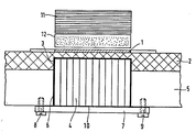
- the figure shows a section through a microwave circulator according to the invention.
- a dielectric substrate 2 which is not made of ceramic (aluminum oxide) as usual, but made of a soft material, e.g. a polytetrafluoroethylene ceramic compound, which are also known under the trade names such as RT-Duroid or DI-Clad.
- a soft material e.g. a polytetrafluoroethylene ceramic compound, which are also known under the trade names such as RT-Duroid or DI-Clad.
- Such substrate materials are much easier to machine than hard ceramic materials, which has a particularly favorable effect when machining the recess 3 in the substrate.
- the recess 3 is located below the strip line junction 1 applied to the top of the substrate 2.
- a ferrite disc 4 is inserted into the recess 3, the depth of which is less than the substrate thickness, and partially protrudes from the recess 3.
- a metal plate 5 (for example made of aluminum) serves as a carrier for the substrate 2 and as a ground line for the strip line structure 1 located on the upper side of the substrate.
- a bore 6 is provided which serves to receive the part of the ferrite disc 4 which protrudes from the substrate recess 3.
- the bore opening on the side (bottom side) of the metal plate 5 opposite the substrate 2 is covered with an electrically conductive disc 7, as a result of which the ferrite disc 4 is held in the bore 6 and the recess 3.
- the disc 7 is electrically contacted with the metal plate 5 by means of screws 8 and 9.
- An electrically conductive metal foil 10 placed between the disc 7, the metal plate 5 and the ferrite disc 4 improves the galvanic contact of the disc 7 with the metal plate 5 and serves to compensate for any difference between the thickness of the ferrite disc 4 and the depth of the recess 3 and hole 6.
- the impedance of the strip line junction 1 can be varied as a function of the ferrite disc thickness and can thus be set to a desired value.
- the stability of the thin substrate area present above the recess 3 can be improved in that the ferrite disc 4 is glued into the recess 3.
- a dielectric filler introduced into the recess 3 between the ferrite disc 4 and the substrate 2 avoids the formation of an air gap.
- the static magnetic field required for the circulator is generated by a permanent magnet 11 arranged above the stripline structure 1, which is glued to a metallic or dielectric spacer 12 in the exemplary embodiment shown.
- a permanent magnet 11 arranged above the stripline structure 1, which is glued to a metallic or dielectric spacer 12 in the exemplary embodiment shown.
- other known magnet systems can also be used.
- the microwave circulator described above can be produced with little effort because no metallization of the ferrite disc and no soldering to the substrate ground surface is required and an easily machinable substrate made of soft material is used.
- An exemplary embodiment of a circulator according to the invention with an RT-Duroid 6010 substrate of 635 ⁇ m thickness, a recess of approx. 300 ⁇ m depth embedded therein and a metal plate of approx. 3 mm thickness has a frequency bandwidth of ⁇ 20% at an operating frequency of 4 GHz. , a transmission loss of ⁇ 0.3 dB, a blocking loss of ⁇ 20 dB and an input standing wave ratio of ⁇ 1.2.
Landscapes
- Non-Reversible Transmitting Devices (AREA)
- Constitution Of High-Frequency Heating (AREA)
Abstract
Description
- Die vorliegende Erfindung betrifft eine Mikrowellen-Zirkulator, bestehend aus einem eine Streifenleitungsverzweigung tragenden dielektrischen Substrat und einer Ferritscheibe, welche in eine das Substrat teilweise durchsetzenden Aussparung unterhalb der Streifenleitungsverzweigung eingesetzt ist.
- Ein derartiger Mikrowellen-Zirkulator ist aus IEEE Transactions on Magnetics, Vol. Mag-11, No. 5, September 1975, Seiten 1273 - 1275 bekannt. Dabei füllt die Ferritscheibe die Substrataussparung vollständig aus und schließt mit der Unterseite des Substrats plan ab. Die Substratunterseite ist mit einer als Masseleitung dienenden Metallisierung versehen. Zur Gewährleistung einer homogenen, störungsfreien Masseübergabe zwischen der Metallisierung des Substrats und der Ferritscheibe ist die Ferritscheibe an der Unterseite metallisiert und dort z.B. durch Verlöten mit der Metallisierung des Substrats elektrisch verbunden. Die Metallisierung der Ferritscheibe und das Verlöten der Ferrit- und Substratmetallisierung machen das Herstellungsverfahren eines Mikrowellen-Zirkulators aufwendig und teuer.
- Der Erfindung liegt daher die Aufgabe zugrunde, einen Mikrowellen-Zirkulator der eingangs genannten Art anzugeben, der mit möglichst geringem Aufwand realisiert werden kann.
- Erfindungsgemäß wird diese Aufgabe dadurch gelöst, daß das Substrat mit seiner der Streifenleitungsverzweigung gegenüberliegenden Seite auf einer Metallplatte aufgebracht ist, daß die Metallplatte eine durchgehende Bohrung besitzt, worin sich die in die Aussparung des Substrats hineinragende Ferritscheibe fortsetzt, und daß die Bohrungsöffung auf der dem Substrat gegenüberliegenden Seite der Metallplatte von einer mit der Metallplatte verbindbaren elektrisch leitenden Scheibe abgedeckt ist.
- Zweckmäßige Ausführungen der Erfindung gehen aus den Unteransprüchen hervor.
- Der erfindungsgemäße Mikrowellen-Zirkulator besitzt neben dem Vorteil einer einfach durchzuführenden Montage auch sehr gute elektrische Eigenschaften.
- An Hand eines in der Zeichnung dargestellten Ausführungsbeispiels wird nun die Erfindung näher erläutert.
- Die Figur zeigt einen Schnitt durch einen Mikrowellen-Zirkulator gemäß der Erfindung.
- Als Träger für die Streifenleitungsverzweigung 1 dient ein dielektrisches Substrat 2, welches nicht wie sonst üblich aus Keramik (Aluminiumoxyd), sondern aus einem weichen Material z.B. einer Polytetrafluorethylen-Keramik-Verbindung, die auch unter den Handelsnamen wie RT-Duroid oder DI-Clad bekannt sind, besteht. Derartige Substratmaterialien sind wesentlich leichter zu bearbeiten als harte Keramikmaterialien, was sich besonders günstig bei der Bearbeitung der Aussparung 3 in dem Substrat auswirkt.
- Die Aussparung 3 befindet sich unterhalb der auf der Oberseite des Substrats 2 aufgebrachten Streifenleitungsverzweigung 1. In die Aussparung 3, deren Tiefe geringer als die Substratdicke ist, wird eine Ferritscheibe 4 eingesetzt, die zum Teil aus der Aussparung 3 herausragt.
- Als Träger für das Substrat 2 und als Masseleitung für die auf der Substratoberseite befindliche Streifenleitungsstruktur 1 dient eine Metallplatte 5 (z.B. aus Aluminium). In dieser Metallplatte 5 ist eine Bohrung 6 vorgesehen, die zur Aufnahme des aus der Substrataussparung 3 herausragenden Teils der Ferritscheibe 4 dient.
- Die Bohrungsöffnung an der dem Substrat 2 gegenüberliegenden Seite (Unterseite) der Metallplatte 5 ist mit einer elektrisch leitenden Scheibe 7 abgedeckt, wodurch die Ferritscheibe 4 in der Bohrung 6 und der Aussparung 3 gehalten wird. Um die Masseleitung unterhalb der Ferritscheibe 4 fortzusetzen, ist die Scheibe 7 mit der Metallplatte 5 mittels Schrauben 8 und 9 elektrisch kontaktiert. Eine zwischen die Scheibe 7, die Metallplatte 5 und die Ferritscheibe 4 gelegte elektrisch leitende Metallfolie 10 verbessert den galvanischen Kontakt der Scheibe 7 mit der Metallplatte 5 und dient als Ausgleich für eine eventuell vorhandene Differenz zwischen der Dicke der Ferritscheibe 4 und der Tiefe der Aussparung 3 und Bohrung 6.
- Die Impedanz der Streifenleitungsverzweigung 1 läßt sich in Abhängigkeit der Ferritscheibendicke variieren und somit auf einen gewünschten Wert einstellen.
- Die Stabilität des über der Aussparung 3 vorhandenen dünnen Substratbereichs läßt sich dadurch verbessern, daß die Ferritscheibe 4 in die Aussparung 3 eingeklebt wird.
- Ein in die Aussparung 3 zwischen der Ferritscheibe 4 und dem Substrat 2 eingebrachter dielektrischer Füllstoff vermeidet die Entstehung eines Luftspaltes.
- Das für den Zirkulator benötigte statische Magnetfeld wird durch einen oberhalb der Streifenleitungsstruktur 1 angeordneten Permanentmagneten 11 erzeugt, der in dem gezeigten Ausführungsbeispiel auf einem metallischen oder dielektrischen Distanzstück 12 aufgeklebt ist. Es können aber auch andere bekannte Magnetsysteme eingesetzt werden.
- Der oben beschriebene Mikrowellen-Zirkulator ist mit geringem Aufwand herstellbar, weil keine Metallisierung der Ferritscheibe und kein Verlöten mit der Substratmassefläche erforderlich ist und ein leicht bearbeitbares Substrat aus weichem Material verwendet wird.
- Ein Ausführungsbeispiel eines erfindungsgemäßen Zirkulators mit einem RT-Duroid 6010-Substrat von 635 um Dicke, einer darin eingelassenen Aussparung von ca. 300 um Tiefe und einer Metallplatte von ca. 3 mm Dicke besitzt bei einer Betriebsfrequenz von 4 GHz eine Frequenzbandbreite von ≥20 %, eine Durchlaßdämpfung von ≤0,3 dB, eine Sperrdämpfung von ≥20 dB und ein Eingangsstehwellenverhältnis von ≤1,2.
Claims (6)
Priority Applications (1)
| Application Number | Priority Date | Filing Date | Title |
|---|---|---|---|
| AT86104356T ATE80500T1 (de) | 1985-04-03 | 1986-03-29 | Mikrowellen-zirkulator. |
Applications Claiming Priority (2)
| Application Number | Priority Date | Filing Date | Title |
|---|---|---|---|
| DE3512142 | 1985-04-03 | ||
| DE19853512142 DE3512142A1 (de) | 1985-04-03 | 1985-04-03 | Mikrowellen-zirkulator |
Publications (3)
| Publication Number | Publication Date |
|---|---|
| EP0197476A2 true EP0197476A2 (de) | 1986-10-15 |
| EP0197476A3 EP0197476A3 (en) | 1988-08-31 |
| EP0197476B1 EP0197476B1 (de) | 1992-09-09 |
Family
ID=6267183
Family Applications (1)
| Application Number | Title | Priority Date | Filing Date |
|---|---|---|---|
| EP86104356A Expired - Lifetime EP0197476B1 (de) | 1985-04-03 | 1986-03-29 | Mikrowellen-Zirkulator |
Country Status (3)
| Country | Link |
|---|---|
| EP (1) | EP0197476B1 (de) |
| AT (1) | ATE80500T1 (de) |
| DE (2) | DE3512142A1 (de) |
Cited By (3)
| Publication number | Priority date | Publication date | Assignee | Title |
|---|---|---|---|---|
| AU598595B2 (en) * | 1986-10-22 | 1990-06-28 | Siemens Telecomunicazioni S.P.A. | Thin-film circulator with three matched gates |
| EP0962980A1 (de) * | 1998-06-05 | 1999-12-08 | Thomson-Csf | Mikroelektronisches Hyperfrequenzmodul mit zwei verschiedenen Substratmaterialen und Herstellungsverfahren eines solchen Moduls |
| US11152677B2 (en) * | 2018-11-12 | 2021-10-19 | Qorvo Us, Inc. | Integration of self-biased magnetic circulators with microwave devices |
Families Citing this family (1)
| Publication number | Priority date | Publication date | Assignee | Title |
|---|---|---|---|---|
| CN103855456A (zh) * | 2012-11-29 | 2014-06-11 | 中国航空工业第六○七研究所 | 一种嵌入式微带环行器的制作方法 |
Family Cites Families (5)
| Publication number | Priority date | Publication date | Assignee | Title |
|---|---|---|---|---|
| US3334317A (en) * | 1964-01-31 | 1967-08-01 | Sylvania Electric Prod | Ferrite stripline circulator having closed magnetic loop path and centrally located, conductive foil overlying radially extending center conductors |
| US3573666A (en) * | 1969-02-27 | 1971-04-06 | Gen Electric | Frequency adjustable microwave stripline circulator |
| US3614670A (en) * | 1969-11-05 | 1971-10-19 | Richard G Wilson | Switchable microwave circulator wherein ground planes are comprised of foils having vertically conductive particles |
| US3854106A (en) * | 1974-02-19 | 1974-12-10 | Bendix Corp | Depressed-puck microstrip circulator |
| GB1512605A (en) * | 1976-08-05 | 1978-06-01 | Standard Telephones Cables Ltd | Microwave integrated printed circuits |
-
1985
- 1985-04-03 DE DE19853512142 patent/DE3512142A1/de not_active Withdrawn
-
1986
- 1986-03-29 DE DE8686104356T patent/DE3686663D1/de not_active Expired - Lifetime
- 1986-03-29 AT AT86104356T patent/ATE80500T1/de not_active IP Right Cessation
- 1986-03-29 EP EP86104356A patent/EP0197476B1/de not_active Expired - Lifetime
Cited By (4)
| Publication number | Priority date | Publication date | Assignee | Title |
|---|---|---|---|---|
| AU598595B2 (en) * | 1986-10-22 | 1990-06-28 | Siemens Telecomunicazioni S.P.A. | Thin-film circulator with three matched gates |
| EP0962980A1 (de) * | 1998-06-05 | 1999-12-08 | Thomson-Csf | Mikroelektronisches Hyperfrequenzmodul mit zwei verschiedenen Substratmaterialen und Herstellungsverfahren eines solchen Moduls |
| FR2779576A1 (fr) * | 1998-06-05 | 1999-12-10 | Thomson Csf | Module micro-electronique hyperfrequences comportant deux materiaux de substrat differents et procede de fabrication d'un tel module |
| US11152677B2 (en) * | 2018-11-12 | 2021-10-19 | Qorvo Us, Inc. | Integration of self-biased magnetic circulators with microwave devices |
Also Published As
| Publication number | Publication date |
|---|---|
| DE3686663D1 (de) | 1992-10-15 |
| ATE80500T1 (de) | 1992-09-15 |
| EP0197476B1 (de) | 1992-09-09 |
| DE3512142A1 (de) | 1986-10-09 |
| EP0197476A3 (en) | 1988-08-31 |
Similar Documents
| Publication | Publication Date | Title |
|---|---|---|
| EP0338447A2 (de) | Vorrichtung zur Wärmeabfuhr von Bauelementen auf einer Leiterplatte | |
| DE1591427B1 (de) | Zirkulator und verfahren zum herstellen eines zirkulators | |
| EP0197476B1 (de) | Mikrowellen-Zirkulator | |
| DE2929547C2 (de) | Mikrowellen-Dämpfungsglied | |
| DE2522918A1 (de) | Richtungsleitung mit feldverschiebungseffekt | |
| DE2743305C2 (de) | Mikrowellen-Zirkulator auf einem Substrat | |
| DE1614858C3 (de) | Halbleiteranordnung | |
| DE2908255C2 (de) | Y-Zirkulator | |
| DE2833772C2 (de) | Richtkoppler | |
| DE2253175A1 (de) | Zirkulator mit in mic-technik ausgebildeten anschlussarmen | |
| DE3207818A1 (de) | Schaltung mit einem mikrostrip | |
| DE2818854C2 (de) | Zirkulator, insbesondere für integrierte Mikrowellenschaltkreise | |
| DE2253122C3 (de) | Zirkulator, insbesondere für integrierte Mikrowellenschaltungskreise | |
| DE2253176C3 (de) | Y-Verzweigungszirkulator für die Verwendung in integrierten Mikrowellen-Schaltungskreisen | |
| DE1639458B1 (de) | Halbleiteranordnung | |
| EP0163289A2 (de) | Anordnung zur Herstellung eines Übergangs zwischen einer Mikrostripleitung und einer koplanaren Zweibandleitung | |
| DE1791108B1 (de) | Mehrarmiger zirkulator | |
| DE2133647B2 (de) | Abschlusswiderstand fuer hoechstfrequenz-uebertragungsleitungen in band- oder streifenleitungstechnik | |
| DE4106655A1 (de) | Daempfungsglied fuer eine mikrostreifenleitungsschaltung | |
| DE1591427C (de) | Zirkulator und Verfahren zum Herste! len eines Zirkulators | |
| DE3034034A1 (de) | Y-zirkulator in streifenleitungsbauweise | |
| DE2813586C2 (de) | Abschlußwiderstand für Microstripleitungen | |
| DE1945839B2 (de) | Abschlusswiderstand in Streifenleitungstechnik | |
| DE3804205A1 (de) | Elektrischer hohlleiterschalter | |
| DE2042146A1 (de) | Y-Zirkulator in Streifenleitungsbauweise |
Legal Events
| Date | Code | Title | Description |
|---|---|---|---|
| PUAI | Public reference made under article 153(3) epc to a published international application that has entered the european phase |
Free format text: ORIGINAL CODE: 0009012 |
|
| AK | Designated contracting states |
Kind code of ref document: A2 Designated state(s): AT CH DE LI NL SE |
|
| PUAL | Search report despatched |
Free format text: ORIGINAL CODE: 0009013 |
|
| AK | Designated contracting states |
Kind code of ref document: A3 Designated state(s): AT CH DE LI NL SE |
|
| 17P | Request for examination filed |
Effective date: 19880921 |
|
| 17Q | First examination report despatched |
Effective date: 19910227 |
|
| GRAA | (expected) grant |
Free format text: ORIGINAL CODE: 0009210 |
|
| AK | Designated contracting states |
Kind code of ref document: B1 Designated state(s): AT CH DE LI NL SE |
|
| REF | Corresponds to: |
Ref document number: 80500 Country of ref document: AT Date of ref document: 19920915 Kind code of ref document: T |
|
| REF | Corresponds to: |
Ref document number: 3686663 Country of ref document: DE Date of ref document: 19921015 |
|
| PLBE | No opposition filed within time limit |
Free format text: ORIGINAL CODE: 0009261 |
|
| STAA | Information on the status of an ep patent application or granted ep patent |
Free format text: STATUS: NO OPPOSITION FILED WITHIN TIME LIMIT |
|
| 26N | No opposition filed | ||
| PGFP | Annual fee paid to national office [announced via postgrant information from national office to epo] |
Ref country code: SE Payment date: 19940325 Year of fee payment: 9 |
|
| PGFP | Annual fee paid to national office [announced via postgrant information from national office to epo] |
Ref country code: AT Payment date: 19940328 Year of fee payment: 9 |
|
| PGFP | Annual fee paid to national office [announced via postgrant information from national office to epo] |
Ref country code: NL Payment date: 19940331 Year of fee payment: 9 |
|
| PGFP | Annual fee paid to national office [announced via postgrant information from national office to epo] |
Ref country code: CH Payment date: 19940420 Year of fee payment: 9 |
|
| EAL | Se: european patent in force in sweden |
Ref document number: 86104356.0 |
|
| PG25 | Lapsed in a contracting state [announced via postgrant information from national office to epo] |
Ref country code: AT Effective date: 19950329 |
|
| PG25 | Lapsed in a contracting state [announced via postgrant information from national office to epo] |
Ref country code: SE Effective date: 19950330 |
|
| PG25 | Lapsed in a contracting state [announced via postgrant information from national office to epo] |
Ref country code: LI Effective date: 19950331 Ref country code: CH Effective date: 19950331 |
|
| PG25 | Lapsed in a contracting state [announced via postgrant information from national office to epo] |
Ref country code: NL Effective date: 19951001 |
|
| REG | Reference to a national code |
Ref country code: CH Ref legal event code: PL |
|
| NLV4 | Nl: lapsed or anulled due to non-payment of the annual fee |
Effective date: 19951001 |
|
| EUG | Se: european patent has lapsed |
Ref document number: 86104356.0 |
|
| PGFP | Annual fee paid to national office [announced via postgrant information from national office to epo] |
Ref country code: DE Payment date: 19990607 Year of fee payment: 14 |
|
| PG25 | Lapsed in a contracting state [announced via postgrant information from national office to epo] |
Ref country code: DE Free format text: LAPSE BECAUSE OF NON-PAYMENT OF DUE FEES Effective date: 20010103 |