EP0197476A2 - Circulateur à micro-ondes - Google Patents
Circulateur à micro-ondes Download PDFInfo
- Publication number
- EP0197476A2 EP0197476A2 EP86104356A EP86104356A EP0197476A2 EP 0197476 A2 EP0197476 A2 EP 0197476A2 EP 86104356 A EP86104356 A EP 86104356A EP 86104356 A EP86104356 A EP 86104356A EP 0197476 A2 EP0197476 A2 EP 0197476A2
- Authority
- EP
- European Patent Office
- Prior art keywords
- substrate
- recess
- metal plate
- disc
- microwave circulator
- Prior art date
- Legal status (The legal status is an assumption and is not a legal conclusion. Google has not performed a legal analysis and makes no representation as to the accuracy of the status listed.)
- Granted
Links
Images
Classifications
-
- H—ELECTRICITY
- H01—ELECTRIC ELEMENTS
- H01P—WAVEGUIDES; RESONATORS, LINES, OR OTHER DEVICES OF THE WAVEGUIDE TYPE
- H01P1/00—Auxiliary devices
- H01P1/32—Non-reciprocal transmission devices
- H01P1/38—Circulators
- H01P1/383—Junction circulators, e.g. Y-circulators
- H01P1/387—Strip line circulators
Definitions
- the present invention relates to a microwave circulator, consisting of a dielectric substrate carrying a stripline branch and a ferrite disc, which is inserted into a recess which partially penetrates the substrate below the stripline branch.
- Such a microwave circulator is known from IEEE Transactions on Magnetics, Vol. Mag-11, No. 5, September 1975, pages 1273-1275.
- the ferrite disc completely fills the substrate recess and is flush with the underside of the substrate.
- the underside of the substrate is provided with a metallization serving as a ground line.
- the ferrite disc is metallized on the underside and there e.g. electrically connected to the metallization of the substrate by soldering.
- the metallization of the ferrite disc and the soldering of the ferrite and substrate metallization make the manufacturing process of a microwave circulator complex and expensive.
- the invention is therefore based on the object of specifying a microwave circulator of the type mentioned at the outset, which can be implemented with as little effort as possible.
- this object is achieved in that the substrate with its side opposite the strip line branch is applied to a metal plate, that the metal plate has a continuous bore, in which the ferrite disk protruding into the recess of the substrate continues, and that the bore opening on the the side of the metal plate opposite the substrate is covered by an electrically conductive disk which can be connected to the metal plate.
- the microwave circulator according to the invention also has very good electrical properties.
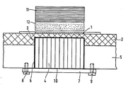
- the figure shows a section through a microwave circulator according to the invention.
- a dielectric substrate 2 which is not made of ceramic (aluminum oxide) as usual, but made of a soft material, e.g. a polytetrafluoroethylene ceramic compound, which are also known under the trade names such as RT-Duroid or DI-Clad.
- a soft material e.g. a polytetrafluoroethylene ceramic compound, which are also known under the trade names such as RT-Duroid or DI-Clad.
- Such substrate materials are much easier to machine than hard ceramic materials, which has a particularly favorable effect when machining the recess 3 in the substrate.
- the recess 3 is located below the strip line junction 1 applied to the top of the substrate 2.
- a ferrite disc 4 is inserted into the recess 3, the depth of which is less than the substrate thickness, and partially protrudes from the recess 3.
- a metal plate 5 (for example made of aluminum) serves as a carrier for the substrate 2 and as a ground line for the strip line structure 1 located on the upper side of the substrate.
- a bore 6 is provided which serves to receive the part of the ferrite disc 4 which protrudes from the substrate recess 3.
- the bore opening on the side (bottom side) of the metal plate 5 opposite the substrate 2 is covered with an electrically conductive disc 7, as a result of which the ferrite disc 4 is held in the bore 6 and the recess 3.
- the disc 7 is electrically contacted with the metal plate 5 by means of screws 8 and 9.
- An electrically conductive metal foil 10 placed between the disc 7, the metal plate 5 and the ferrite disc 4 improves the galvanic contact of the disc 7 with the metal plate 5 and serves to compensate for any difference between the thickness of the ferrite disc 4 and the depth of the recess 3 and hole 6.
- the impedance of the strip line junction 1 can be varied as a function of the ferrite disc thickness and can thus be set to a desired value.
- the stability of the thin substrate area present above the recess 3 can be improved in that the ferrite disc 4 is glued into the recess 3.
- a dielectric filler introduced into the recess 3 between the ferrite disc 4 and the substrate 2 avoids the formation of an air gap.
- the static magnetic field required for the circulator is generated by a permanent magnet 11 arranged above the stripline structure 1, which is glued to a metallic or dielectric spacer 12 in the exemplary embodiment shown.
- a permanent magnet 11 arranged above the stripline structure 1, which is glued to a metallic or dielectric spacer 12 in the exemplary embodiment shown.
- other known magnet systems can also be used.
- the microwave circulator described above can be produced with little effort because no metallization of the ferrite disc and no soldering to the substrate ground surface is required and an easily machinable substrate made of soft material is used.
- An exemplary embodiment of a circulator according to the invention with an RT-Duroid 6010 substrate of 635 ⁇ m thickness, a recess of approx. 300 ⁇ m depth embedded therein and a metal plate of approx. 3 mm thickness has a frequency bandwidth of ⁇ 20% at an operating frequency of 4 GHz. , a transmission loss of ⁇ 0.3 dB, a blocking loss of ⁇ 20 dB and an input standing wave ratio of ⁇ 1.2.
Landscapes
- Non-Reversible Transmitting Devices (AREA)
- Constitution Of High-Frequency Heating (AREA)
Priority Applications (1)
| Application Number | Priority Date | Filing Date | Title |
|---|---|---|---|
| AT86104356T ATE80500T1 (de) | 1985-04-03 | 1986-03-29 | Mikrowellen-zirkulator. |
Applications Claiming Priority (2)
| Application Number | Priority Date | Filing Date | Title |
|---|---|---|---|
| DE3512142 | 1985-04-03 | ||
| DE19853512142 DE3512142A1 (de) | 1985-04-03 | 1985-04-03 | Mikrowellen-zirkulator |
Publications (3)
| Publication Number | Publication Date |
|---|---|
| EP0197476A2 true EP0197476A2 (fr) | 1986-10-15 |
| EP0197476A3 EP0197476A3 (en) | 1988-08-31 |
| EP0197476B1 EP0197476B1 (fr) | 1992-09-09 |
Family
ID=6267183
Family Applications (1)
| Application Number | Title | Priority Date | Filing Date |
|---|---|---|---|
| EP86104356A Expired - Lifetime EP0197476B1 (fr) | 1985-04-03 | 1986-03-29 | Circulateur à micro-ondes |
Country Status (3)
| Country | Link |
|---|---|
| EP (1) | EP0197476B1 (fr) |
| AT (1) | ATE80500T1 (fr) |
| DE (2) | DE3512142A1 (fr) |
Cited By (3)
| Publication number | Priority date | Publication date | Assignee | Title |
|---|---|---|---|---|
| AU598595B2 (en) * | 1986-10-22 | 1990-06-28 | Siemens Telecomunicazioni S.P.A. | Thin-film circulator with three matched gates |
| EP0962980A1 (fr) * | 1998-06-05 | 1999-12-08 | Thomson-Csf | Module micro-électronique hyperfréquences comportant deux matériaux de substrat différents et procédé de fabrication d'un tel module |
| US11152677B2 (en) * | 2018-11-12 | 2021-10-19 | Qorvo Us, Inc. | Integration of self-biased magnetic circulators with microwave devices |
Families Citing this family (1)
| Publication number | Priority date | Publication date | Assignee | Title |
|---|---|---|---|---|
| CN103855456A (zh) * | 2012-11-29 | 2014-06-11 | 中国航空工业第六○七研究所 | 一种嵌入式微带环行器的制作方法 |
Family Cites Families (5)
| Publication number | Priority date | Publication date | Assignee | Title |
|---|---|---|---|---|
| US3334317A (en) * | 1964-01-31 | 1967-08-01 | Sylvania Electric Prod | Ferrite stripline circulator having closed magnetic loop path and centrally located, conductive foil overlying radially extending center conductors |
| US3573666A (en) * | 1969-02-27 | 1971-04-06 | Gen Electric | Frequency adjustable microwave stripline circulator |
| US3614670A (en) * | 1969-11-05 | 1971-10-19 | Richard G Wilson | Switchable microwave circulator wherein ground planes are comprised of foils having vertically conductive particles |
| US3854106A (en) * | 1974-02-19 | 1974-12-10 | Bendix Corp | Depressed-puck microstrip circulator |
| GB1512605A (en) * | 1976-08-05 | 1978-06-01 | Standard Telephones Cables Ltd | Microwave integrated printed circuits |
-
1985
- 1985-04-03 DE DE19853512142 patent/DE3512142A1/de not_active Withdrawn
-
1986
- 1986-03-29 DE DE8686104356T patent/DE3686663D1/de not_active Expired - Lifetime
- 1986-03-29 AT AT86104356T patent/ATE80500T1/de not_active IP Right Cessation
- 1986-03-29 EP EP86104356A patent/EP0197476B1/fr not_active Expired - Lifetime
Cited By (4)
| Publication number | Priority date | Publication date | Assignee | Title |
|---|---|---|---|---|
| AU598595B2 (en) * | 1986-10-22 | 1990-06-28 | Siemens Telecomunicazioni S.P.A. | Thin-film circulator with three matched gates |
| EP0962980A1 (fr) * | 1998-06-05 | 1999-12-08 | Thomson-Csf | Module micro-électronique hyperfréquences comportant deux matériaux de substrat différents et procédé de fabrication d'un tel module |
| FR2779576A1 (fr) * | 1998-06-05 | 1999-12-10 | Thomson Csf | Module micro-electronique hyperfrequences comportant deux materiaux de substrat differents et procede de fabrication d'un tel module |
| US11152677B2 (en) * | 2018-11-12 | 2021-10-19 | Qorvo Us, Inc. | Integration of self-biased magnetic circulators with microwave devices |
Also Published As
| Publication number | Publication date |
|---|---|
| DE3686663D1 (de) | 1992-10-15 |
| ATE80500T1 (de) | 1992-09-15 |
| EP0197476B1 (fr) | 1992-09-09 |
| DE3512142A1 (de) | 1986-10-09 |
| EP0197476A3 (en) | 1988-08-31 |
Similar Documents
| Publication | Publication Date | Title |
|---|---|---|
| EP0338447A2 (fr) | Arrangement pour dissiper la chaleur d'un composant sur un circuit imprimé | |
| DE1591427B1 (de) | Zirkulator und verfahren zum herstellen eines zirkulators | |
| EP0197476B1 (fr) | Circulateur à micro-ondes | |
| DE2929547C2 (de) | Mikrowellen-Dämpfungsglied | |
| DE2522918A1 (de) | Richtungsleitung mit feldverschiebungseffekt | |
| DE2743305C2 (de) | Mikrowellen-Zirkulator auf einem Substrat | |
| DE1614858C3 (de) | Halbleiteranordnung | |
| DE2908255C2 (de) | Y-Zirkulator | |
| DE2833772C2 (de) | Richtkoppler | |
| DE2253175A1 (de) | Zirkulator mit in mic-technik ausgebildeten anschlussarmen | |
| DE3207818A1 (de) | Schaltung mit einem mikrostrip | |
| DE2818854C2 (de) | Zirkulator, insbesondere für integrierte Mikrowellenschaltkreise | |
| DE2253122C3 (de) | Zirkulator, insbesondere für integrierte Mikrowellenschaltungskreise | |
| DE2253176C3 (de) | Y-Verzweigungszirkulator für die Verwendung in integrierten Mikrowellen-Schaltungskreisen | |
| DE1639458B1 (de) | Halbleiteranordnung | |
| EP0163289A2 (fr) | Dispositif réalisant une transition entre une ligne à microbande et une ligne coplanaire à deux bandes | |
| DE1791108B1 (de) | Mehrarmiger zirkulator | |
| DE2133647B2 (de) | Abschlusswiderstand fuer hoechstfrequenz-uebertragungsleitungen in band- oder streifenleitungstechnik | |
| DE4106655A1 (de) | Daempfungsglied fuer eine mikrostreifenleitungsschaltung | |
| DE1591427C (de) | Zirkulator und Verfahren zum Herste! len eines Zirkulators | |
| DE3034034A1 (de) | Y-zirkulator in streifenleitungsbauweise | |
| DE2813586C2 (de) | Abschlußwiderstand für Microstripleitungen | |
| DE1945839B2 (de) | Abschlusswiderstand in Streifenleitungstechnik | |
| DE3804205A1 (de) | Elektrischer hohlleiterschalter | |
| DE2042146A1 (de) | Y-Zirkulator in Streifenleitungsbauweise |
Legal Events
| Date | Code | Title | Description |
|---|---|---|---|
| PUAI | Public reference made under article 153(3) epc to a published international application that has entered the european phase |
Free format text: ORIGINAL CODE: 0009012 |
|
| AK | Designated contracting states |
Kind code of ref document: A2 Designated state(s): AT CH DE LI NL SE |
|
| PUAL | Search report despatched |
Free format text: ORIGINAL CODE: 0009013 |
|
| AK | Designated contracting states |
Kind code of ref document: A3 Designated state(s): AT CH DE LI NL SE |
|
| 17P | Request for examination filed |
Effective date: 19880921 |
|
| 17Q | First examination report despatched |
Effective date: 19910227 |
|
| GRAA | (expected) grant |
Free format text: ORIGINAL CODE: 0009210 |
|
| AK | Designated contracting states |
Kind code of ref document: B1 Designated state(s): AT CH DE LI NL SE |
|
| REF | Corresponds to: |
Ref document number: 80500 Country of ref document: AT Date of ref document: 19920915 Kind code of ref document: T |
|
| REF | Corresponds to: |
Ref document number: 3686663 Country of ref document: DE Date of ref document: 19921015 |
|
| PLBE | No opposition filed within time limit |
Free format text: ORIGINAL CODE: 0009261 |
|
| STAA | Information on the status of an ep patent application or granted ep patent |
Free format text: STATUS: NO OPPOSITION FILED WITHIN TIME LIMIT |
|
| 26N | No opposition filed | ||
| PGFP | Annual fee paid to national office [announced via postgrant information from national office to epo] |
Ref country code: SE Payment date: 19940325 Year of fee payment: 9 |
|
| PGFP | Annual fee paid to national office [announced via postgrant information from national office to epo] |
Ref country code: AT Payment date: 19940328 Year of fee payment: 9 |
|
| PGFP | Annual fee paid to national office [announced via postgrant information from national office to epo] |
Ref country code: NL Payment date: 19940331 Year of fee payment: 9 |
|
| PGFP | Annual fee paid to national office [announced via postgrant information from national office to epo] |
Ref country code: CH Payment date: 19940420 Year of fee payment: 9 |
|
| EAL | Se: european patent in force in sweden |
Ref document number: 86104356.0 |
|
| PG25 | Lapsed in a contracting state [announced via postgrant information from national office to epo] |
Ref country code: AT Effective date: 19950329 |
|
| PG25 | Lapsed in a contracting state [announced via postgrant information from national office to epo] |
Ref country code: SE Effective date: 19950330 |
|
| PG25 | Lapsed in a contracting state [announced via postgrant information from national office to epo] |
Ref country code: LI Effective date: 19950331 Ref country code: CH Effective date: 19950331 |
|
| PG25 | Lapsed in a contracting state [announced via postgrant information from national office to epo] |
Ref country code: NL Effective date: 19951001 |
|
| REG | Reference to a national code |
Ref country code: CH Ref legal event code: PL |
|
| NLV4 | Nl: lapsed or anulled due to non-payment of the annual fee |
Effective date: 19951001 |
|
| EUG | Se: european patent has lapsed |
Ref document number: 86104356.0 |
|
| PGFP | Annual fee paid to national office [announced via postgrant information from national office to epo] |
Ref country code: DE Payment date: 19990607 Year of fee payment: 14 |
|
| PG25 | Lapsed in a contracting state [announced via postgrant information from national office to epo] |
Ref country code: DE Free format text: LAPSE BECAUSE OF NON-PAYMENT OF DUE FEES Effective date: 20010103 |