EP0197894A2 - Einrichtung mit einer modularen elektrischen oder elektronischen Schaltung und ein Verbinder zum Anschliessen der Schaltung an ein autonomes elektrisches System - Google Patents
Einrichtung mit einer modularen elektrischen oder elektronischen Schaltung und ein Verbinder zum Anschliessen der Schaltung an ein autonomes elektrisches System Download PDFInfo
- Publication number
- EP0197894A2 EP0197894A2 EP86810156A EP86810156A EP0197894A2 EP 0197894 A2 EP0197894 A2 EP 0197894A2 EP 86810156 A EP86810156 A EP 86810156A EP 86810156 A EP86810156 A EP 86810156A EP 0197894 A2 EP0197894 A2 EP 0197894A2
- Authority
- EP
- European Patent Office
- Prior art keywords
- housing
- shoe
- tongue
- recess
- tracks
- Prior art date
- Legal status (The legal status is an assumption and is not a legal conclusion. Google has not performed a legal analysis and makes no representation as to the accuracy of the status listed.)
- Withdrawn
Links
Images


Classifications
-
- H—ELECTRICITY
- H01—ELECTRIC ELEMENTS
- H01R—ELECTRICALLY-CONDUCTIVE CONNECTIONS; STRUCTURAL ASSOCIATIONS OF A PLURALITY OF MUTUALLY-INSULATED ELECTRICAL CONNECTING ELEMENTS; COUPLING DEVICES; CURRENT COLLECTORS
- H01R12/00—Structural associations of a plurality of mutually-insulated electrical connecting elements, specially adapted for printed circuits, e.g. printed circuit boards [PCB], flat or ribbon cables, or like generally planar structures, e.g. terminal strips, terminal blocks; Coupling devices specially adapted for printed circuits, flat or ribbon cables, or like generally planar structures; Terminals specially adapted for contact with, or insertion into, printed circuits, flat or ribbon cables, or like generally planar structures
- H01R12/50—Fixed connections
- H01R12/59—Fixed connections for flexible printed circuits, flat or ribbon cables or like structures
- H01R12/592—Fixed connections for flexible printed circuits, flat or ribbon cables or like structures connections to contact elements
-
- H—ELECTRICITY
- H01—ELECTRIC ELEMENTS
- H01R—ELECTRICALLY-CONDUCTIVE CONNECTIONS; STRUCTURAL ASSOCIATIONS OF A PLURALITY OF MUTUALLY-INSULATED ELECTRICAL CONNECTING ELEMENTS; COUPLING DEVICES; CURRENT COLLECTORS
- H01R12/00—Structural associations of a plurality of mutually-insulated electrical connecting elements, specially adapted for printed circuits, e.g. printed circuit boards [PCB], flat or ribbon cables, or like generally planar structures, e.g. terminal strips, terminal blocks; Coupling devices specially adapted for printed circuits, flat or ribbon cables, or like generally planar structures; Terminals specially adapted for contact with, or insertion into, printed circuits, flat or ribbon cables, or like generally planar structures
- H01R12/70—Coupling devices
- H01R12/82—Coupling devices connected with low or zero insertion force
- H01R12/85—Coupling devices connected with low or zero insertion force contact pressure producing means, contacts activated after insertion of printed circuits or like structures
- H01R12/89—Coupling devices connected with low or zero insertion force contact pressure producing means, contacts activated after insertion of printed circuits or like structures acting manually by moving connector housing parts linearly, e.g. slider
-
- H—ELECTRICITY
- H01—ELECTRIC ELEMENTS
- H01R—ELECTRICALLY-CONDUCTIVE CONNECTIONS; STRUCTURAL ASSOCIATIONS OF A PLURALITY OF MUTUALLY-INSULATED ELECTRICAL CONNECTING ELEMENTS; COUPLING DEVICES; CURRENT COLLECTORS
- H01R29/00—Coupling parts for selective co-operation with a counterpart in different ways to establish different circuits, e.g. for voltage selection, for series-parallel selection, programmable connectors
Definitions
- the present invention aims to allow a generalization of use of this principle of "electronic cards” and proposes, for this purpose, an assembly including a modular electric or electronic circuit and a connector designed to connect this circuit to a system electric autonane, this assembly comprising, cam known similar assemblies, a housing, containing both said circuit and the connector, and its means for removably fixing the housing to the system in a position allowing said galvanic connection between a first plurality of conductive tracks , electrically attached to the points of the circuit to be connected to the system, and a second plurality of homologous conductive tracks belonging to this system.
- Such a modular assembly must, in fact, have a simple general architecture, be particularly reliable, inexpensive and of particularly reduced dimensions, in particular as regards the thickness.
- the assembly according to the invention should, in fact, be able to be associated with a pocket computer, or genre described for example in European patent application No. 0 053 061, that is to say a computer of very low size since its maximum dimensions are generally of the order of 20 cm in length x it in width, x 2.5 to 3 cm in thickness.
- a computer includes in particular a keyboard of the “transparent touch sensitive” type, occupying practically the entire surface of one of those main faces of the housing of the computer, and a liquid crystal display cell.
- the assembly in question must include in its housing a manual actuation mechanism, with a miniaturized structure, of the putting into and out of service of the modular electric or electronic circuit, which is also integrated in the case, and which must also perform, simultaneously, the locking of this assembly on the autonomous system to which it is intended to be electrically connected, in the operating position "of the circuit.
- German applicants EP 858100014.2 and EP 85900608.2 already write a modular unit meeting the above criteria: with regard to the requests which only cover Italy, France and the United Kingdom, the applicant proceeded on her own initiative to a limitation and presented two distinct sets of claims, one (A), valid for the designations of Italy, France and the United Kingdom, drawn up in application of Art. 54 (3) EPC, the other (B), valid for designations to Austria, Belgium, Luxembourg, the Netherlands, the Federal Republic of Germany, Sweden and Switzerland, countries in which the above European patent applications do not constitute prior art as regards the novelty opposable to the set of claims concerned by these countries.
- the computer shown in FIGS. 1 and 2 is a pocket computer, of a type similar to that described in European patent application No. 0 053 061, that is to say a computer with particularly reduced dimensions ( 20 x 11 x 3 cm approximately) for an exceptionally high quality of service in such a small volume.
- the upper face of such a computer has, in its central part, a rectangular screen E including a keyboard of the "transparent touch sensitive” type and a cell with liquid crystal display (LCD) arranged under the keyboard, screen which is surrounded by a belt C of keys for control and actuation of the computer.
- a rectangular screen E including a keyboard of the "transparent touch sensitive” type and a cell with liquid crystal display (LCD) arranged under the keyboard, screen which is surrounded by a belt C of keys for control and actuation of the computer.
- LCD liquid crystal display
- the illustrated computer has various adjustment buttons (Rl, R2) and control push buttons, either a push button (Pl) for switching on the computer, a second push button (P2) for starting it and a third push button (P3) to reset the computer system, sockets (Fl to F4) allowing connection to various devices (microphane, cassette player, earphone for example), an RS 232 serial output before allowing connection ae peripherals, such as a printer for example, a female PF socket for connecting the computer to an external power source, a PS passage, provided in the housing of the apparatus for a gripping strap (not shown), a parallel connector CP, has 40 pins, for the connection of the computer speaker to a moaem, to a printer or to a measuring device for example, the opening of a compartment intended to receive wires to power supply computer, opening not visible in drawing ca r masked by a cover CP slidably mounted in a groove RA hollowed out in the housing, this cover thus being capable of being driven from
- the computer represented comprises a push-button PR making it possible to control the RESET function of the computer, a loudspeaker HP and four housings Ll a L4 intended to receive a number corresponding to removable assemblies El to E4, the structural features of which will be illustrated below and forming as many "memory cards" RAM and / or ROM, capable of constituting a storage memories with information generated using the computer and / or memories containing these utility programs of all kinds.
- the computer comprises, moreover, in the volume portion of its housing included, in essence, between the screen E and the housings L1 to L4, in particular all of the logic circuits and connections necessary both for the operation of the keyboard and the display and for the management and execution of the various functions specific to the computer. All these elements not having a direct relationship with the essential characteristics of the assembly according to the invention have not been shown and will not be described.
- the above memory cards must have these reduced dimensions, of the order of 55 x 45 mm on a side and about 3 mm thick, and be able to be fixed on the computer (or separated from it) manually, without making use of particular tools, their electrical connection having to be flawless and remaining such whatever the movements and modifications may be this position that the computer can be called to know.
- the invention provides an assembly encompassing a modular electric or electronic circuit and a connector intended to allow galvanic connection of this circuit to an autonomous electrical system, even different from a computer.
- a modular electric or electronic circuit and a connector intended to allow galvanic connection of this circuit to an autonomous electrical system, even different from a computer.
- the modular assembly El is intended to be inserted into the housing Ll of the computer speaker with a view to being galvanically connected thereto by means of bars / bus e of which only about twenty of them have been shown so as not to load the figure unnecessarily.
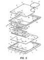
- FIG. 5 Such an assembly is obtained, in essence, by superimposing and assembling these various parts which will now be described with particular reference to Figures 3 to 7 of the accompanying drawings.
- It comprises (tig. 5) a housing formed by a rectangular base 1 on which rests a frame 2 whose opening is closed by a cover 3.
- the illustrated assembly has a plate 4, made of flexible insulating material, constituting a printed circuit, or PC board, on which are fixed the "chips" of the logic circuits specific to each set, chips which have not been shown but which take place in the volume P left free between this plate 4, the frame 2, the cover 3 and a filling mass M, of epoxy resin for example (figs 3 and 4).
- the four elements 1 to 4 are assembled by means of screws (not shown) engaging in openings 1 and 1 "of the base 1 and passing through the corresponding passages 2 'and 2", 3' and 3 ", 4 'and 4 ", arranged respectively in elements 2, 3 and 4.
- the same assembly could be produced by plugs made of hot-melt material protruding for example at the places occupied by the openings 1' of the base 1 and ocnt it would cause the fusion of the upper end at the end of the assembly to form a clamping head.
- both the base 1 and the frame 2 will preferably be made of molded plastic, for example ABS teflon doped; as regards the cover 3, it will however be obtained by stamping a sheet of stainless steel.
- the openings 1 ′′ of the base 1 are made in cylindrical bosses la and lb projecting from the bottom of the base, in close proximity to the rear edge of a window lf, these bosses forming a positioning member for the PC-board 4, by engagement in openings 4a and 4b, for a spring-comb 5, respectively for a cross-member 6, by engagement in openings 5a and 5b, respectively 6a and 6b.
- position ae these bosses is marked by the representation of their axis of symmetry AA.
- the bosses 1a and 1b constitute, in addition, positioning members and a guide in its possible rectilinear displacements, in direction ⁇ 1 or ⁇ 2, for a shoe 7 by engagement in oblong openings 7a and 7b, oriented along the axis ⁇ 1- ⁇ 2.
- the length of these openings, 7a and 7b, and the diameter of the bosses la and lb of the base 1 determine the amplitude of the axial displacement possible for the shoe 7, in the direction ⁇ 1- ⁇ 2.
- This shoe is provided with a lamellar rostrum alum 7c (figs 3 to 5), cut by three parallel slots 7d forming as many gripping means to allow a user to control, for example with the finger, the sliding of the shoe from a first limit position , ae withdrawal (fig. 3), in a second projecting limit position (fig. 4), in which the rostrum 7c engages in a receiving slot t2 that has the side wall of each housing L1 to L4 of the computer.
- a lamellar rostrum alum 7c (figs 3 to 5)
- three parallel slots 7d forming as many gripping means to allow a user to control, for example with the finger, the sliding of the shoe from a first limit position , ae withdrawal (fig. 3), in a second projecting limit position (fig. 4), in which the rostrum 7c engages in a receiving slot t2 that has the side wall of each housing L1 to L4 of the computer.
- the outer periphery of this base has a chevron profile on those adjacent sides, lc and ld, and a homologous grooved profile on its two other sides. , le and 1t. Indeed, any set El and E4 cannot be introduced into the corresponding housing, L1. to L4, from the computer that by sliding in the direction ⁇ 1, in a groove l3, for the side lc, and on a slide l4, for the side of homologous shape, provided on the longitudinal edges of each housing Ll to L4 .
- the caare 2 has a rectangular cutout 2a, of width and length corresponding practically to the width and the length of the rostrum 7c.
- the cover 3 is also provided with a rectangular cutout 3a, of magnets corresponding to those of the cutout Za of the frame 2, these two cutouts being positioned so that, in the assembled position of the elements ae the structure shown in Figs 3 to 5, they are located exactly one above the other, the edges of the cutout 2a embracing the rostrum 7c on its two longitudinal sides.
- the frame 2 is provided, on its underside , a peripheral rib 2b, which fits around the periphery of the upper opening 1g of the base 1, and, on its upper face, has a groove 2c (figs 3 and 5) intended to receive the edge curved 3b of the cover 3.
- This rib also serves to fit a shutter 3 * intended to cover a battery (not shown) taking place in the volume portion between the PC-board 4 (4c and 4a represent positive contacts and negative to which the battery is attached), the space delimited by the portion of the frame 2 of the upper right corner thereof (fig. 5) and by the shutter 3 *.
- This battery is in fact intended for supplying power to electronic "chips" carried by the PC-boara 4; it is in particular necessary when the chips are aes RAM of which one wants to keep the memorized information even once the set El to E4 corresponding distant from the computer.
- the fixing of this shutter on the cover 3 is carried out by these screws, not shown, fitting the shutter 3 * through passages 3 * ', the frame 2 and the circuit 4 and being fixed in the base 1 by aans engagement the three openings 1 'located in the drawing, in the upper right part of this base.
- the base 1 develops in the shape of a batten li, of thickness corresponding to that of the cross-member 6 and having, on its upper face, a rib li on which bears the rostrum 7c of the shoe 7. It will also be noted that the lower face of the batten li extends at a level higher than that of the fona of the base 1 of a corresponding value sum these thicknesses of the comb 5 and the printed circuit 4.
- the assembly according to the invention further comprises a bar 8, of circular section, whose diameter, greater than the thickness that the cross 6, corresponds substantially ment to the thickness of the batten linked to the level of the rib lj, and the length of which is identical, both to that of this cross, to that of the comb 5 and to that of the shoe 7 while being slightly less than the length ae of the rectangular window lh presented by the tona of the base 1.
- This bar is freely engaged in a rectangular slot 9, of width slightly greater than that of the diameter of the bar 8 and which is limited, for its longitudinal edges, by the edge of the slat li and by the anterior edge (in aessin-fig. 5) of the cross 6 and, for its transverse edges, by aes portions of the sides Id and If of the base.
- the shoe 7 is engaged, by its rear part, 7th, in a slot with rectangular section, 10, the walls of which are constituted by the frame 2, by the mass filling V and by a portion of the cross member 6 on which this shoe rests by a first flat part 7f of the sole, adjoining a second part 7g, with inclined profile, leading to the rostrum 7c of the shoe.
- the thickness of this shoe, in its part engaged in the slot 10 is slightly less than the width of this slot so that the shoe can be moved by sliding, in direction ⁇ 1, from its withdrawal position (fig 3) in its protruding position (fig.
- the bar 8 is in contact, both with the shoe 7, by a longitudinal edge, and with the comb 5, by another similar edge, situated in a position diametrically opposite to the first edge.
- this comb which is constituted, as described, by a stainless steel leaf spring, is fixed, for example by gluing, on the upper face to the portion of the PC-board 4 which is clamped between the bottom of the base 1 and the cross-member 6 as well as that which projects freely into a housing 11. (figs 3 and 4), near the bottom of the latter, logembent which is delimited you both by the base 1 (in particular by the rib li and by the bottom of this base) and by the cross-member 6.
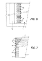
- the free end of the comb 5 is cut by a series of teeth 5c weakening this end and giving it, therefore, increased flexibility.
- the spacing and the width of these cents 5c corresponds in fact to the spacing and the width both of the busbars appearing on the bottom of each housing L1 to L4 of the computer (FIGS. 2 and 6) as of a corresponding number of conductive tracks 12 with which the underside of the PC-board 4 is furnished (fig. 7), these tracks extending up to the interior of the volume V in which the chips of the electronic card which are formed are arranged.
- 'set E considers and forms part of the coupling circuit of these chips.
- the tracks 12 are preferably coated with a contact layer with a precious metal, such as gold.
- a precious metal such as gold.
- such tracks may have a width of the order of 8 tenths ae millimeter for a spacing of the orare of 4 tenths of a millimeter. They could, if necessary, even have these dimensions at a lower value while being assured of the maintenance of their intrinsic qualities for a particularly important life.
- the general architecture of the assembly 5 described makes it possible to obtain mutual contact between two sets of tracks in presence (l and 12) with very gentle reciprocal friction and progressive in its intensity and therefore without pro- ducticn of "scratch".
- this shoe delimits, in cooperation with the rib li of the base 1 and the cross 6, a vice space Va aans which opens the slot 9.
- the height from this space Va, the diameter of the bar 8 as well as the thickness of the rib li and of the cross-member 6 are advantageously chosen such that, in the position this withdrawal of the shoe 7 (fig. 3), this bar can partially penetrate into the space goes under the action of the elastic blade forming the comb 5 so that the assembly formed by this comb and by the PC-board 4 to which it is glued then occupies a practically horizontal position, retracted inside the recess 11.
- the PC-board occupies the position visible in FIG. 4, in which its own tracks are applied practically over the entire length of the tracks l mentioned, by exerting sufficient pressure to guarantee an electrical contact started.
- the bar 8 has a cylindrical profile
- the bending under the action of this bar ae the comb 5 - PC-board 4 assembly is effected in this way particularly smoothly, smoothly, the bar being able to roll on itself, inside the slot 9, and on the surface of the comb 5, thus contributing to obtain a particularly soft contacting of the conductive tracks on the PC-board with those appearing on the bottom of the housing L.
- the assembly according to the invention can be put in place in the corresponding groove without having to exert with great efforts; during this insertion, the conductive tracks which it comprises are not liable to be torn off, these being retracted inside the housing 11 of the assembly.
Landscapes
- Coupling Device And Connection With Printed Circuit (AREA)
- Details Of Connecting Devices For Male And Female Coupling (AREA)
- Calculators And Similar Devices (AREA)
- Connector Housings Or Holding Contact Members (AREA)
Applications Claiming Priority (2)
| Application Number | Priority Date | Filing Date | Title |
|---|---|---|---|
| CH1440/85A CH665059A5 (fr) | 1985-04-03 | 1985-04-03 | Ensemble englobant un circuit modulaire electrique ou electronique et un connecteur destine a relier le circuit a un systeme electrique autonome. |
| CH1440/85 | 1985-04-03 |
Publications (2)
| Publication Number | Publication Date |
|---|---|
| EP0197894A2 true EP0197894A2 (de) | 1986-10-15 |
| EP0197894A3 EP0197894A3 (de) | 1989-05-31 |
Family
ID=4210506
Family Applications (1)
| Application Number | Title | Priority Date | Filing Date |
|---|---|---|---|
| EP86810156A Withdrawn EP0197894A3 (de) | 1985-04-03 | 1986-04-01 | Einrichtung mit einer modularen elektrischen oder elektronischen Schaltung und ein Verbinder zum Anschliessen der Schaltung an ein autonomes elektrisches System |
Country Status (4)
| Country | Link |
|---|---|
| US (1) | US4723195A (de) |
| EP (1) | EP0197894A3 (de) |
| JP (1) | JPS61292716A (de) |
| CH (1) | CH665059A5 (de) |
Cited By (2)
| Publication number | Priority date | Publication date | Assignee | Title |
|---|---|---|---|---|
| EP0402613A3 (de) * | 1989-06-15 | 1991-03-06 | International Business Machines Corporation | Verbinderanordnung mit einem beweglichen Wagen |
| EP0475717A1 (de) * | 1990-09-12 | 1992-03-18 | Yamaichi Electric Co., Ltd. | Sockel für elektrisches Bauteil |
Families Citing this family (12)
| Publication number | Priority date | Publication date | Assignee | Title |
|---|---|---|---|---|
| JP2860362B2 (ja) * | 1990-03-17 | 1999-02-24 | アムフェノル―トゥヘル、エレクトロニクス、ゲゼルシャフト、ミット、ベシュレンクテル、ハフツング | 接触装置、特に加入者識別モジュールの接触装置 |
| US5544007A (en) * | 1991-07-19 | 1996-08-06 | Kabushiiki Kaisha Toshiba | Card-shaped electronic device used with an electronic apparatus and having shield plate with conductive portion on a lateral side |
| US5452468A (en) | 1991-07-31 | 1995-09-19 | Peterson; Richard E. | Computer system with parallel processing for information organization |
| US6643656B2 (en) * | 1991-07-31 | 2003-11-04 | Richard Esty Peterson | Computerized information retrieval system |
| JP4057437B2 (ja) * | 2003-02-04 | 2008-03-05 | 株式会社東海理化電機製作所 | 携帯機 |
| JP2005039037A (ja) * | 2003-07-14 | 2005-02-10 | Tanaka Kikinzoku Kogyo Kk | 摺動子 |
| US7433185B1 (en) * | 2004-09-10 | 2008-10-07 | Micro Industries Corporation | Integrated display computer stand with integrated peripherals |
| US7698491B1 (en) * | 2007-09-26 | 2010-04-13 | Emc Corporation | Modular patch panel with pluggable personalities |
| TWI360376B (en) | 2008-04-11 | 2012-03-11 | E Ink Holdings Inc | Flexible display apparatus |
| US9839072B2 (en) * | 2012-03-08 | 2017-12-05 | Eberspacher Catem Gmbh & Co. Kg | Heat generating element with connection structure |
| GB2523121A (en) * | 2014-02-12 | 2015-08-19 | Koh Technology Ltd | Modular Computer |
| DE202017100172U1 (de) * | 2017-01-13 | 2018-04-16 | Weidmüller Interface GmbH & Co. KG | Elektronikmodul und Montagebasis mit einem Elektronikmodul |
Family Cites Families (17)
| Publication number | Priority date | Publication date | Assignee | Title |
|---|---|---|---|---|
| GB887101A (en) * | 1958-05-01 | 1962-01-17 | Ass Elect Ind | Improvements relating to mounting arrangements for electrical components |
| US3065446A (en) * | 1958-09-29 | 1962-11-20 | Cannon Electric Co | Electrical connector for strip cable |
| US3082398A (en) * | 1960-05-24 | 1963-03-19 | Amphenol Borg Electronics Corp | Electrical connectors |
| US3430186A (en) * | 1967-09-07 | 1969-02-25 | Thomas & Betts Corp | Connector assembly |
| US3491328A (en) * | 1968-08-21 | 1970-01-20 | Amp Inc | Connection device for connecting stacked tab members |
| GB1295138A (de) * | 1970-05-30 | 1972-11-01 | ||
| US3849610A (en) * | 1973-07-19 | 1974-11-19 | Amp Inc | Slide switch with individual slide operators |
| US4080027A (en) * | 1976-07-30 | 1978-03-21 | Gte Sylvania Incorporated | Electrical contact and connector |
| US4259668A (en) * | 1978-05-15 | 1981-03-31 | Sharp Kabushiki Kaisha | Television set/calculator interface including exchangeable keyboard panel and program memory cartridge |
| US4172626A (en) * | 1978-06-22 | 1979-10-30 | Amp Incorporated | Connector clip for connecting cable conductors to circuit board conductors |
| US4181386A (en) * | 1978-06-22 | 1980-01-01 | Amp Incorporated | Zero insertion force connector clip |
| US4252389A (en) * | 1979-03-27 | 1981-02-24 | Amp Incorporated | Zero insertion force connector having integral unloading means |
| CA1122285A (en) * | 1978-06-22 | 1982-04-20 | Billy E. Olsson | Electrical connector |
| US4331372A (en) * | 1980-04-24 | 1982-05-25 | Amp Incorporated | Substrate connector system utilizing a contact actuating bar |
| FR2494465B1 (fr) * | 1980-11-14 | 1987-02-13 | Epd Engineering Projectdevelop | Ordinateur de poche |
| FR2543746B1 (fr) * | 1983-03-28 | 1985-12-27 | Commissariat Energie Atomique | Microconnecteur a haute densite de contacts |
| CH655203A5 (fr) * | 1984-01-19 | 1986-03-27 | Battelle Memorial Institute | Connecteur electrique d'un module a circuit electronique. |
-
1985
- 1985-04-03 CH CH1440/85A patent/CH665059A5/fr not_active IP Right Cessation
-
1986
- 1986-04-01 JP JP61072600A patent/JPS61292716A/ja active Pending
- 1986-04-01 EP EP86810156A patent/EP0197894A3/de not_active Withdrawn
- 1986-04-02 US US06/847,256 patent/US4723195A/en not_active Expired - Fee Related
Cited By (2)
| Publication number | Priority date | Publication date | Assignee | Title |
|---|---|---|---|---|
| EP0402613A3 (de) * | 1989-06-15 | 1991-03-06 | International Business Machines Corporation | Verbinderanordnung mit einem beweglichen Wagen |
| EP0475717A1 (de) * | 1990-09-12 | 1992-03-18 | Yamaichi Electric Co., Ltd. | Sockel für elektrisches Bauteil |
Also Published As
| Publication number | Publication date |
|---|---|
| US4723195A (en) | 1988-02-02 |
| CH665059A5 (fr) | 1988-04-15 |
| EP0197894A3 (de) | 1989-05-31 |
| JPS61292716A (ja) | 1986-12-23 |
Similar Documents
| Publication | Publication Date | Title |
|---|---|---|
| EP0197894A2 (de) | Einrichtung mit einer modularen elektrischen oder elektronischen Schaltung und ein Verbinder zum Anschliessen der Schaltung an ein autonomes elektrisches System | |
| CA1147413A (fr) | Connecteur pour objets portatifs | |
| EP0696010B1 (de) | Tragbare Schnittstelle für elektronische Chipkarte | |
| EP0674287A1 (de) | Gehäuse für Chipkartenleser | |
| FR2736794A1 (fr) | Dispositif electronique portable et procede pour coupler une alimentation en courant electrique a celui-ci | |
| FR2846589A1 (fr) | Outil de poche et agencement d'une coulisse de commutation pour cet outil. | |
| FR2550014A1 (fr) | Monture de pile electrique, pour piles plates | |
| FR2685554A1 (fr) | Element modulaire de connexion electrique. | |
| EP0801445A1 (de) | Abgeschirmte Steckdose bestehend aus Kontaktstiften und Halterung für die Montage an Halteplatten | |
| EP3608885B1 (de) | Dockingstation für elektronisches zahlungsterminal, entsprechendes elektronisches zahlungsterminal und -system | |
| EP3605749B9 (de) | Halterung für ein elektrisches gerät und entsprechendes elektrisches gerät | |
| EP0801447A1 (de) | Abgeschirmter Verbinder mit Stecker und Ablagefläche ausgerüstet mit einer Ver- bzw. Entriegelungseinrichtung | |
| EP0675456B1 (de) | Gehäuse für Chipkartenleser | |
| EP1168467A1 (de) | Stromversorgungsvorrichtung für unterschiedliche Stromversorgungstypen eines tragbaren Gerätes | |
| EP0287417A1 (de) | Einrichtung zum Lesen/Schreiben elektronischer Speicherkarten, geschützt gegen Zerstörungswut | |
| FR2654556A1 (fr) | Dispositif de connexion pour un appareil utilisable avec un objet portatif, notamment une clef, a circuit integre. | |
| FR2591844A1 (fr) | Dispositif a pile pour appareil electronique equipe d'une memoire de donnees | |
| FR2649805A1 (fr) | Structure de logement pour petit objet | |
| EP0801446A1 (de) | Abgeschirmter Verbinder, insbesondere mit Stecker und Ablagefläche zum Verbinden auf einer ebenen Unterlage | |
| EP4280386B1 (de) | Elektrisches gerät mit durch das einsetzen des elektrischen leiters betätigtem automatischer anschlussklemme | |
| EP0277873B1 (de) | Selbstverriegelungssteckverbindung für Karten mit Randkontaktflächen | |
| EP1374342A1 (de) | Oberfläschenmontierungsverbinder für gedrückte schaltung und herstellungsverfahren | |
| EP2989651A1 (de) | Elektrischer schalter mit monostabiler bedientaste | |
| FR2521788A1 (fr) | Connecteur pour cartes a circuits imprimes | |
| EP1317022B1 (de) | Elektrische Buchse mit unabhängigen beweglichen Deckelteilen, speziell für elektrische Rasierer |
Legal Events
| Date | Code | Title | Description |
|---|---|---|---|
| PUAI | Public reference made under article 153(3) epc to a published international application that has entered the european phase |
Free format text: ORIGINAL CODE: 0009012 |
|
| AK | Designated contracting states |
Kind code of ref document: A2 Designated state(s): AT BE CH DE FR GB IT LI LU NL SE |
|
| PUAL | Search report despatched |
Free format text: ORIGINAL CODE: 0009013 |
|
| STAA | Information on the status of an ep patent application or granted ep patent |
Free format text: STATUS: THE APPLICATION HAS BEEN WITHDRAWN |
|
| AK | Designated contracting states |
Kind code of ref document: A3 Designated state(s): AT BE CH DE FR GB IT LI LU NL SE |
|
| 18W | Application withdrawn |
Withdrawal date: 19890501 |
|
| RIN1 | Information on inventor provided before grant (corrected) |
Inventor name: GRIMAUD, JEAN-JACQUES Inventor name: MIZZI, FRANCOIS |