EP1168467A1 - Stromversorgungsvorrichtung für unterschiedliche Stromversorgungstypen eines tragbaren Gerätes - Google Patents
Stromversorgungsvorrichtung für unterschiedliche Stromversorgungstypen eines tragbaren Gerätes Download PDFInfo
- Publication number
- EP1168467A1 EP1168467A1 EP01202255A EP01202255A EP1168467A1 EP 1168467 A1 EP1168467 A1 EP 1168467A1 EP 01202255 A EP01202255 A EP 01202255A EP 01202255 A EP01202255 A EP 01202255A EP 1168467 A1 EP1168467 A1 EP 1168467A1
- Authority
- EP
- European Patent Office
- Prior art keywords
- contact
- contact pads
- battery
- batteries
- contact pad
- Prior art date
- Legal status (The legal status is an assumption and is not a legal conclusion. Google has not performed a legal analysis and makes no representation as to the accuracy of the status listed.)
- Granted
Links
Images


Classifications
-
- H—ELECTRICITY
- H01—ELECTRIC ELEMENTS
- H01M—PROCESSES OR MEANS, e.g. BATTERIES, FOR THE DIRECT CONVERSION OF CHEMICAL ENERGY INTO ELECTRICAL ENERGY
- H01M50/00—Constructional details or processes of manufacture of the non-active parts of electrochemical cells other than fuel cells, e.g. hybrid cells
- H01M50/20—Mountings; Secondary casings or frames; Racks, modules or packs; Suspension devices; Shock absorbers; Transport or carrying devices; Holders
- H01M50/204—Racks, modules or packs for multiple batteries or multiple cells
- H01M50/207—Racks, modules or packs for multiple batteries or multiple cells characterised by their shape
- H01M50/213—Racks, modules or packs for multiple batteries or multiple cells characterised by their shape adapted for cells having curved cross-section, e.g. round or elliptic
-
- H—ELECTRICITY
- H02—GENERATION; CONVERSION OR DISTRIBUTION OF ELECTRIC POWER
- H02J—ELECTRIC POWER NETWORKS; CIRCUIT ARRANGEMENTS OR SYSTEMS FOR SUPPLYING OR DISTRIBUTING ELECTRIC POWER; SYSTEMS FOR STORING ELECTRIC ENERGY
- H02J7/00—Circuit arrangements for charging or discharging batteries or for supplying loads from batteries
- H02J7/70—Circuit arrangements for charging or discharging batteries or for supplying loads from batteries characterised by the mechanical construction
- H02J7/751—Circuit arrangements for charging or discharging batteries or for supplying loads from batteries characterised by the mechanical construction concerning the insertion or the connection of the batteries
-
- H—ELECTRICITY
- H01—ELECTRIC ELEMENTS
- H01M—PROCESSES OR MEANS, e.g. BATTERIES, FOR THE DIRECT CONVERSION OF CHEMICAL ENERGY INTO ELECTRICAL ENERGY
- H01M16/00—Structural combinations of different types of electrochemical generators
-
- H—ELECTRICITY
- H01—ELECTRIC ELEMENTS
- H01R—ELECTRICALLY-CONDUCTIVE CONNECTIONS; STRUCTURAL ASSOCIATIONS OF A PLURALITY OF MUTUALLY-INSULATED ELECTRICAL CONNECTING ELEMENTS; COUPLING DEVICES; CURRENT COLLECTORS
- H01R13/00—Details of coupling devices of the kinds covered by groups H01R12/70 or H01R24/00 - H01R33/00
- H01R13/02—Contact members
- H01R13/22—Contacts for co-operating by abutting
- H01R13/24—Contacts for co-operating by abutting resilient; resiliently-mounted
-
- Y—GENERAL TAGGING OF NEW TECHNOLOGICAL DEVELOPMENTS; GENERAL TAGGING OF CROSS-SECTIONAL TECHNOLOGIES SPANNING OVER SEVERAL SECTIONS OF THE IPC; TECHNICAL SUBJECTS COVERED BY FORMER USPC CROSS-REFERENCE ART COLLECTIONS [XRACs] AND DIGESTS
- Y02—TECHNOLOGIES OR APPLICATIONS FOR MITIGATION OR ADAPTATION AGAINST CLIMATE CHANGE
- Y02E—REDUCTION OF GREENHOUSE GAS [GHG] EMISSIONS, RELATED TO ENERGY GENERATION, TRANSMISSION OR DISTRIBUTION
- Y02E60/00—Enabling technologies; Technologies with a potential or indirect contribution to GHG emissions mitigation
- Y02E60/10—Energy storage using batteries
Definitions
- the invention relates to the field of portable devices operating with electrical energy. We are thinking in particular of mobile phones, but also of all the remote control systems for devices that can be controlled remotely, for example, by a person wearing a corresponding remote control device.
- Such a type of power supply device or “block” is described in European patent application EP-0 858 172.
- the power supply mainly comprises a cavity in which the two types of batteries can be placed.
- a first connector is intended to cooperate with a second connector incorporated in the rechargeable battery.
- a removable adapter piece is necessary to ensure the connection between the first collector and the primary batteries when these are used and placed in the cavity. This necessitates, of course, the correct positioning of this removable part, which involves the manipulation of the latter and, consequently, risks of losing it or damaging it.
- a first essential object of the invention is to remedy this drawback by proposing a supply device for a portable device capable of receiving the two types of batteries without requiring the use or manipulation by the user of a part. removable adapter.
- the main object of the invention is a device for supplying a portable device capable of using different types of supply and comprising a device box in which there is a main cavity which can accommodate two types of batteries, that is to say either at least one primary battery of a determined length, or a rechargeable battery, and in which there are two series of contact pads to allow contacting the primary batteries or the battery rechargeable with the operating circuits of the portable device, without additional removable adaptive element.
- a main embodiment of most of the studs provides that these have a swan neck shape, thus allowing great flexibility without exceeding the elastic limit of the material used.
- first keying means for mounting the primary batteries, in the sense that a battery contact pad is placed at the bottom of a notch deeper than the contact pad itself, the width of the contact pad being less than the width of the notch, itself less than the width of the stack, to allow the contact pad located on a first end of the stack to come into contact with the contact pad placed in the groove, but to prevent inserting the battery by its other end.
- second polarization means are also used for mounting the primary batteries consisting of a large, rigid contact pad, placed between two first polarization means and the nonconductive central part of which consists of a stopper placed at a distance from the edges of the notch of the corresponding battery contact pad smaller than the determined length of the batteries.
- the contact pad does not have a swan neck shape.
- NTC coefficient of negative temperature
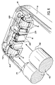
- FIG. 1 it is easy to realize the type of equipment to which the invention relates.
- a cover 1 can be seen which has to be fixed on an appliance housing 2, by means of two pins 5, after having been installed, in a cavity 3 of the appliance housing 2, either a clearance of three primary batteries 10, ie a rechargeable battery 20.
- the exploded view makes it possible to distinguish the main elements of the mobile device of the device according to the invention and the batteries or battery used.
- each of the studs is represented by one of FIGS. 2 to 5.
- FIG. 2 represents a first type of contact pad, called a battery, namely the contact pads marked 21 and 22 in FIG. 1.
- a battery namely the contact pads marked 21 and 22 in FIG. 1.
- One of them is intended to identify the type of rechargeable battery placed in the cavity 3, by means of an identification circuit of the electrical resistance of said rechargeable battery, located in the printed circuit. It is thus possible to recognize different types of rechargeable batteries, in particular those equipped with an “NTC” component meeting American standards.
- the other serves as a connection between the charging pad of the rechargeable battery and the charging circuit located on the printed circuit, which is itself connected to the charger, when the latter is connected.
- these battery contact pads are placed in electrical connection with the printed circuit board of the device comprising an electrical resistance identification circuit.
- FIG. 2 makes it possible to better distinguish the shape of the battery contact pads 21 or 22, and in particular the shape of the contact blade 23, which is straight, slightly inclined relative to a central part 24 and the end of which is slightly curved.
- the fixing of these battery contact pads 21, 22 is done by means of a lower tab 25 whose curved end makes it possible to hang a wall of the set of notches, referenced 4 in FIG. 1.
- the positioning these two battery contact pads 21 and 22 are made exactly by two lateral parts 26 which come to marry a boss 27 of the set of notches 4. Thus, these battery contact pads 21 and 22 can be fixed and detached easily from their location.
- a second type of contact pads known as mixed contact pads, referenced 31 and 32 in FIG. 1, are described. They are positioned on the device housing 2, each at one end of a of the two contact series 6 and 7, opposite and next to a battery contact pad 21 or 22.
- Figure 3 shows that their contact blade 33 is curved and ends in a swan neck towards the part which connects it to a central part 34 of this mixed contact pad. It is noted that this contact blade 33 has a width which becomes thinner as one approaches the end 37, but that the latter is wider.
- the position of such mixed studs is done by means of two curved side parts 36 to match a boss placed at one end of each of the sets of notches 4 and diametrically opposite.
- These two mixed contact pads 31 and 32 are therefore intended to establish contact between the circuits of the mobile device and both the primary batteries and a rechargeable battery, but they also constitute the positive and negative poles of the device.
- These first two types of contact pads are therefore used to power the device electrically, when a rechargeable battery is used.
- the electrical contacts for a set of primary batteries are the mixed contact pads, already described with reference to FIG. 3 and referenced 31 and 32 in FIG. 1, but also the double contact pads for batteries, 11, 12 and 13, 14 of figure 1.
- FIG. 4 represents a first of these two types of double contact pads.
- the first contact 11 of these double contact pads is intended to be inserted into a slot in the set of notches 4 of the series of foot contacts 6 (FIG. 1). It mainly comprises a bottom 46 limited by two prominent edges 48. As shown in FIG. 6, the edges at the tops of these two flanges 48 must serve as contact at the planar end 72 of a stack 10, which must be inserted between two other identical stacks 10.
- This first contact part 11 of the movable contact pad is attached to a central part 44 to which is also fixed a second contact part 12.
- Its blade 43 is of the type described in FIG. 3, referenced 33, and affects a swan neck shape. Its functions are exactly the same as those of the blade 33 of the mixed contact pad 31 or 32.
- FIG. 6 shows that such an end 47 of a blade 43 is supported in a small cavity of a set of notches 4, between the flanges 9.
- the blades 33 and 43 of the contact pads 12 and 31 are maintained in the prestressed state, in a determined position set back relative to the depth of the notch in which each is located, to avoid contact with the end. flat of a primary pile and thus participate in the polarization. Finally, this prestressing is necessary, because without it, it is difficult to ensure that the blades 43 and 33 will be set back relative to the edges 9, because the heat treatments inflicted on these blades (quenching 810 ° C and tempering 300 ° C) distort them enormously.
- the end 37 of the mixed contact pad is not blocked in the device housing 2 and is therefore not operational. Its existence allows to obtain the uniqueness of the type of mixed contact pad to lower the production cost by using a single cutting and folding tool.
- FIG. 5 shows the second type of double contact pad.
- the double contact pads of FIGS. 4 and 5 are not in contact with the printed circuit and are used only for the primary batteries. Indeed, they are used to make the connection between the primary batteries placed on the sides of the case and the primary battery being in the middle, but also for the coding of the assembly of these primary batteries.
- each of the contact pads has a tongue 29, 39, 49, 59 obtained by partial depression of the metal constituting these contact pads.
- the opening of the tongue 29, 39, 49, 59 is made upwards, so that each of them constitutes a system for blocking the contact pad in its position, and that it is difficult to remove the latter. from its location, without acting directly on each of these tabs 29, 39, 49 or 59.
- FIG. 6 provides a better understanding of how these different contact pads are installed and fixed in the housing of the device 2, and more exactly in a set of notches 4.
- the primary batteries 10 to be accepted by this case are manufactured by different companies from different countries and, therefore, their length may vary slightly.
- the contact blades and pads that accommodate them must therefore be flexible enough to accept a small difference in length, while ensuring electrical contact and keeping the batteries in place.
- the contact pad 12 has its blade 43 in the form of a swan neck placed between two flanges 9 of the set of notches 4, and does not exceed the cavity defined by these two flanges 9.
- the spacing of these two edges 9 of the set of notches 4 is greater than a contact pad 71 of the stack 10, but less than the diameter of this same stack 10.
- the keying system is as follows. If this stack is placed in the opposite direction, there will be no contact between its planar end 72 and the blade 33 of the contact pad, since it will touch before the flange 9. This is why the blade 33 of the pad contact in question is prestressed and is therefore set back from the flanges 9.
- a stop 8 molded in the set of notches 4 constitutes second polarizing means and also allows the operator not to be able to introduce the battery 10 therein by its round contact pad, but by its planar end without pad 72. This constitutes the second polarization means.
- FIG. 1 shows, on the rechargeable battery 20, the existence of contact plates 60, as well as positioning slots 61 placed in correspondence, the mixed contact pads 31 and 32 are in correspondence with these slots, when the rechargeable battery is installed. It is impossible for the user to carry out an assembly which does not correspond to that required by the operation of the device.
- the contact plates 60 make it possible to establish the electrical contact. between the battery contact pads 21 and 22, but also with the mixed contact pads 31 and 32, positive and negative.
- the rechargeable battery is designed to exact dimensions defined by the cavity 3 of the device housing 2 and the position of the two sets of notches 4. It uses soldered contacts to connect the various elements of secondary batteries constituting them. In addition, in order to protect rechargeable batteries, each of them has a thermal switch (thermo-switch), just like the component with negative temperature coefficient NTC. This avoids overloading problems during loading operations.
- thermal switch thermo-switch
- a diode is also used placed between the mixed contact pad 31, positive, for the primary batteries and the positive pole of the portable device. It should be noted that the same positive mixed contact pad 31 is used both for the batteries and for the rechargeable batteries. In correspondence, the mixed contact pad 32, diametrically opposite to the mixed contact pad 31 is the only contact pad used for grounding.
- a high elasticity can be obtained by subjecting the blades 23, 33, 43, 53 to different contact pads, a heat treatment, such as quenching at 810 ° C. and tempering at 300 ° C. for the coated XC 75 steel.
- a heat treatment such as quenching at 810 ° C. and tempering at 300 ° C. for the coated XC 75 steel.
- copper or nickel A recovery of copper makes it possible to obtain a very good bond with nickel and a coating of nickel makes it possible to obtain a very good resistance of contact between the metal and the primary cells and the rechargeable batteries whose ends are also made of nickel.
- the power supply device avoids the use of a removable part while allowing the use of both rechargeable batteries and primary batteries.
- the polarizing means prevent the user from incorrectly mounting the primary batteries.
Landscapes
- Engineering & Computer Science (AREA)
- Power Engineering (AREA)
- Chemical & Material Sciences (AREA)
- Chemical Kinetics & Catalysis (AREA)
- Electrochemistry (AREA)
- General Chemical & Material Sciences (AREA)
- Battery Mounting, Suspending (AREA)
- Charge And Discharge Circuits For Batteries Or The Like (AREA)
Applications Claiming Priority (2)
| Application Number | Priority Date | Filing Date | Title |
|---|---|---|---|
| FR0007863 | 2000-06-20 | ||
| FR0007863 | 2000-06-20 |
Publications (2)
| Publication Number | Publication Date |
|---|---|
| EP1168467A1 true EP1168467A1 (de) | 2002-01-02 |
| EP1168467B1 EP1168467B1 (de) | 2011-10-12 |
Family
ID=8851448
Family Applications (1)
| Application Number | Title | Priority Date | Filing Date |
|---|---|---|---|
| EP01202255A Expired - Lifetime EP1168467B1 (de) | 2000-06-20 | 2001-06-12 | Stromversorgungsvorrichtung für unterschiedliche Stromversorgungstypen eines tragbaren Gerätes |
Country Status (5)
| Country | Link |
|---|---|
| US (1) | US6600291B2 (de) |
| EP (1) | EP1168467B1 (de) |
| JP (1) | JP2002050331A (de) |
| KR (1) | KR100807412B1 (de) |
| CN (1) | CN1208853C (de) |
Cited By (2)
| Publication number | Priority date | Publication date | Assignee | Title |
|---|---|---|---|---|
| EP1347531A3 (de) * | 2002-03-20 | 2004-08-25 | Nec Tokin Corporation | Batteriesatz |
| CN103668919A (zh) * | 2013-11-28 | 2014-03-26 | 谢虹 | 一种迷你电熨斗 |
Families Citing this family (16)
| Publication number | Priority date | Publication date | Assignee | Title |
|---|---|---|---|---|
| FR2858123B1 (fr) * | 2003-07-23 | 2006-02-10 | Euro Prot Surveillance | Borne de connexion formant detrompeur |
| JP4595655B2 (ja) * | 2005-04-28 | 2010-12-08 | 株式会社デンソー | 電子回路装置およびその製造方法 |
| CN101079508B (zh) * | 2006-05-26 | 2010-05-12 | 朱治民 | 充电器 |
| CN101267614B (zh) * | 2007-03-16 | 2011-02-02 | 夏新科技有限公司 | 一种手机供电方法及系统 |
| CN101715609B (zh) * | 2007-06-26 | 2013-01-09 | 科尔曼公司 | 使用多种电源的电器 |
| US7897276B2 (en) | 2007-07-30 | 2011-03-01 | Hewlett-Packard Development Company, L.P. | Intersecting battery cavities |
| US8298696B1 (en) | 2008-06-03 | 2012-10-30 | Eddie Dana | Battery systems and methods thereof |
| JP5496489B2 (ja) * | 2008-11-06 | 2014-05-21 | 三洋電機株式会社 | 2種の角形パック電池の充電器 |
| US8259221B1 (en) * | 2009-04-15 | 2012-09-04 | Cisco Technology, Inc. | System and method for charging rechargeable batteries in a digital camera |
| US9912175B2 (en) * | 2010-04-23 | 2018-03-06 | 9609385 Canada Inc. | Battery harvester |
| EP2668682B1 (de) * | 2011-01-25 | 2018-05-16 | Koninklijke Philips N.V. | Batterieadapter mit flexibler schaltung und silikonfeder |
| FR2975750A1 (fr) * | 2011-05-26 | 2012-11-30 | Zedel | Dispositif d'alimentation electrique d'une lampe portative |
| US9450431B2 (en) | 2012-12-24 | 2016-09-20 | Leapfrog Enterprises, Inc. | Rechargeable battery |
| US20160372723A1 (en) * | 2015-05-19 | 2016-12-22 | MOHOC, Inc. | Battery bays and systems configured for different battery types |
| JP6888045B2 (ja) * | 2019-04-22 | 2021-06-16 | 本田技研工業株式会社 | バッテリパック |
| WO2020250087A1 (en) * | 2019-06-10 | 2020-12-17 | 3M Innovative Properties Company | Adapter for battery compartment |
Citations (6)
| Publication number | Priority date | Publication date | Assignee | Title |
|---|---|---|---|---|
| US3856577A (en) * | 1971-07-22 | 1974-12-24 | Suwa Seikosha Kk | Electrochemical cell support and contact structure |
| US5015546A (en) * | 1989-06-12 | 1991-05-14 | Grid Systems Corporation | Battery compartment |
| EP0493253A1 (de) * | 1990-12-27 | 1992-07-01 | Lg Electronics Inc. | Steckvorrichtung für Batterien |
| US5661392A (en) * | 1995-09-26 | 1997-08-26 | General Research Of Electronics, Inc. | Device for causing electronic apparatus to use a selectively mounted non-rechargeable battery pack or rechargeable battery pack |
| WO1997045900A1 (en) * | 1996-05-31 | 1997-12-04 | The Whitaker Corporation | Rechargeable battery connector |
| US6014009A (en) * | 1997-04-25 | 2000-01-11 | Data General Corporation | Electronic device |
Family Cites Families (8)
| Publication number | Priority date | Publication date | Assignee | Title |
|---|---|---|---|---|
| JPS6356560U (de) * | 1986-09-30 | 1988-04-15 | ||
| JPH1050283A (ja) * | 1996-07-31 | 1998-02-20 | Nec Shizuoka Ltd | 電池収納部の電池端子受容部 |
| FR2759523B1 (fr) | 1997-02-10 | 1999-03-19 | Alsthom Cge Alcatel | Bloc d'alimentation d'un dispositif portatif, du type permettant l'utilisation de differents types d'alimentation, et dispositif portatif correspondant |
| JPH11176404A (ja) * | 1997-12-08 | 1999-07-02 | Sony Corp | 二次電池及び電池収納装置 |
| KR100415989B1 (ko) * | 1998-07-11 | 2004-05-20 | 삼성전자주식회사 | 컴퓨터고유배터리팩또는일반배터리를사용할수있는휴대형컴퓨터 |
| US6172480B1 (en) * | 1998-10-23 | 2001-01-09 | Primetech Electronics, Inc. | Compact fast battery charger |
| JP2000149896A (ja) * | 1998-11-06 | 2000-05-30 | Nec Mobile Commun Ltd | 異種乾電池収納ケース |
| CN1685584A (zh) * | 2002-07-31 | 2005-10-19 | 瑞约伐克股份有限公司 | 检测再充电电池存在的方法与装置 |
-
2001
- 2001-06-12 EP EP01202255A patent/EP1168467B1/de not_active Expired - Lifetime
- 2001-06-16 CN CNB011254351A patent/CN1208853C/zh not_active Expired - Fee Related
- 2001-06-18 KR KR1020010034247A patent/KR100807412B1/ko not_active Expired - Fee Related
- 2001-06-18 JP JP2001183625A patent/JP2002050331A/ja active Pending
- 2001-06-20 US US09/885,706 patent/US6600291B2/en not_active Expired - Lifetime
Patent Citations (6)
| Publication number | Priority date | Publication date | Assignee | Title |
|---|---|---|---|---|
| US3856577A (en) * | 1971-07-22 | 1974-12-24 | Suwa Seikosha Kk | Electrochemical cell support and contact structure |
| US5015546A (en) * | 1989-06-12 | 1991-05-14 | Grid Systems Corporation | Battery compartment |
| EP0493253A1 (de) * | 1990-12-27 | 1992-07-01 | Lg Electronics Inc. | Steckvorrichtung für Batterien |
| US5661392A (en) * | 1995-09-26 | 1997-08-26 | General Research Of Electronics, Inc. | Device for causing electronic apparatus to use a selectively mounted non-rechargeable battery pack or rechargeable battery pack |
| WO1997045900A1 (en) * | 1996-05-31 | 1997-12-04 | The Whitaker Corporation | Rechargeable battery connector |
| US6014009A (en) * | 1997-04-25 | 2000-01-11 | Data General Corporation | Electronic device |
Cited By (3)
| Publication number | Priority date | Publication date | Assignee | Title |
|---|---|---|---|---|
| EP1347531A3 (de) * | 2002-03-20 | 2004-08-25 | Nec Tokin Corporation | Batteriesatz |
| US7183014B2 (en) | 2002-03-20 | 2007-02-27 | Nec Tokin Corporation | Battery pack |
| CN103668919A (zh) * | 2013-11-28 | 2014-03-26 | 谢虹 | 一种迷你电熨斗 |
Also Published As
| Publication number | Publication date |
|---|---|
| EP1168467B1 (de) | 2011-10-12 |
| CN1208853C (zh) | 2005-06-29 |
| KR20020000111A (ko) | 2002-01-04 |
| US6600291B2 (en) | 2003-07-29 |
| US20020060550A1 (en) | 2002-05-23 |
| KR100807412B1 (ko) | 2008-02-25 |
| CN1333572A (zh) | 2002-01-30 |
| JP2002050331A (ja) | 2002-02-15 |
Similar Documents
| Publication | Publication Date | Title |
|---|---|---|
| EP1168467B1 (de) | Stromversorgungsvorrichtung für unterschiedliche Stromversorgungstypen eines tragbaren Gerätes | |
| JP5044055B2 (ja) | パワーパック充電システムおよび電動工具充電システム | |
| EP0674287A1 (de) | Gehäuse für Chipkartenleser | |
| FR2550014A1 (fr) | Monture de pile electrique, pour piles plates | |
| CA2948387C (fr) | Dispositif cutane, notamment generateur d'impulsions pour l'electrostimulation | |
| WO2007071878A2 (fr) | Etui pour recharger un appareil electronique en situation de mobilite | |
| FR2661296A3 (fr) | Radiotelephone portable alimente par batterie. | |
| EP0675456B1 (de) | Gehäuse für Chipkartenleser | |
| FR3010581A1 (fr) | Dispositif adaptateur pour prises electriques et ensemble de prises electriques comprenant un tel dispositif | |
| FR2806863A1 (fr) | Appareil electrique portatif contenant une batterie d'accumulateurs | |
| EP2710445B1 (de) | Schutzhülle für eine spielkonsole | |
| EP0858172B1 (de) | Tragbares Gerät, und Batteriegehäuse des tragbaren Gerätes für Gebrauch von verschiedenen Batterietypen konstruiert | |
| EP1978608A1 (de) | Elektrisches Ladegerät bestehend aus mehreren Einzelteilen | |
| FR2884354A3 (fr) | Structure de logement pour batterie d'ordinateur portable | |
| FR2835681A3 (fr) | Ensemble de batteries de secours pour des appareils electroniques portables | |
| FR2806836A1 (fr) | Adaptateur de batterie | |
| WO2010125259A1 (fr) | Dispositif pour la recharge d'un appareil electronique portable | |
| FR2988068A1 (fr) | Systeme automatique de stockage de cycles, cycle pour un tel systeme et utilisation d'une batterie pour un tel cycle. | |
| EP1834366B1 (de) | Batteriebetriebene einrichtung für einen stromzähler und stromzähler | |
| FR2578103A1 (fr) | Boite a piles, notamment a usage militaire | |
| FR3132225A1 (fr) | Bouchon électronique rechargeable et socle de chargement | |
| EP1825278B1 (de) | Elektrische verbindungseinrichtung für einen polyphasen-stromzähler | |
| WO2024184301A1 (fr) | Appareil électronique portable, notamment une montre électronique, à pistes de chargement circulaires et chargeur associé | |
| FR3023150A1 (fr) | Dispositif range-accessoire pour adaptateur secteur et cordon electrique avec au moins un connecteur | |
| FR3143221A1 (fr) | Interfaces pour équipements électroniques |
Legal Events
| Date | Code | Title | Description |
|---|---|---|---|
| PUAI | Public reference made under article 153(3) epc to a published international application that has entered the european phase |
Free format text: ORIGINAL CODE: 0009012 |
|
| AK | Designated contracting states |
Kind code of ref document: A1 Designated state(s): DE FR GB Kind code of ref document: A1 Designated state(s): AT BE CH CY DE DK ES FI FR GB GR IE IT LI LU MC NL PT SE TR |
|
| AX | Request for extension of the european patent |
Free format text: AL;LT;LV;MK;RO;SI |
|
| 17P | Request for examination filed |
Effective date: 20020702 |
|
| AKX | Designation fees paid |
Free format text: DE FR GB |
|
| RAP1 | Party data changed (applicant data changed or rights of an application transferred) |
Owner name: NXP B.V. |
|
| 17Q | First examination report despatched |
Effective date: 20091214 |
|
| GRAP | Despatch of communication of intention to grant a patent |
Free format text: ORIGINAL CODE: EPIDOSNIGR1 |
|
| GRAS | Grant fee paid |
Free format text: ORIGINAL CODE: EPIDOSNIGR3 |
|
| GRAA | (expected) grant |
Free format text: ORIGINAL CODE: 0009210 |
|
| AK | Designated contracting states |
Kind code of ref document: B1 Designated state(s): DE FR GB |
|
| REG | Reference to a national code |
Ref country code: GB Ref legal event code: FG4D Free format text: NOT ENGLISH |
|
| REG | Reference to a national code |
Ref country code: DE Ref legal event code: R081 Ref document number: 60145486 Country of ref document: DE Owner name: OCT CIRCUIT TECHNOLOGIES INTERNATIONAL LTD., IE Free format text: FORMER OWNER: KONINKLIJKE PHILIPS ELECTRONICS N.V., EINDHOVEN, NL |
|
| REG | Reference to a national code |
Ref country code: DE Ref legal event code: R096 Ref document number: 60145486 Country of ref document: DE Effective date: 20111215 |
|
| RAP2 | Party data changed (patent owner data changed or rights of a patent transferred) |
Owner name: ST-ERICSSON SA |
|
| PLBE | No opposition filed within time limit |
Free format text: ORIGINAL CODE: 0009261 |
|
| STAA | Information on the status of an ep patent application or granted ep patent |
Free format text: STATUS: NO OPPOSITION FILED WITHIN TIME LIMIT |
|
| 26N | No opposition filed |
Effective date: 20120713 |
|
| REG | Reference to a national code |
Ref country code: DE Ref legal event code: R097 Ref document number: 60145486 Country of ref document: DE Effective date: 20120713 |
|
| REG | Reference to a national code |
Ref country code: FR Ref legal event code: PLFP Year of fee payment: 16 |
|
| REG | Reference to a national code |
Ref country code: DE Ref legal event code: R082 Ref document number: 60145486 Country of ref document: DE Representative=s name: GRUENECKER PATENT- UND RECHTSANWAELTE PARTG MB, DE Ref country code: DE Ref legal event code: R081 Ref document number: 60145486 Country of ref document: DE Owner name: OCT CIRCUIT TECHNOLOGIES INTERNATIONAL LTD., IE Free format text: FORMER OWNER: NXP B.V., EINDHOVEN, NL |
|
| REG | Reference to a national code |
Ref country code: FR Ref legal event code: PLFP Year of fee payment: 17 |
|
| PGFP | Annual fee paid to national office [announced via postgrant information from national office to epo] |
Ref country code: DE Payment date: 20170522 Year of fee payment: 17 Ref country code: FR Payment date: 20170523 Year of fee payment: 17 Ref country code: GB Payment date: 20170526 Year of fee payment: 17 |
|
| REG | Reference to a national code |
Ref country code: FR Ref legal event code: TP Owner name: OCT CIRCUIT TECHNOLOGIES INTERNATIONAL LIMITED, IE Effective date: 20180116 |
|
| REG | Reference to a national code |
Ref country code: DE Ref legal event code: R119 Ref document number: 60145486 Country of ref document: DE |
|
| GBPC | Gb: european patent ceased through non-payment of renewal fee |
Effective date: 20180612 |
|
| PG25 | Lapsed in a contracting state [announced via postgrant information from national office to epo] |
Ref country code: FR Free format text: LAPSE BECAUSE OF NON-PAYMENT OF DUE FEES Effective date: 20180630 Ref country code: DE Free format text: LAPSE BECAUSE OF NON-PAYMENT OF DUE FEES Effective date: 20190101 Ref country code: GB Free format text: LAPSE BECAUSE OF NON-PAYMENT OF DUE FEES Effective date: 20180612 |