EP0197905A1 - Surface de cuisson - Google Patents
Surface de cuisson Download PDFInfo
- Publication number
- EP0197905A1 EP0197905A1 EP86850102A EP86850102A EP0197905A1 EP 0197905 A1 EP0197905 A1 EP 0197905A1 EP 86850102 A EP86850102 A EP 86850102A EP 86850102 A EP86850102 A EP 86850102A EP 0197905 A1 EP0197905 A1 EP 0197905A1
- Authority
- EP
- European Patent Office
- Prior art keywords
- griddle
- lower layer
- heat source
- upper layer
- heat
- Prior art date
- Legal status (The legal status is an assumption and is not a legal conclusion. Google has not performed a legal analysis and makes no representation as to the accuracy of the status listed.)
- Granted
Links
- 239000000463 material Substances 0.000 claims abstract description 33
- 239000004411 aluminium Substances 0.000 claims abstract description 19
- 229910052782 aluminium Inorganic materials 0.000 claims abstract description 19
- XAGFODPZIPBFFR-UHFFFAOYSA-N aluminium Chemical compound [Al] XAGFODPZIPBFFR-UHFFFAOYSA-N 0.000 claims abstract description 19
- 229910001220 stainless steel Inorganic materials 0.000 claims abstract description 19
- 238000010438 heat treatment Methods 0.000 claims abstract description 18
- 239000010935 stainless steel Substances 0.000 claims abstract description 17
- 150000001875 compounds Chemical class 0.000 claims abstract description 8
- 230000007797 corrosion Effects 0.000 claims abstract description 6
- 238000005260 corrosion Methods 0.000 claims abstract description 6
- 229910052751 metal Inorganic materials 0.000 claims description 17
- 239000002184 metal Substances 0.000 claims description 17
- 238000000576 coating method Methods 0.000 claims description 11
- 239000011248 coating agent Substances 0.000 claims description 10
- 238000005507 spraying Methods 0.000 claims description 9
- 230000005855 radiation Effects 0.000 claims description 6
- 230000001105 regulatory effect Effects 0.000 claims description 6
- 239000003973 paint Substances 0.000 claims description 3
- 230000007423 decrease Effects 0.000 claims 1
- 229910001018 Cast iron Inorganic materials 0.000 description 6
- 230000008901 benefit Effects 0.000 description 6
- 150000002739 metals Chemical class 0.000 description 5
- 229910000831 Steel Inorganic materials 0.000 description 4
- 229910001092 metal group alloy Inorganic materials 0.000 description 4
- 239000010959 steel Substances 0.000 description 4
- 238000010521 absorption reaction Methods 0.000 description 3
- 238000005266 casting Methods 0.000 description 3
- 238000009826 distribution Methods 0.000 description 3
- 239000000203 mixture Substances 0.000 description 3
- 238000002360 preparation method Methods 0.000 description 3
- 230000035882 stress Effects 0.000 description 3
- RYGMFSIKBFXOCR-UHFFFAOYSA-N Copper Chemical compound [Cu] RYGMFSIKBFXOCR-UHFFFAOYSA-N 0.000 description 2
- RTAQQCXQSZGOHL-UHFFFAOYSA-N Titanium Chemical compound [Ti] RTAQQCXQSZGOHL-UHFFFAOYSA-N 0.000 description 2
- 238000004140 cleaning Methods 0.000 description 2
- 239000010949 copper Substances 0.000 description 2
- 229910052802 copper Inorganic materials 0.000 description 2
- 238000005485 electric heating Methods 0.000 description 2
- 238000003754 machining Methods 0.000 description 2
- 238000004519 manufacturing process Methods 0.000 description 2
- 238000000034 method Methods 0.000 description 2
- 230000008439 repair process Effects 0.000 description 2
- 239000010936 titanium Substances 0.000 description 2
- 229910052719 titanium Inorganic materials 0.000 description 2
- 238000003466 welding Methods 0.000 description 2
- VYZAMTAEIAYCRO-UHFFFAOYSA-N Chromium Chemical compound [Cr] VYZAMTAEIAYCRO-UHFFFAOYSA-N 0.000 description 1
- 239000004809 Teflon Substances 0.000 description 1
- 229920006362 Teflon® Polymers 0.000 description 1
- 229910045601 alloy Inorganic materials 0.000 description 1
- 239000000956 alloy Substances 0.000 description 1
- 230000015572 biosynthetic process Effects 0.000 description 1
- 238000005422 blasting Methods 0.000 description 1
- 239000000919 ceramic Substances 0.000 description 1
- 230000008859 change Effects 0.000 description 1
- 239000003795 chemical substances by application Substances 0.000 description 1
- 229910052804 chromium Inorganic materials 0.000 description 1
- 239000011651 chromium Substances 0.000 description 1
- 239000002131 composite material Substances 0.000 description 1
- 230000000694 effects Effects 0.000 description 1
- 238000004070 electrodeposition Methods 0.000 description 1
- 238000004880 explosion Methods 0.000 description 1
- 230000004927 fusion Effects 0.000 description 1
- 230000008642 heat stress Effects 0.000 description 1
- 230000006872 improvement Effects 0.000 description 1
- 238000009413 insulation Methods 0.000 description 1
- 239000012774 insulation material Substances 0.000 description 1
- 239000002905 metal composite material Substances 0.000 description 1
- 230000004048 modification Effects 0.000 description 1
- 238000012986 modification Methods 0.000 description 1
- 230000003647 oxidation Effects 0.000 description 1
- 238000007254 oxidation reaction Methods 0.000 description 1
- 238000007747 plating Methods 0.000 description 1
- 239000011148 porous material Substances 0.000 description 1
- 230000008569 process Effects 0.000 description 1
- 238000011084 recovery Methods 0.000 description 1
- 230000000717 retained effect Effects 0.000 description 1
- 238000005096 rolling process Methods 0.000 description 1
- 239000007790 solid phase Substances 0.000 description 1
- 239000007921 spray Substances 0.000 description 1
Images



Classifications
-
- H—ELECTRICITY
- H05—ELECTRIC TECHNIQUES NOT OTHERWISE PROVIDED FOR
- H05B—ELECTRIC HEATING; ELECTRIC LIGHT SOURCES NOT OTHERWISE PROVIDED FOR; CIRCUIT ARRANGEMENTS FOR ELECTRIC LIGHT SOURCES, IN GENERAL
- H05B3/00—Ohmic-resistance heating
- H05B3/68—Heating arrangements specially adapted for cooking plates or analogous hot-plates
- H05B3/72—Plates of sheet metal
-
- A—HUMAN NECESSITIES
- A47—FURNITURE; DOMESTIC ARTICLES OR APPLIANCES; COFFEE MILLS; SPICE MILLS; SUCTION CLEANERS IN GENERAL
- A47J—KITCHEN EQUIPMENT; COFFEE MILLS; SPICE MILLS; APPARATUS FOR MAKING BEVERAGES
- A47J37/00—Baking; Roasting; Grilling; Frying
- A47J37/06—Roasters; Grills; Sandwich grills
- A47J37/067—Horizontally disposed broiling griddles
- A47J37/0676—Horizontally disposed broiling griddles electrically heated
Definitions
- the invention relates to an apparatus for preparing food, particularly frying, in which there is included a griddle and a heat source intended for heating the griddle.
- a griddle table For frying on a large scale, there is usually used a griddle table with a griddle of cast iron.
- the surface of the griddle table will thus be comparatively porous, resulting in that a dish (i.e. the food for frying) can easily take up the taste of a previous dish. To avoid this, it is therefore necessary with careful cleaning of the griddle table between dishes which risk taking up the taste of each other.
- fresh fat must be applied to fill the empty pores.
- the griddle usually has a comparatively large thickness and will therefore be slow from the aspect of heat regulation.
- the relatively poor capacity for conducting heat of cast iron further results in that it is difficult to keep a uniform temperature in the griddle when the load on it varies during the course of food preparation.
- New heat must therefore be supplied from below, with the result that other unloaded zones on the griddle will be severely heated, depending on the sluggishness of the plate (poor heat conductivity).
- Such a griddle table would be very sensitive and difficult to use.
- attempts have been made to screw plates of aluminium and copper under a plate of stainless steel. The result was not satisfactory, since air gaps between the plates are easily formed locally, with very poor heat conduction as a result. Furthermore, wear problems occur due to the difference in linear expansion between the plates.
- the object of the invention is to eliminate the disadvantages of the known apparatus, and to provide a modern griddle table with improved properties.
- the griddle being made of a material of the compound type, with an upper layer of a corrosion-resistant material, and a lower layer subjected to the heat from the heat source and of a material having better heat conductivity than that of the material in the upper layer, for distribution of heat to the upper layer.
- Such a griddle table obtains partly a very durable upper layer which is easy to handle and partly an effective and uniform heat transport.
- the griddle as a metal plate of the compound type placed above a heat source.
- the upper layer can be of stainless steel, while the lower layer is of aluminium, suitably with a thickness attaining to about half the thickness of the upper layer.
- a metal plate particularly suitable for the purpose is one of the type where the lower layer is produced by spraying on to the upper layer.
- Such a type of griddle has, however, been found to suffer the disadvantage that during use there is formed a plurality of minor undulations in the surface of the plate, resul- . ting in local collections of frying fat in the depressions formed. To a certain extent this has been found to make frying more difficult, and an improvement of the flatness of the griddle, with retained remaining good properties, has been found desirable.'The mentioned undulations are caused by heat stresses in the relatively thin griddle, which is kept well fixed in a substructure in order to retain its shape to a reasonable degree. Conventional cast iron griddles are also practically impossible to get entirely flat. The problem in this case is that in connection with casting the plate there is formed a single depression with its greatest depth at the centre of the plate. Improving the flatness by subsequent machining has been found to result in a practically unusable frying surface, and one has been compelled to accept that cast iron griddles are not entirely flat.
- a very advantageous embodiment of the griddle with improved stability is obtained if the lower layer is many times thicker than the upper layer, and if the heat source is adapted to heat the griddle from the inside.
- the heat source comprises at least one electric heating element arranged in the griddle.
- Such heating elements may be cast into the heating plate, for example, but may also be fitted in later, in prepared channels.
- molten metal spraying providing it with a thin upper layer of such as stainless steel, there is obtained a griddle where the lower layer can be machined to extreme flatness before applying the upper layer, which gives an excellent frying surface.
- FIG 1 there is illustrated an apparatus 1 implemented in accordance with the invention for food preparation, particularly frying, this apparatus being provided with a griddle 2, associated with which there is a heat source 3 for heating the griddle from within.
- a griddle 2 associated with which there is a heat source 3 for heating the griddle from within.
- an operating means 4 connected to a regulating means 5 the operator can control the working cycle in a desired manner.
- the regulating means 5 obtains information via a temperature transducer 6 as to the prevailing temperature on the griddle 2.
- the regulating means 5 can continuously monitor the temperature sequence and rapidly change the supplied power via the heat source 3, accurately to enable a desired temperature sequence in the griddle.
- the griddle 2 itself is of a material of the compound type, with an upper layer 7 of a corrosion-resistant material and a lower layer 8 of a material which has better heat conductivity than the material in the upper layer 7.
- a material of the compound type is preferably intended here a material where two different material layers are mutually united by covalent bonds. The production of such can take place in a number of different ways, e.g. by molten metal spraying, solid-phase welding casting, rolling or explosion welding. Chromium plating or other electro-coating methods are not intended to be included in the compound concept.
- the number of material layers does not necessarily need to be limited to two, and furthermore, each material layer does not necessarily need to be homogeneous but may be a mixture of different materials.
- the properties of the upper material layer may be affected by selection of a suitable material or mixture of materials, so that suitable properties of a food preparation system are obtained.
- the griddle 2 may comprise a metal plate of the compound type which on its under-side is provided with a thin heat resistant coating 9, with the object of improving its absorption.
- An advantageous embodiment is obtained by using stainless steel plate according to SIS 14-2333/43 for the upper layer 7 and by making the lower layer of aluminium, which is sprayed onto the stainless steel plate. There is thus gained the very large advantage that the griddle will be easy to wash.
- the stainless steel surface is first prepared by steel grit blasting. Molten aluminium wire is then sprayed in drop form with the aid of a driving gas against the stainless steel surface, which has a working temperature of about 50-8D C.
- the aluminium layer may be given the desired thickness, in this case about 2-3 mm.
- the thickness of the stainless steel plate is about twice as much, about 5 mm.
- the aluminium coating is comparatively glossy, and therefore has large reflection (low absorption), which is unfavourable when using a heat source which generates long wave radiation (luminescent radiation) and fluorescent radiation (after glowing).
- the lower face of the lower layer 8 is suitably painted with black, heat-resistant paint.
- the thickness of such a paint layer is about 50 f m.
- Radiation elements operating at glowing temperature are used to advantage as heat source 3.
- the heat source 3 is therefore at a given distance h from the underside of the griddle 2.
- the magnitude of this distance may be such as about 20 mm, for a spacing between bar-shaped heating elements of about 30 mm.
- a griddle 2 in accordance with the invention may to advantage be divided into a plurality of zones 11-14, each with its own heat source. These heat sources can be regulated individually via a common operating means 4 and a common regulating means 5, to obtain different temperatures in the different zones. There is accordingly enabled an effective utilisation of the griddle. For normal requirements it has been found to be sufficient with only two zones, but it is also possible entirely to dispense with zone division or to increase the number of zones further.
- FIG. 3 A possible embodiment of a heat source for the zone 13 in Figure 2 is illustrated more closely in Figures 3 and 4.
- three heating elements 15, 16 and 17 are utilised, of which only the heating element 16 is illustrated with full lines.
- the three heating elements are mounted without supports in a reflector box 18, which is suitably made from highly polished stainless steel sheet.
- the heating elements are completely surrounded by air in the reflector box, and they are all spaced from the griddle 2 such that there is no risk of their coming into contact with it.
- All the reflector boxes 18 are suitably insulated on the outside with the aid of suitable insulation material, such as one of ceramic type.
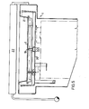
- a griddle 2 is carried via a plurality of supports 19 by a substructure 20.
- a substructure 20 Around the griddle 2 there is an upstanding wall 21, which is suitably attached to the griddle 2 by melding.
- reflector boxes 1B and insulation In the space between the griddle 2 and substructure 20 there is room for reflector boxes 1B and insulation.
- a pivotable cover 22 At a distance above the griddle 2.
- heat source With a heat source according to the illustrated embodiment there is obtained an embodiment which facilitates repairs, where one or more heating elements can be easily changed as needed.
- Other embodiments and other heat sources may also be used, of course.
- the griddle 2 is instead thereof provided with a heat source 3 for heating the griddle from the inside.
- the lower layer 8 By forming the lower layer 8 with large thickness, it may be made to form a body which is very stable as to its form at different temperatures. This body can be given a high degree of flatness on its upper side, e.g. by suitable machining.
- the material in the lower layer may suitably be a metal or metal alloy having good heat conductivity, but other materials e.g. composite material with good heat conductivity may also come into question.
- a suitable material is aluminium, for example.
- the lower layer is many times thicker than the upper layer.
- a suitable relationship is that the upper layer thickness attains to at most 10% of the lower layer thickness. It is often suitable that the thickness of the upper layer attains to only about 1% of that of the lower layer.
- the upper layer 7 may be of stainless chromium steel or other stainless alloy which is sprayed in a molten state on the lower layer 8, which is suitably of aluminium.
- the lower layer 8 has a thickness of about 25 mm of aluminium, a thickness of about 0.25 mm stainless chromium steel has been found to be suitable for the upper layer, with a size of griddle of about D.6 x 1.0 m.
- Elongate electric heating elements 16 are used to advantage as heat source 3, these elements being arranged in a suitable number in the lower layer 8 for transferring heat to it via conduction. These heating elements 16 may have a shape of the type indicated in Figure 7, and may be cast into the lower layer 8 on its production. There is thus ensured good heat transfer, but repairs will be difficult to carry out.
- An alternative is to arrange channels in the lower layer 8 instead, and to insert the heating elements into them. For improving the heat transfer in this case, and to make fusion more difficult a suitable agent can be introduced into possible intermediate space.
- FIG. 8 An alternative heat source 3 is indicated in Figure 8, where the lower layer 8 is provided with a plurality of channels 25 in which there flows a heated medium, e.g. oil or air, which is supplied via a line 26.
- a heated medium e.g. oil or air
- the griddle 2 is provided on its underside with a plurality of supports 19 for fixing it to the substructure of a griddle table in a manner corresponding to the one illustrated in Figure 5.
- These supports 19 can to advantage be made integrally with the lower layer 8.
Landscapes
- Engineering & Computer Science (AREA)
- Food Science & Technology (AREA)
- Baking, Grill, Roasting (AREA)
Applications Claiming Priority (4)
| Application Number | Priority Date | Filing Date | Title |
|---|---|---|---|
| SE8501430A SE447416B (sv) | 1985-03-22 | 1985-03-22 | Anordning for matberedning |
| SE8501430 | 1985-03-22 | ||
| SE8600690A SE465450B (sv) | 1985-03-22 | 1986-02-17 | Anordning foer matberedning innefattande stekhaell |
| SE8600690 | 1986-02-17 |
Publications (2)
| Publication Number | Publication Date |
|---|---|
| EP0197905A1 true EP0197905A1 (fr) | 1986-10-15 |
| EP0197905B1 EP0197905B1 (fr) | 1992-02-26 |
Family
ID=26658915
Family Applications (1)
| Application Number | Title | Priority Date | Filing Date |
|---|---|---|---|
| EP86850102A Expired - Lifetime EP0197905B1 (fr) | 1985-03-22 | 1986-03-20 | Surface de cuisson |
Country Status (2)
| Country | Link |
|---|---|
| EP (1) | EP0197905B1 (fr) |
| DE (1) | DE3683948D1 (fr) |
Cited By (9)
| Publication number | Priority date | Publication date | Assignee | Title |
|---|---|---|---|---|
| EP0697185A1 (fr) * | 1994-08-18 | 1996-02-21 | Middleby Marshall Inc. | Gril pour la restauration construit d'une façon modulaire et sensible à la charge |
| US5619910A (en) * | 1996-01-04 | 1997-04-15 | Keating Of Chicago, Inc. | Laminated griddle top |
| US5676043A (en) * | 1995-10-03 | 1997-10-14 | Best; Willie H. | Griddle assembly having discrete cooking zones |
| EP0967837A1 (fr) * | 1998-06-25 | 1999-12-29 | Thermocompact | Element chauffant pour applications alimentaires, et procédé pour sa fabrication |
| US6073542A (en) * | 1998-01-20 | 2000-06-13 | Perez; Primitivo | Portable gas and electric griddle for outdoor-indoor applications |
| US6138554A (en) * | 1999-03-12 | 2000-10-31 | Gas Research Institute | Multi-layer griddle |
| FR2938416A1 (fr) * | 2008-11-19 | 2010-05-21 | Frima Sa | Appareil de cuisson comprenant un materiau multicouche et un element chauffant a couche epaisse. |
| US8450654B2 (en) | 2008-10-31 | 2013-05-28 | Unified Brands, Inc. | Method and apparatus for transferring heat to a surface |
| FR3087331A1 (fr) * | 2018-10-17 | 2020-04-24 | Eric Pierre Guy Cousse | Dispositif de cuisson d'aliment par contact bi-energie electrique/gaz de type plancha ou teppanyaki |
Families Citing this family (2)
| Publication number | Priority date | Publication date | Assignee | Title |
|---|---|---|---|---|
| WO2015062859A1 (fr) | 2013-11-04 | 2015-05-07 | BSH Hausgeräte GmbH | Dispositif de cuisson équipé d'une plaque de chauffage |
| KR102254514B1 (ko) * | 2019-11-18 | 2021-05-21 | (주)바이오니아 | 발열도료를 이용한 전기그릴 |
Citations (11)
| Publication number | Priority date | Publication date | Assignee | Title |
|---|---|---|---|---|
| DE213454C (fr) * | ||||
| US1879212A (en) * | 1928-12-22 | 1932-09-27 | Hainlen Adolf | Apparatus for cooking or frying |
| GB436229A (en) * | 1934-04-07 | 1935-10-07 | William Herbert Hatfield | Improvements in or relating to cooking or heating utensils made of stainless steel |
| US2351130A (en) * | 1941-07-21 | 1944-06-13 | Majestic Mfg Company | Griddle plate |
| US2899888A (en) * | 1959-08-18 | Combined waffle bakir and grill | ||
| GB895863A (en) * | 1958-09-17 | 1962-05-09 | Sunbeam Corp | Method and apparatus for manufacturing composite metal articles |
| GB895862A (en) * | 1958-03-25 | 1962-05-09 | Sunbeam Corp | Electric cooking vessel |
| US3050834A (en) * | 1959-04-27 | 1962-08-28 | Allegheny Ludlum Steel | Composite metal article |
| US3245462A (en) * | 1963-08-01 | 1966-04-12 | Speedster Inc | Heavy duty griddle top |
| US3317709A (en) * | 1964-05-11 | 1967-05-02 | Mc Graw Edison Co | Electric griddle |
| DE1579652A1 (de) * | 1966-01-26 | 1970-10-29 | Stumpp & Schuele Kg | Elektrisch beheiztes Koch-,Brat- und Backgeraet |
-
1986
- 1986-03-20 DE DE8686850102T patent/DE3683948D1/de not_active Expired - Fee Related
- 1986-03-20 EP EP86850102A patent/EP0197905B1/fr not_active Expired - Lifetime
Patent Citations (11)
| Publication number | Priority date | Publication date | Assignee | Title |
|---|---|---|---|---|
| DE213454C (fr) * | ||||
| US2899888A (en) * | 1959-08-18 | Combined waffle bakir and grill | ||
| US1879212A (en) * | 1928-12-22 | 1932-09-27 | Hainlen Adolf | Apparatus for cooking or frying |
| GB436229A (en) * | 1934-04-07 | 1935-10-07 | William Herbert Hatfield | Improvements in or relating to cooking or heating utensils made of stainless steel |
| US2351130A (en) * | 1941-07-21 | 1944-06-13 | Majestic Mfg Company | Griddle plate |
| GB895862A (en) * | 1958-03-25 | 1962-05-09 | Sunbeam Corp | Electric cooking vessel |
| GB895863A (en) * | 1958-09-17 | 1962-05-09 | Sunbeam Corp | Method and apparatus for manufacturing composite metal articles |
| US3050834A (en) * | 1959-04-27 | 1962-08-28 | Allegheny Ludlum Steel | Composite metal article |
| US3245462A (en) * | 1963-08-01 | 1966-04-12 | Speedster Inc | Heavy duty griddle top |
| US3317709A (en) * | 1964-05-11 | 1967-05-02 | Mc Graw Edison Co | Electric griddle |
| DE1579652A1 (de) * | 1966-01-26 | 1970-10-29 | Stumpp & Schuele Kg | Elektrisch beheiztes Koch-,Brat- und Backgeraet |
Cited By (11)
| Publication number | Priority date | Publication date | Assignee | Title |
|---|---|---|---|---|
| EP0697185A1 (fr) * | 1994-08-18 | 1996-02-21 | Middleby Marshall Inc. | Gril pour la restauration construit d'une façon modulaire et sensible à la charge |
| US5676043A (en) * | 1995-10-03 | 1997-10-14 | Best; Willie H. | Griddle assembly having discrete cooking zones |
| US5619910A (en) * | 1996-01-04 | 1997-04-15 | Keating Of Chicago, Inc. | Laminated griddle top |
| US6073542A (en) * | 1998-01-20 | 2000-06-13 | Perez; Primitivo | Portable gas and electric griddle for outdoor-indoor applications |
| EP0967837A1 (fr) * | 1998-06-25 | 1999-12-29 | Thermocompact | Element chauffant pour applications alimentaires, et procédé pour sa fabrication |
| FR2780263A1 (fr) * | 1998-06-25 | 1999-12-31 | Thermocompact Sa | Element chauffant pour applications alimentaires, et procede pour sa fabrication |
| US6138554A (en) * | 1999-03-12 | 2000-10-31 | Gas Research Institute | Multi-layer griddle |
| US8450654B2 (en) | 2008-10-31 | 2013-05-28 | Unified Brands, Inc. | Method and apparatus for transferring heat to a surface |
| FR2938416A1 (fr) * | 2008-11-19 | 2010-05-21 | Frima Sa | Appareil de cuisson comprenant un materiau multicouche et un element chauffant a couche epaisse. |
| EP2190259A1 (fr) | 2008-11-19 | 2010-05-26 | Frima Sa | Ustensile de cuisine avec paroi en matérial multi-couches |
| FR3087331A1 (fr) * | 2018-10-17 | 2020-04-24 | Eric Pierre Guy Cousse | Dispositif de cuisson d'aliment par contact bi-energie electrique/gaz de type plancha ou teppanyaki |
Also Published As
| Publication number | Publication date |
|---|---|
| EP0197905B1 (fr) | 1992-02-26 |
| DE3683948D1 (de) | 1992-04-02 |
Similar Documents
| Publication | Publication Date | Title |
|---|---|---|
| EP0197905B1 (fr) | Surface de cuisson | |
| CA1260281A (fr) | Contenant de cuisson | |
| CA1306512C (fr) | Appareil servant a la preparation de repas legers tels que quiches, omelettes ou autres | |
| US4574777A (en) | Frying pan | |
| US3445630A (en) | Composite cooking vessels | |
| US20050040171A1 (en) | Multi clad cookware | |
| DE602005005680T2 (de) | Vorrichtung zum beibehalten einer temperatur in nahrungsmitteln und getränken | |
| US2967134A (en) | Process of producing cooking utensils | |
| AU743419B2 (en) | Cooking utensils | |
| CA1122637A (fr) | Appareil du cuisson pourvu d'un systeme chauffant tubulaire plat | |
| CA1044478A (fr) | Articles de cuisson auxquels les aliments ne collent pas | |
| CN219629386U (zh) | 一种易清洗内锅 | |
| JPS5911436Y2 (ja) | 電磁調理器用非金属製容器 | |
| US2494266A (en) | Cooking utensil and method | |
| US2465608A (en) | Method of producing copperplated culinary vessels | |
| US4691690A (en) | Frying device | |
| CN208784370U (zh) | 锅具及烹饪器具 | |
| US6140611A (en) | Process for supplying heat to an object and container for keeping dishes hot and reheating dishes | |
| JPS63104752A (ja) | 連続鋳造用鋳型の表面処理方法 | |
| CN219629385U (zh) | 一种易清洗内锅 | |
| JPH07255607A (ja) | 調理器具 | |
| JPH08206004A (ja) | 電磁誘導加熱用調理容器およびその製造法 | |
| GB2241873A (en) | A cooking device having heat energy regulator | |
| SU1729467A1 (ru) | Посуда дл тепловой обработки пищевых продуктов | |
| RU1777810C (ru) | Многослойный материал дл изготовлени кухонной посуды |
Legal Events
| Date | Code | Title | Description |
|---|---|---|---|
| PUAI | Public reference made under article 153(3) epc to a published international application that has entered the european phase |
Free format text: ORIGINAL CODE: 0009012 |
|
| AK | Designated contracting states |
Kind code of ref document: A1 Designated state(s): BE CH DE GB IT LI NL SE |
|
| 17P | Request for examination filed |
Effective date: 19870413 |
|
| 17Q | First examination report despatched |
Effective date: 19890510 |
|
| GRAA | (expected) grant |
Free format text: ORIGINAL CODE: 0009210 |
|
| AK | Designated contracting states |
Kind code of ref document: B1 Designated state(s): BE CH DE GB IT LI NL SE |
|
| PG25 | Lapsed in a contracting state [announced via postgrant information from national office to epo] |
Ref country code: IT Free format text: LAPSE BECAUSE OF FAILURE TO SUBMIT A TRANSLATION OF THE DESCRIPTION OR TO PAY THE FEE WITHIN THE PRE;WARNING: LAPSES OF ITALIAN PATENTS WITH EFFECTIVE DATE BEFORE 2007 MAY HAVE OCCURRED AT ANY TIME BEFORE 2007. THE CORRECT EFFECTIVE DATE MAY BE DIFFERENT FROM THE ONE RECORDED.SCRIBED TIME-LIMIT Effective date: 19920226 Ref country code: NL Effective date: 19920226 Ref country code: LI Effective date: 19920226 Ref country code: CH Effective date: 19920226 Ref country code: BE Effective date: 19920226 |
|
| PGFP | Annual fee paid to national office [announced via postgrant information from national office to epo] |
Ref country code: DE Payment date: 19920320 Year of fee payment: 7 |
|
| PGFP | Annual fee paid to national office [announced via postgrant information from national office to epo] |
Ref country code: SE Payment date: 19920325 Year of fee payment: 7 |
|
| PGFP | Annual fee paid to national office [announced via postgrant information from national office to epo] |
Ref country code: GB Payment date: 19920327 Year of fee payment: 7 |
|
| REF | Corresponds to: |
Ref document number: 3683948 Country of ref document: DE Date of ref document: 19920402 |
|
| REG | Reference to a national code |
Ref country code: CH Ref legal event code: PL |
|
| NLV1 | Nl: lapsed or annulled due to failure to fulfill the requirements of art. 29p and 29m of the patents act | ||
| PLBE | No opposition filed within time limit |
Free format text: ORIGINAL CODE: 0009261 |
|
| STAA | Information on the status of an ep patent application or granted ep patent |
Free format text: STATUS: NO OPPOSITION FILED WITHIN TIME LIMIT |
|
| 26N | No opposition filed | ||
| PG25 | Lapsed in a contracting state [announced via postgrant information from national office to epo] |
Ref country code: GB Effective date: 19930320 |
|
| PG25 | Lapsed in a contracting state [announced via postgrant information from national office to epo] |
Ref country code: SE Effective date: 19930321 |
|
| GBPC | Gb: european patent ceased through non-payment of renewal fee |
Effective date: 19930320 |
|
| PG25 | Lapsed in a contracting state [announced via postgrant information from national office to epo] |
Ref country code: DE Effective date: 19931201 |
|
| EUG | Se: european patent has lapsed |
Ref document number: 86850102.4 Effective date: 19931008 |