EP0198085B1 - Dispositif electromagnetique d'actionnement - Google Patents
Dispositif electromagnetique d'actionnement Download PDFInfo
- Publication number
- EP0198085B1 EP0198085B1 EP85904866A EP85904866A EP0198085B1 EP 0198085 B1 EP0198085 B1 EP 0198085B1 EP 85904866 A EP85904866 A EP 85904866A EP 85904866 A EP85904866 A EP 85904866A EP 0198085 B1 EP0198085 B1 EP 0198085B1
- Authority
- EP
- European Patent Office
- Prior art keywords
- iron core
- movable iron
- pole
- electromagnetic actuator
- face
- Prior art date
- Legal status (The legal status is an assumption and is not a legal conclusion. Google has not performed a legal analysis and makes no representation as to the accuracy of the status listed.)
- Expired
Links
Images


Classifications
-
- H—ELECTRICITY
- H01—ELECTRIC ELEMENTS
- H01F—MAGNETS; INDUCTANCES; TRANSFORMERS; SELECTION OF MATERIALS FOR THEIR MAGNETIC PROPERTIES
- H01F29/00—Variable transformers or inductances not covered by group H01F21/00
-
- H—ELECTRICITY
- H01—ELECTRIC ELEMENTS
- H01H—ELECTRIC SWITCHES; RELAYS; SELECTORS; EMERGENCY PROTECTIVE DEVICES
- H01H51/00—Electromagnetic relays
- H01H51/22—Polarised relays
- H01H51/2209—Polarised relays with rectilinearly movable armature
-
- H—ELECTRICITY
- H01—ELECTRIC ELEMENTS
- H01F—MAGNETS; INDUCTANCES; TRANSFORMERS; SELECTION OF MATERIALS FOR THEIR MAGNETIC PROPERTIES
- H01F7/00—Magnets
- H01F7/06—Electromagnets; Actuators including electromagnets
- H01F7/08—Electromagnets; Actuators including electromagnets with armatures
- H01F7/16—Rectilinearly-movable armatures
- H01F7/1607—Armatures entering the winding
- H01F7/1615—Armatures or stationary parts of magnetic circuit having permanent magnet
-
- H—ELECTRICITY
- H01—ELECTRIC ELEMENTS
- H01F—MAGNETS; INDUCTANCES; TRANSFORMERS; SELECTION OF MATERIALS FOR THEIR MAGNETIC PROPERTIES
- H01F7/00—Magnets
- H01F7/06—Electromagnets; Actuators including electromagnets
- H01F7/08—Electromagnets; Actuators including electromagnets with armatures
- H01F7/16—Rectilinearly-movable armatures
- H01F7/1638—Armatures not entering the winding
- H01F7/1646—Armatures or stationary parts of magnetic circuit having permanent magnet
-
- H—ELECTRICITY
- H01—ELECTRIC ELEMENTS
- H01F—MAGNETS; INDUCTANCES; TRANSFORMERS; SELECTION OF MATERIALS FOR THEIR MAGNETIC PROPERTIES
- H01F7/00—Magnets
- H01F7/06—Electromagnets; Actuators including electromagnets
- H01F7/08—Electromagnets; Actuators including electromagnets with armatures
- H01F7/121—Guiding or setting position of armatures, e.g. retaining armatures in their end position
- H01F7/122—Guiding or setting position of armatures, e.g. retaining armatures in their end position by permanent magnets
-
- H—ELECTRICITY
- H01—ELECTRIC ELEMENTS
- H01F—MAGNETS; INDUCTANCES; TRANSFORMERS; SELECTION OF MATERIALS FOR THEIR MAGNETIC PROPERTIES
- H01F7/00—Magnets
- H01F7/06—Electromagnets; Actuators including electromagnets
- H01F7/08—Electromagnets; Actuators including electromagnets with armatures
- H01F7/121—Guiding or setting position of armatures, e.g. retaining armatures in their end position
- H01F7/124—Guiding or setting position of armatures, e.g. retaining armatures in their end position by mechanical latch, e.g. detent
Definitions
- the present invention generally relates to an electromagnetic actuator which electrically cont- rolls mechanical force for electromagnetic devices such as electromagnetic relay, electromagnetic switch, electromagnetic valve, electromagnetic locking means, electromagnetic brake, electromagnetic clutch, electromagnetic vibrator, or the like.
- electromagnetic actuators are generally composed of a combination of electromagnetic attraction of an electromagnet and spring bias force.
- an electromagnetic actuator with self- supporting ability is composed of an electromagnet, a spring, and a permanent magnet as a self-latching means.
- FIG. 8(a), (b) there is shown a constitution of most commonly used plunger type electromagnetic actuator in the prior art.
- This known plunger type electromagnetic actuator comprises a stationary element consisting of a stationary iron core 1 and a winding element 4 wound round the core 1, a plunger shape movable iron core 2 capable of reciprocating with respect to the iron core 1, and a spring 3 generating a bias force so as to maintain a gap 1 a between the stationary iron core 1 and the movable iron core 2 while the winding element 4 is free from an electric current.
- Fig. 8(a) shows the OFF-state of this plunger type electromagnetic actuator: the plunger shaped movable iron core 2 is facing the iron core 1 under mechanical stable condition due to the function of the spring 3 which applies its bias force in the direction shown by arrow 3a to the movable core 2.
- FIG. 9(a), (b) there is shown another conventional electromagnetic actuator which is additionally provided with a permanent magnet for latching.
- This latching type electromagnetic actuator is so constituted that the magnetomotive force of the permanent magnet 5 is applied in series to the magnetomotive force of the magnetic circuit consisting of the stationary iron core 1, the movable iron core 2 and the gap 1a as shown in Fig. 9(a), (b).
- first mechanical stable state When the winding element 4 is in the OFF-state i.e., an electric current is not flowing therethrough, the magnetic flux 26 caused by the magnetic force of the permanent magnet 5 applies an attractive force to the movable iron core 2 which is always subjected to the bias force in the direction of arrow 3a by means of the spring 3. Since this attractive force due to the permanent magnet 5 is in equilibrium with the bias force of the spring 3, the movable iron core 2 is isolated from the stationary iron core 1 with a gap 1 therebetween. This state is referred as "first mechanical stable state".
- actuating member connected to the movable iron core 2 such as an electric contact piece, valve rod or the like (not shown) can be mechanically actuated.
- the latter mentioned conventional electromagnetic actuator having the latching property shown in Fig. 9(a), (b) has the advantage that both mechanical stable states can be easily switched one to another by applying an electric current in a series of pulses in an instant so that this actuator can be controlled by a small amount of electric energy.
- this actuator since the permanent magnet 5 having a great reluctance is arranged in the magnetic circuit in series when energized by the winding element 4, this actuator requires ampere turns for energizing several times as large as the former actuator shown in Fig. 9(a), (b). So this actuator requires a great capacity of the energizing power source and/or an increase of the size of the winding element. Furthermore, this actuator has the drawback that the required values of ampere turns for switching on and off are considerably different from each other.
- JP-A-5 913 307 (Matsushita Electric Works) further discloses a similar plunger type electromagnetic device having a permanent magnet mounted in parallel in the magnetic circuit.
- the electromagnetic actuator of the present invention comprises a casing with at least an opening including a stationary iron core, at least one movable iron core capable of reciprocally moving through the opening of the casing, an electric winding element arranged in the casing for applying a first magnetomotive force to the movable iron core when energized and a permanent magnet so mounted in the casing as to apply to the movable iron core a second magnetomotive force in parallel to the first magnetomotive force.
- the actuator further comprises: a pole piece so arranged within the casing that the magnetic flux generated by the permanent magnet is divided into two flux flows at said pole piece, said pole piece having a first pole face secured to a first pole face of the permanent magnet, and a second pole face so arranged that an end face of the movable iron core can be reciprocally moved close to or apart from said second pole face; and an element made of a material capable of increasing the magnetic reluctance, interposed in the second magnetic circuit for constituting a dividing magnetic path.
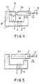
- Fig. 4 the magnetic flux generated by the permanent magnet 5 is divided into a leftside and a rightside flux 0b and 0a at a pole piece 16.
- the magnetic flux 0 is generated as an electric current is flowing through the winding element 4.
- the magnetic flux 0io is also generated as an electric current is flowing through the winding element 4.
- the actuator according to the present invention can easily generate attractive force several times as great as that of the prior art under the same condition; i.e., the same value of the energizing ampere turns in accordance with the value of a.
- the actuator of the present invention can easily generate the same value of the attractive force as that of the prior art at a small value of ampere turns in comparison with the prior art.
- the electromagnetic actuator according to the invention can provide the following excellent results in comparison with the conventional devices.
- a first pole face of N-polarity of a permanent magnet 5 is fixed to a first pole face of a pole piece 16.
- a movable iron core 2 is so arranged that one end face 2a of the core 2 can be reciprocally moved close to or apart from a second pole face 16a of the pole piece 16.
- a stationary iron core 1 has a first pole face 1f which faces to a side surface 2b, met at right angle with the end face 2a of the movable iron core 2, through a fine gap 1 and a second pole face 11 which is fixed to the second pole face of S-polarity of the permanent magnet 5.
- a winding element 4 is so arranged in the stationary iron core 1 as to energize the magnetic circuit consisting of the stationary iron core 1, the movable iron core 2, and the pole piece 16 and the dividing magnetic path element 17.
- a spring (not shown) is also interposed between the movable iron core 2 and the pole piece 16 in order to apply the bias force to the movable iron core 2.
- the spring may be interposed between the movable iron core 2 and the stationary iron core 1.
- the dividing magnetic path element 17 having a required magnetic reluctance is interposed between a third pole face 16b of the pole piece 16 and a third pole face 1 k of the stationary iron core 1.
- Fig. 1(a) shows a first mechanical stable state where an electric current is not flowed through the winding element 4. That is, the bias force caused by the spring exists in equilibrium with the attractive force of the magnetic flux 0 a owing to the magnetomotive force of the permanent magnet 5 so that the movable iron core 2 is maintained in the position where a required space is defined between the end face 2a of the movable iron core 2 and the pole face 16a of the pole piece 16.
- FIG. 2 there is shown another embodiment of the electromagnetic actuator according to the present invention.
- This embodiment is constituted substantially identical to the first embodiment except for the following points.
- a pair of movable iron cores 2 is connected through a non-magnetic connecting rod 8 and is so arranged that an inner end face 2a of each the movable iron cores 2 can be moved close to or apart from a second pole face 16a of a pole piece 16.
- a stationary iron core 1 has a pair of first pole faces 1f facing to the side surface 2b met at right angle with the inner end face 2a of the movable iron core 2 through a fine gap 1n and a second pole face 11 secured to a second pole face of a permanent magnet 5.
- a pair of dividing magnetic path elements 17 having the required magnetic reluctance is fixed to the outer end faces 2h of the movable iron cores 2.
- any one of the movable iron cores 2 and the dividing magnetic path elements 17 can be operated alternatively as an electric current is flowed through the winding element 4. As a result there is no means for generating mechanical bias force such as a spring 3.
- FIG. 3(a), 3(b) there is shown a further embodiment of the electromagnetic actuator according to the present invention.
- This embodiment is constituted substantially identical to the first embodiment except for the following points.
- a pole piece 16 is formed with a recess 16d as shown in the drawing.
- a movable iron core 2 is so arranged that a end 2i of the movable iron core 2 can be inserted in or drawn from the recess 16d.
- the recess 16d in the pole piece 16 may be formed as a complete through hole.
- the device according to the present invention can be utilized for various applications such as electromagnetic relay, electromagnetic valve, electric locking device, electromagnetic sieve, and so on which are compact, high sensitive, light and low-energy consuming devices capable of working a tiny power source such as a solar battery, a dry cell or the like.
Landscapes
- Physics & Mathematics (AREA)
- Electromagnetism (AREA)
- Engineering & Computer Science (AREA)
- Power Engineering (AREA)
- Electromagnets (AREA)
- Reciprocating, Oscillating Or Vibrating Motors (AREA)
Abstract
Claims (6)
et une deuxième face polaire (11) fixée à une deuxième face polaire de l'aimant permanent 5.
Priority Applications (1)
| Application Number | Priority Date | Filing Date | Title |
|---|---|---|---|
| AT85904866T ATE48048T1 (de) | 1984-10-09 | 1985-09-26 | Elektromagnetischer schalter. |
Applications Claiming Priority (4)
| Application Number | Priority Date | Filing Date | Title |
|---|---|---|---|
| JP211862/84 | 1984-10-09 | ||
| JP59211862A JPS6189608A (ja) | 1984-10-09 | 1984-10-09 | 電磁アクチユエイタ− |
| JP6599/85 | 1985-01-17 | ||
| JP659985A JPS61167367A (ja) | 1985-01-17 | 1985-01-17 | 電磁アクチユエイタ− |
Publications (3)
| Publication Number | Publication Date |
|---|---|
| EP0198085A1 EP0198085A1 (fr) | 1986-10-22 |
| EP0198085A4 EP0198085A4 (fr) | 1987-02-12 |
| EP0198085B1 true EP0198085B1 (fr) | 1989-11-15 |
Family
ID=26340787
Family Applications (1)
| Application Number | Title | Priority Date | Filing Date |
|---|---|---|---|
| EP85904866A Expired EP0198085B1 (fr) | 1984-10-09 | 1985-09-26 | Dispositif electromagnetique d'actionnement |
Country Status (7)
| Country | Link |
|---|---|
| US (1) | US4746886A (fr) |
| EP (1) | EP0198085B1 (fr) |
| KR (1) | KR880700439A (fr) |
| CN (1) | CN1003822B (fr) |
| AU (1) | AU575444B2 (fr) |
| DE (1) | DE3574307D1 (fr) |
| WO (1) | WO1986002484A1 (fr) |
Families Citing this family (21)
| Publication number | Priority date | Publication date | Assignee | Title |
|---|---|---|---|---|
| AU586630B2 (en) * | 1985-06-04 | 1989-07-20 | Iwasaki Electronics Co. Ltd. | Electromagnetic actuator |
| US4868695A (en) * | 1988-03-30 | 1989-09-19 | Magnetic Peripherals Inc. | Head/arm lock mechanism for a disk drive |
| DE4018409A1 (de) * | 1990-06-08 | 1991-12-12 | Magnet Motor Gmbh | Elektrisch betaetigbarer fahrzeug-aussenspiegel |
| DE4128983C2 (de) * | 1991-08-31 | 1996-02-29 | Harting Elektronik Gmbh | Polarisierter Hubmagnet |
| DE69322793T2 (de) * | 1992-10-14 | 1999-05-12 | Maxtor Corp., San Jose, Calif. | Passive berührungslose verriegelung |
| US5847631A (en) * | 1995-10-10 | 1998-12-08 | Georgia Tech Research Corporation | Magnetic relay system and method capable of microfabrication production |
| KR100472829B1 (ko) * | 2002-07-10 | 2005-03-10 | 학교법인 한양학원 | 보이스코일 모터 및 그 설계방법 |
| JP4625727B2 (ja) * | 2005-06-30 | 2011-02-02 | 日立オートモティブシステムズ株式会社 | 電磁アクチュエータ及びそれを用いたクラッチ機構及び自動車の動力伝達機構 |
| BRPI0600680C1 (pt) * | 2006-02-24 | 2008-04-22 | Oscar Rolando Avila Cusicanqui | aperfeiçoamento introduzido em interruptor elétrico |
| EP1975960A1 (fr) * | 2007-03-30 | 2008-10-01 | Abb Research Ltd. | Actionneur bistable magnétique, circuit de commande électronique et procédé pour faire fonctionner cet actionneur |
| FR2921199B1 (fr) * | 2007-09-17 | 2014-03-14 | Schneider Electric Ind Sas | Actionneur electromagnetique et appareil interrupteur equipe d'un tel actionneur electromagnetique |
| DE102007058188A1 (de) * | 2007-12-04 | 2009-06-10 | Fidlock Gmbh | Magnetische Kopplungsvorrichtung |
| US7969772B2 (en) * | 2008-11-18 | 2011-06-28 | Seagate Technology Llc | Magnetic mechanical switch |
| DE102009029826B4 (de) * | 2009-06-18 | 2012-01-26 | Pierburg Gmbh | Elektromagnetventil |
| EP2388793A1 (fr) * | 2010-05-21 | 2011-11-23 | ABB Research Ltd. | Actionneur, déclencheur et interrupteur |
| DE202011004021U1 (de) * | 2011-03-16 | 2012-07-09 | Eto Magnetic Gmbh | Elektromagnetische Aktuatorvorrichtung |
| DE102012107922A1 (de) * | 2012-08-28 | 2014-03-06 | Eto Magnetic Gmbh | Elektromagnetische Aktuatorvorrichtung |
| WO2014042525A1 (fr) | 2012-09-11 | 2014-03-20 | Nederlandse Organisatie Voor Toegepast-Natuurwetenschappelijk Onderzoek Tno | Transducteur à réluctance |
| DE202012009830U1 (de) * | 2012-10-15 | 2012-11-15 | Bürkert Werke GmbH | Impulsmagnetventil |
| CN103236376B (zh) * | 2013-03-29 | 2015-06-17 | 厦门宏发电力电器有限公司 | 一种非对称螺线管式结构的磁保持继电器 |
| EP4350983B1 (fr) * | 2021-06-30 | 2025-12-24 | Huawei Digital Power Technologies Co., Ltd. | Système photovoltaïque et appareil de protection contre les surintensités à courant continu |
Citations (1)
| Publication number | Priority date | Publication date | Assignee | Title |
|---|---|---|---|---|
| JPS54100056U (fr) * | 1977-12-27 | 1979-07-14 |
Family Cites Families (10)
| Publication number | Priority date | Publication date | Assignee | Title |
|---|---|---|---|---|
| US3783423A (en) * | 1973-01-30 | 1974-01-01 | Westinghouse Electric Corp | Circuit breaker with improved flux transfer magnetic actuator |
| US4157520A (en) * | 1975-11-04 | 1979-06-05 | Westinghouse Electric Corp. | Magnetic flux shifting ground fault trip indicator |
| JPS6317211Y2 (fr) * | 1980-03-31 | 1988-05-16 | ||
| JPH0134326Y2 (fr) * | 1981-04-22 | 1989-10-19 | ||
| JPS57186312A (en) * | 1981-05-11 | 1982-11-16 | Kamiya Denshi Kogyo Kk | Bistable keep solenoid |
| JPS57195807U (fr) * | 1981-06-09 | 1982-12-11 | ||
| JPS5828850A (ja) * | 1981-08-12 | 1983-02-19 | Fujitsu Ltd | 半導体装置の製造方法 |
| JPS5840809U (ja) * | 1981-09-12 | 1983-03-17 | 住友特殊金属株式会社 | 自己保持型ソレノイド |
| JPS58116211U (ja) * | 1982-01-30 | 1983-08-08 | 株式会社広業社通信機器製作所 | ソレノイド |
| JPS5913307A (ja) * | 1982-07-14 | 1984-01-24 | Matsushita Electric Works Ltd | 薄型有極ソレノイド |
-
1985
- 1985-04-18 CN CN85102911.6A patent/CN1003822B/zh not_active Expired
- 1985-09-26 EP EP85904866A patent/EP0198085B1/fr not_active Expired
- 1985-09-26 DE DE8585904866T patent/DE3574307D1/de not_active Expired
- 1985-09-26 WO PCT/JP1985/000536 patent/WO1986002484A1/fr not_active Ceased
- 1985-09-26 AU AU49573/85A patent/AU575444B2/en not_active Ceased
- 1985-09-26 US US06/860,344 patent/US4746886A/en not_active Expired - Fee Related
-
1986
- 1986-05-09 KR KR1019860700256A patent/KR880700439A/ko not_active Withdrawn
Patent Citations (1)
| Publication number | Priority date | Publication date | Assignee | Title |
|---|---|---|---|---|
| JPS54100056U (fr) * | 1977-12-27 | 1979-07-14 |
Also Published As
| Publication number | Publication date |
|---|---|
| EP0198085A1 (fr) | 1986-10-22 |
| KR880700439A (ko) | 1988-03-15 |
| AU4957385A (en) | 1986-05-02 |
| EP0198085A4 (fr) | 1987-02-12 |
| CN1003822B (zh) | 1989-04-05 |
| DE3574307D1 (en) | 1989-12-21 |
| US4746886A (en) | 1988-05-24 |
| CN85102911A (zh) | 1986-06-10 |
| AU575444B2 (en) | 1988-07-28 |
| WO1986002484A1 (fr) | 1986-04-24 |
Similar Documents
| Publication | Publication Date | Title |
|---|---|---|
| EP0198085B1 (fr) | Dispositif electromagnetique d'actionnement | |
| US4451808A (en) | Electromagnet equipped with a moving system including a permanent magnet and designed for monostable operation | |
| US4835503A (en) | Linear proportional solenoid | |
| EP0248272B1 (fr) | Dispositif électromagnétique polarisé | |
| US4940958A (en) | Polarized electromagnetic apparatus | |
| US4797645A (en) | Electromagnetic actuator | |
| US5239277A (en) | Electromagnetic solenoid actuator | |
| EP0179911B1 (fr) | Appareil d'actionnement electromagnetique | |
| US3248499A (en) | Electro-mechanical actuator with permanent magnet | |
| EP0185769B1 (fr) | Verin electromagnetique | |
| EP0225388B1 (fr) | Activateur electromagnetique | |
| CA1283680C (fr) | Commutateurs c et commutateurs s pour micro-ondes | |
| KR910000597Y1 (ko) | 전자 액츄에이터 | |
| JP2613904B2 (ja) | 有極電磁石 | |
| US4717900A (en) | Low profile electromagnetic linear motion device | |
| JPS61167367A (ja) | 電磁アクチユエイタ− | |
| JPS591055B2 (ja) | 磁気アクチユエ−タ装置 | |
| JPS61127105A (ja) | 電磁石装置 | |
| KR910000598Y1 (ko) | 전자 액츄에이터 | |
| JP2833165B2 (ja) | アクチュエータ | |
| JPS6337583Y2 (fr) | ||
| JP2023028684A (ja) | 自己保持型プランジャを有する電磁弁装置 | |
| KR19980057738A (ko) | 푸시풀 솔레노이드 | |
| JPH10106421A (ja) | 多極形リードリレー | |
| JPWO1985004044A1 (ja) | 電磁操作装置 |
Legal Events
| Date | Code | Title | Description |
|---|---|---|---|
| PUAI | Public reference made under article 153(3) epc to a published international application that has entered the european phase |
Free format text: ORIGINAL CODE: 0009012 |
|
| 17P | Request for examination filed |
Effective date: 19860603 |
|
| AK | Designated contracting states |
Kind code of ref document: A1 Designated state(s): AT BE CH DE FR GB IT LI LU NL SE |
|
| A4 | Supplementary search report drawn up and despatched |
Effective date: 19870212 |
|
| 17Q | First examination report despatched |
Effective date: 19880629 |
|
| GRAA | (expected) grant |
Free format text: ORIGINAL CODE: 0009210 |
|
| AK | Designated contracting states |
Kind code of ref document: B1 Designated state(s): AT BE CH DE FR GB IT LI LU NL SE |
|
| PG25 | Lapsed in a contracting state [announced via postgrant information from national office to epo] |
Ref country code: LI Effective date: 19891115 Ref country code: NL Effective date: 19891115 Ref country code: SE Effective date: 19891115 Ref country code: CH Effective date: 19891115 Ref country code: BE Effective date: 19891115 Ref country code: AT Effective date: 19891115 Ref country code: IT Free format text: LAPSE BECAUSE OF FAILURE TO SUBMIT A TRANSLATION OF THE DESCRIPTION OR TO PAY THE FEE WITHIN THE PRESCRIBED TIME-LIMIT;WARNING: LAPSES OF ITALIAN PATENTS WITH EFFECTIVE DATE BEFORE 2007 MAY HAVE OCCURRED AT ANY TIME BEFORE 2007. THE CORRECT EFFECTIVE DATE MAY BE DIFFERENT FROM THE ONE RECORDED. Effective date: 19891115 |
|
| REF | Corresponds to: |
Ref document number: 48048 Country of ref document: AT Date of ref document: 19891215 Kind code of ref document: T |
|
| ET | Fr: translation filed | ||
| REF | Corresponds to: |
Ref document number: 3574307 Country of ref document: DE Date of ref document: 19891221 |
|
| REG | Reference to a national code |
Ref country code: CH Ref legal event code: PL |
|
| NLV1 | Nl: lapsed or annulled due to failure to fulfill the requirements of art. 29p and 29m of the patents act | ||
| PLBE | No opposition filed within time limit |
Free format text: ORIGINAL CODE: 0009261 |
|
| STAA | Information on the status of an ep patent application or granted ep patent |
Free format text: STATUS: NO OPPOSITION FILED WITHIN TIME LIMIT |
|
| PG25 | Lapsed in a contracting state [announced via postgrant information from national office to epo] |
Ref country code: LU Free format text: LAPSE BECAUSE OF NON-PAYMENT OF DUE FEES Effective date: 19900930 |
|
| 26N | No opposition filed | ||
| PGFP | Annual fee paid to national office [announced via postgrant information from national office to epo] |
Ref country code: FR Payment date: 19940914 Year of fee payment: 10 |
|
| PGFP | Annual fee paid to national office [announced via postgrant information from national office to epo] |
Ref country code: GB Payment date: 19950919 Year of fee payment: 11 |
|
| PGFP | Annual fee paid to national office [announced via postgrant information from national office to epo] |
Ref country code: DE Payment date: 19950920 Year of fee payment: 11 |
|
| PG25 | Lapsed in a contracting state [announced via postgrant information from national office to epo] |
Ref country code: FR Effective date: 19960531 |
|
| REG | Reference to a national code |
Ref country code: FR Ref legal event code: ST |
|
| PG25 | Lapsed in a contracting state [announced via postgrant information from national office to epo] |
Ref country code: GB Effective date: 19960926 |
|
| GBPC | Gb: european patent ceased through non-payment of renewal fee |
Effective date: 19960926 |
|
| PG25 | Lapsed in a contracting state [announced via postgrant information from national office to epo] |
Ref country code: DE Effective date: 19970603 |