EP0198109A2 - Vannes d'arrêt - Google Patents
Vannes d'arrêt Download PDFInfo
- Publication number
- EP0198109A2 EP0198109A2 EP85109454A EP85109454A EP0198109A2 EP 0198109 A2 EP0198109 A2 EP 0198109A2 EP 85109454 A EP85109454 A EP 85109454A EP 85109454 A EP85109454 A EP 85109454A EP 0198109 A2 EP0198109 A2 EP 0198109A2
- Authority
- EP
- European Patent Office
- Prior art keywords
- cover
- housing
- spindle
- support
- edge
- Prior art date
- Legal status (The legal status is an assumption and is not a legal conclusion. Google has not performed a legal analysis and makes no representation as to the accuracy of the status listed.)
- Granted
Links
Images




Classifications
-
- F—MECHANICAL ENGINEERING; LIGHTING; HEATING; WEAPONS; BLASTING
- F16—ENGINEERING ELEMENTS AND UNITS; GENERAL MEASURES FOR PRODUCING AND MAINTAINING EFFECTIVE FUNCTIONING OF MACHINES OR INSTALLATIONS; THERMAL INSULATION IN GENERAL
- F16K—VALVES; TAPS; COCKS; ACTUATING-FLOATS; DEVICES FOR VENTING OR AERATING
- F16K27/00—Construction of housing; Use of materials therefor
- F16K27/08—Guiding yokes for spindles; Means for closing housings; Dust caps, e.g. for tyre valves
-
- F—MECHANICAL ENGINEERING; LIGHTING; HEATING; WEAPONS; BLASTING
- F16—ENGINEERING ELEMENTS AND UNITS; GENERAL MEASURES FOR PRODUCING AND MAINTAINING EFFECTIVE FUNCTIONING OF MACHINES OR INSTALLATIONS; THERMAL INSULATION IN GENERAL
- F16K—VALVES; TAPS; COCKS; ACTUATING-FLOATS; DEVICES FOR VENTING OR AERATING
- F16K27/00—Construction of housing; Use of materials therefor
- F16K27/04—Construction of housing; Use of materials therefor of sliding valves
-
- F—MECHANICAL ENGINEERING; LIGHTING; HEATING; WEAPONS; BLASTING
- F16—ENGINEERING ELEMENTS AND UNITS; GENERAL MEASURES FOR PRODUCING AND MAINTAINING EFFECTIVE FUNCTIONING OF MACHINES OR INSTALLATIONS; THERMAL INSULATION IN GENERAL
- F16K—VALVES; TAPS; COCKS; ACTUATING-FLOATS; DEVICES FOR VENTING OR AERATING
- F16K3/00—Gate valves or sliding valves, i.e. cut-off apparatus with closing members having a sliding movement along the seat for opening and closing
- F16K3/30—Details
-
- F—MECHANICAL ENGINEERING; LIGHTING; HEATING; WEAPONS; BLASTING
- F16—ENGINEERING ELEMENTS AND UNITS; GENERAL MEASURES FOR PRODUCING AND MAINTAINING EFFECTIVE FUNCTIONING OF MACHINES OR INSTALLATIONS; THERMAL INSULATION IN GENERAL
- F16K—VALVES; TAPS; COCKS; ACTUATING-FLOATS; DEVICES FOR VENTING OR AERATING
- F16K41/00—Spindle sealings
- F16K41/02—Spindle sealings with stuffing-box ; Sealing rings
- F16K41/04—Spindle sealings with stuffing-box ; Sealing rings with at least one ring of rubber or like material between spindle and housing
- F16K41/043—Spindle sealings with stuffing-box ; Sealing rings with at least one ring of rubber or like material between spindle and housing for spindles which only rotate, i.e. non-rising spindles
Definitions
- the invention relates to a gate valve with a slide housing, in which a rubberized shut-off wedge which is displaceable by the spindle in the longitudinal direction of the spindle and which extends transversely to the flow is accommodated, and which has an upper, which is limited by an inwardly projecting housing edge and is adapted to the oval or oval-like outer contour of the shut-off wedge Has housing opening, which is sealed pressure-tight from the inside by a cranked inward sealing edge which engages behind the housing edge, which carries an outwardly projecting internal threaded connector into which a guide for the spindle, the spindle seal and a support abutment for the S p Indelbund locking screw is screwed.
- the flange connection screws otherwise required with a flanged-on housing cover are omitted and the cover is acted upon by the medium pressure itself in the sealing direction due to its inwardly bent sealing edge that engages behind the housing edge, so that it is always held securely in its sealing position. Since the cover is made larger than the upper housing opening by reaching behind the housing edge, it is first tilted by 900 during assembly and then threaded into the housing from above through the oval housing opening in a certain inclined position. After swiveling the cover into its installation position, it must be lifted up to its inner contact on the edge of the housing and then firmly clamped to the housing.
- a shut-off valve is known with such a lying from the inside against the housing edge cover, in which after threading the cover for further assembly, first the non-rising spindle in the Ge housing inserted and its threaded part screwed into the shut-off body, and the locking screw in the internal thread of the cover must be screwed in until it touches the spindle collar. Then the threaded spindle has to be turned back by actuating the spindle head until after the shut-off body is in contact with the housing seat, the cover is raised with the socket and locking screw and finally it is pressed into its clamping position while deforming the cover sealing ring. In this position, horizontal half-cylinder grooves in the cover and in the housing edge on both sides of the cover form a plurality of hollow cylinders into which cylinder pins are inserted as locking members for the cover and secured against slipping out by securing elements.
- the object of the invention is to simplify in a gate valve with the features of the preamble of claim 1, the installation of the cover and its bracing with the housing edge and the assembly of the other built-in parts.
- the solution to this problem is seen in the characterizing features of the claims.
- both the spindle seal between the cover spigot and the screw plug can be made by compressing the sealing ring inserted in the cover spigot, and the cover seal to the edge of the housing by pressing the edge of the cover against the inserted cover sealing ring, this elastic state of tension of the spindle and cover seal being achieved the self-locking of the screw plug connection is maintained in the long run and no springback of the cover sealing ring can occur.
- the inner threaded connector of the cover is expanded in the outer diameter to almost the inside width of the housing opening required for the outer contour of the shut-off wedge at its narrow point and the locking screw carries a recess on the inside for supporting the spindle collar and on the outside itself full-length external thread, so that in the enlarged clear cross-section of the internal thread connector, the thread required for the bracing can be accommodated at the full height of the internal thread connector, and the receiving chamber for the support
- the spindle collar is no longer below the screw plug but concentric with the thread inside the screw plug. This juxtaposition of the thread and the receiving chamber for the spindle collar allows the internal thread connector to be made considerably smaller in height despite a sufficient thread length.
- the housing cover with connecting piece can be inserted into a narrower housing opening in a position tilted by 90 °, so that the cross section of the housing can be made smaller.
- the shorter internal thread connector also reduces the overall height of the gate valve and, in addition, the expansion of the internal thread connector means that the support ring placed on the connector is also larger in diameter, so that the support feet extending downwards can be supported on the housing edge in a much larger area.
- the two retaining cams projecting outward on the internal threaded connector according to the feature of claim 3 make it possible for the cover, which is threaded into the housing by hand, to be held in a ready-for-assembly position by the guide strips of the support feet simply by screwing the support ring into the support position before the remaining parts of the gate valve, ie in particular the threaded spindle and the screw plug have been screwed in.
- the ends of the support feet lie fully on the edge of the housing in the support position and engage behind the mounting retaining cams of the internal threaded connector with their guide strips, so that the housing cover is securely carried and hands are free to push the threaded spindle through the internal threaded connector and into the spindle nut of the locking wedge screw in and finally screw the locking screw into the internal thread of the cover neck. This significantly simplifies the assembly of the gate valve.
- the support feet carry a stop at the end of the guideway so that they at Assembly of the cover cannot be unscrewed from the area of the holding cams of the internal threaded connector, and the cover is provided with projections in the area of the holding stops, which form a rotation lock for the support feet and overlap the support surfaces of the support feet in the clamping position.
- the internal thread connector according to the features of claim 5 is provided with two retaining cams offset off-center to the same side, which are engaged by retaining hooks of the two support feet when the support ring is inserted laterally into the support position .
- the raised cover neck is not locked here by turning it, but by pushing the support ring into the support position from the side.
- one or two diametrically opposed, circumferentially offset to the constriction of the housing opening and extending over the entire height of the cover connection piece can also be used as a mounting aid instead of the outwardly projecting retaining cams, according to the features of claim 6
- the support feet of the support ring, cast on the cover neck the support feet at the bottom carrying locking projections which engage in mounting recesses on the housing edge or the cover.
- the cover is threaded into the interior of the housing and then the support ring is inserted into the housing in such a way that the support feet lie in the major axis of the oval housing opening and pass through the housing opening.
- the threaded spindle is screwed in and the screw plug is screwed into the cover socket with just a few threads.
- the screw plug can be lifted together with all the built-in components attached to it so that the support ring can be rotated 90 ° until the support feet are attached to the outer longitudinal ribs of the connector.
- the support feet are centered on the small oval axis of the housing opening and overlap the housing edge with their lower support surfaces, so that when the locking screw is subsequently lowered, all installation parts are suspended on the housing ring via the support feet of the support ring.
- the locking projections on the support feet penetrate into the locking recesses of the edge of the housing or the cover, so that the support ring can no longer be rotated and the housing installation parts are securely carried by the support ring when the locking screw is screwed into the clamping position. Holding the housing components by hand or by other aids is not necessary here either.
- the support feet of the support ring have a large-area arc-shaped cross section and the housing edge carries large-area, flat abutment projections in the contact area of the two support feet.
- the two support feet with a large cross section lie snugly on the abutment projections of the housing edge and ensure reliable support when the housing cover is clamped, ie when the screw plug screwed into the cover connector is removed.
- Due to the large cross-section the support feet with the support ring can also be designed to be extremely stable and, like the housing and the cover, can be produced with cast iron sockets.
- the sealing edge of the housing cover engaging behind the housing edge has a circumferential recess which, together with an inclined circumferential recess of the housing edge, forms a largely closed sealing ring chamber for an elastic sealing ring, then the width required for supporting the sealing ring can be achieved of the inwardly projecting housing edge and thus reduce the cross section of the housing, and the cover receives a clean bearing centering when clamped to the housing by the sealing ring wedge-shaped on the inner bevel of the housing edge.
- the sealing ring is designed according to claim 9 as a standing sealing tape with two edge beads and if the sealing edge of the cover bears a stop bar lying against the edge of the housing, then the two sealing beads can deform inward when the cover is tightened via the bevel of the sealing ring chamber and ensure a secure seal of the Ensure the housing cover, whereby a metal system is achieved by the stop bar lying against the edge of the housing, which prevents the elastic sealing tape from being overloaded or squashed.
- the housing opening and the housing interior can be used even better for threading and pivoting the cover if, according to the feature of claim 10, the internal thread connection with the bottom is arranged in the cover in the direction of the bent edge of the sealing edge towards the housing. This can be done by pulling down the internal thread in the area of the elbow of the cover Reduce the installation dimension of the cover even further from the lower edge of the offset to the upper edge of the internal thread connector, so that even less space is required for installing the cover.
- the metallic screw plug according to the feature of claim 11 is provided with a good sliding property of wear-resistant plastic layer, which by overmolding the screw plug or laying on e.g. Rolling a sheath can be produced, a metallic sliding pairing between the locking screw and the threaded spindle or the spindle collar can be avoided and in a simple manner create a plastic sliding surface intimately connected to the locking screw, which both the executives and the spindle forces transmitted via the spindle collar can record safely.
- This plastic layer can also carry ring grooves in the spindle guide area, in which the spindle sealing rings can be accommodated in a simple manner.
- the gate valve shown in FIGS. 1 to 3 consists of the slide housing 1, in which a shut-off wedge 3 which can be displaced in the longitudinal direction of the spindle is accommodated.
- the locking wedge 3 is shown in the left half of the drawing of FIGS. 1 and 2 in the closed position and in the right half of the drawing in the open position.
- the slide housing 1 carries the two flanged side inlet and outlet ports 4 and 5 for the passage of the flow medium and has an inwardly projecting housing edge 6 which delimits the upper housing opening 7.
- This housing opening 7 is closely matched to the oval-like outer contour of the compact blocking wedge 3 so that the blocking wedge can be inserted into the smallest possible housing through the housing opening 7.
- the threaded part 8 of the spindle 2 is screwed into the spindle nut 9 inserted into the head of the shut-off wedge 3 and is completely immersed in the cylinder cavity of the shut-off wedge in the open position of the gate valve.
- the housing 1 is provided for guiding the locking wedge 3 with longitudinal guide strips 10 which engage in longitudinal grooves of the locking wedge.
- the upper housing opening 7 is closed by a cover 11 which bears an inwardly bent sealing edge 12 with which it engages behind the housing edge 6 from the inside.
- the housing cover 11 has an outwardly projecting In threaded neck 13, in which the screw plug 14 is screwed. Between the locking screw 14 and the cover 13, a support ring 15 is inserted, which is supported via the two diametrically opposite support feet 16 on large abutment projections 17 of the housing edge 6 and thereby the cover 11 when tightening the locking screw 14 with its sealing edge 12 and its inserted elastic sealing ring 18 presses firmly against the inside edge of the housing.
- the internal thread connector 13 is adapted in its outer diameter almost the width of the housing opening 7 at the narrow point 19 and the locking screw 14 carries a recess 20 for the spindle collar 21 so that the external thread 22 of the locking screw extends over the entire height of the cover connector 13.
- the internally threaded connector 13 is provided with two outwardly projecting mounting retaining cams 23 which lie within the cross-sectional profile of the housing opening 7 and are arranged offset to the circumference to the constriction 19, so that the cover 11 with the connector 13 is threaded into the housing in a position tilted and inclined by 90 ° the pivoting back into its installation position up to the housing edge 6 can be freely pulled up. So that the cover 11 is held in the assembly position by means of these holding cams 23, the two support feet 16 are arcuate in cross-section and carry in their lower region inwardly projecting guide strips 24 which engage behind the holding cams 23 when the support ring 15 is screwed into the support position.
- the support feet 16 are provided at the end of the guide track 25 formed by the guide strips 24 with a holding stop 26 for the holding cams 23.
- the cover 11 carries, in the region of these holding stops 26, projections 27 for securing the support feet 16 against rotation, which the support surfaces 28 of the support feet 16 overlap in the clamping position of the housing cover 11.
- the cranked sealing edge 12 of the cover 11 carries a circumferential trapezoidal groove 29 which, together with the circumferential inclined recess 30 of the housing edge 6, forms a largely closed sealing ring chamber for the elastic sealing ring 18.
- the elastic sealing ring 18 is designed as a standing sealing tape with two edge beads 31 and 32.
- the elastic stop of the sealing ring 18 is fixed by the circumferential stop bar 33 of the sealing edge 12 which delimits the trapezoidal groove 29 on the outside.
- the middle part 34 of the cover 11, which forms the bottom of the internally threaded connection 13, is arranged offset in the direction of the elbow of the sealing edge 12 in the cover.
- the screw plug 14 is encapsulated in the area of the spindle guide 35 and the spindle support 36 with a plastic layer 37 which has good sliding properties and is designed to be wear-resistant.
- This plastic layer 37 is firmly connected to the metallic screw plug 14 by spraying and is securely anchored in the metal by the recesses 38 on the spindle guide 35 and the spindle collar support 36.
- ring grooves 39 are injected into the plastic layer 37, which accommodate the spindle sealing rings 40.
- a sealing lip 41 is molded onto the plastic sheathing 37 to protect the outwardly directed end of the spindle 2, and the screw plug 14 is also coated with molded plastic in the area of its outer surfaces 42.
- the screwed into the internally threaded connector 13 external thread 22 of the screw plug 14 is formed by the inner sealing ring 43 from - sealed.
- the support surfaces 28 of the support feet 16 lie firmly on the abutment projections 17 of the housing edge 6, the stop bar 33 of the cover edge 12 from the inside firmly on the housing edge 6 and the collar 44 of the locking screw 14 firmly on the support ring 15, while a slight clearance 46 remains between the support ring 15 and the outer end face 45 of the cover neck 13.
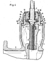
- a somewhat differently formed support ring 15 is inserted between the internal threaded connector 13 of the cover 11 and the collar 44 of the locking screw 14, in which the support ring 16 in FIGS. 1 to 3 serves as an assembly aid provided guideways and the cooperating retaining cams on the cover neck are saved.
- the support feet 16 carry locking projections 47 at the bottom, which engage in mounting recesses 48 of the housing edge 6 and form a rotation lock.
- the cover neck 13 carries two diametrically opposed outer longitudinal ribs 49, which are circumferentially offset to the constriction 19 of the housing opening 7 and which extend over the entire height of the cover neck 13.
- the screw plug 14 with the attached components can be raised, the support ring 15 rotated by 90 ° until the support feet 16 are attached to the outer longitudinal ribs 49 of the cover neck 13 and then the screw plug 14 can be lowered again somewhat, so that the support surface 28 of the support feet 16 becomes full Place it on the edge of the housing 6 and thereby all built-in parts are carried by the support ring.
- the locking projections 47 of the support feet 16 snap into the locking recesses 48 of the housing edge 6 when the locking screw 14 is lowered, rotation of the support ring 15 is reliably prevented. With this support ring suspension, the hands are free to screw the locking screw 14 into the clamping position.
- the locking screw 14 is tightened by a wrench that can be inserted into the two recesses 50.
- the outer longitudinal ribs 49 of the cover spigot 13 are arranged so that the support feet 16 are in the end position in the center of the constriction 19 of the housing opening 7.
- the support feet 16 are arcuate in cross section and the radian measure is so large that it corresponds approximately to the inside width of the housing opening 7 in the insertion position of the support ring in the housing.
- FIGS. 6 to 8 show a further possibility of the support ring formation, in which two holding cams 51 are provided on the cover neck 13 based on FIGS. 1 to 3, but which are both offset on the cover neck 13 on the same side.
- the support feet 16 of the support ring 15 here have holding hooks 52 pointing to the same side, which engage behind the two holding cams 51 and thereby hold the cover 11 in the installed position.
- the threaded cover 11 is lifted over the socket 13 and the support ring 15 is pushed with the support feet 16 from the side in the direction of the major axis of the oval housing opening 7 to the stop 53 under the retaining cam 51 of the socket 13.
- the support surfaces of the support feet 16 lie on the abutment projections 17 of the housing edge 6, so that the hands remain free for screwing in the spindle 2 and then screwing in the locking screw 14.
- the holding cams 51 are offset so far eccentrically on the cover connector 13 that they can freely pass through the housing opening 7 when the cover 11 is pulled up.
Landscapes
- Engineering & Computer Science (AREA)
- General Engineering & Computer Science (AREA)
- Mechanical Engineering (AREA)
- Valve Housings (AREA)
- Sliding Valves (AREA)
- Mechanically-Actuated Valves (AREA)
- Lift Valve (AREA)
- Acyclic And Carbocyclic Compounds In Medicinal Compositions (AREA)
- Self-Closing Valves And Venting Or Aerating Valves (AREA)
Priority Applications (1)
| Application Number | Priority Date | Filing Date | Title |
|---|---|---|---|
| AT85109454T ATE43890T1 (de) | 1984-08-03 | 1985-07-27 | Absperrschieber. |
Applications Claiming Priority (4)
| Application Number | Priority Date | Filing Date | Title |
|---|---|---|---|
| DE19843428636 DE3428636A1 (de) | 1984-08-03 | 1984-08-03 | Absperrschieber |
| DE3428636 | 1984-08-03 | ||
| DE3440464 | 1984-11-06 | ||
| DE19843440464 DE3440464A1 (de) | 1984-11-06 | 1984-11-06 | Absperrschieber |
Publications (3)
| Publication Number | Publication Date |
|---|---|
| EP0198109A2 true EP0198109A2 (fr) | 1986-10-22 |
| EP0198109A3 EP0198109A3 (en) | 1987-04-22 |
| EP0198109B1 EP0198109B1 (fr) | 1989-06-07 |
Family
ID=25823542
Family Applications (1)
| Application Number | Title | Priority Date | Filing Date |
|---|---|---|---|
| EP85109454A Expired EP0198109B1 (fr) | 1984-08-03 | 1985-07-27 | Vannes d'arrêt |
Country Status (9)
| Country | Link |
|---|---|
| US (1) | US4699359A (fr) |
| EP (1) | EP0198109B1 (fr) |
| JP (1) | JPH0784907B2 (fr) |
| DE (1) | DE3570911D1 (fr) |
| DK (1) | DK162119C (fr) |
| ES (1) | ES296088Y (fr) |
| FI (1) | FI81435C (fr) |
| IE (1) | IE56758B1 (fr) |
| NO (1) | NO155943C (fr) |
Cited By (3)
| Publication number | Priority date | Publication date | Assignee | Title |
|---|---|---|---|---|
| FR2658895A1 (fr) * | 1990-02-27 | 1991-08-30 | Hydraulique Meca Ste Nle Gle | Robinet-vanne. |
| RU2131548C1 (ru) * | 1997-10-03 | 1999-06-10 | Товарищество с ограниченной ответственностью "ТЕКСКОМП-КИТЭМА" | Задвижка (варианты) |
| RU2243436C2 (ru) * | 2001-10-31 | 2004-12-27 | Открытое акционерное общество "Икар" Курганский завод трубопроводной арматуры | Задвижка клиновая |
Families Citing this family (13)
| Publication number | Priority date | Publication date | Assignee | Title |
|---|---|---|---|---|
| US4968002A (en) * | 1989-05-03 | 1990-11-06 | American Cast Iron Pipe Company | Boltless bonnet assembly for gate valve |
| US5470046A (en) * | 1993-01-05 | 1995-11-28 | Mueller Company | Gate valve structure |
| US7000898B2 (en) * | 2003-12-09 | 2006-02-21 | Howard Tak Su Lim | Vertical shut-off valve |
| US7578496B2 (en) * | 2006-01-17 | 2009-08-25 | Allegheny Valve And Coupling, Inc. | Valve arrangement |
| JP5057914B2 (ja) * | 2007-09-25 | 2012-10-24 | 株式会社クボタ | 仕切弁 |
| US20110220828A1 (en) * | 2010-03-12 | 2011-09-15 | Penn Troy Machine Company, Inc. | Sluice gate valve |
| ES2409946T3 (es) * | 2010-11-30 | 2013-06-28 | Belgicast Internacional, S.L.U. | Sistema de válvula de compuerta con bayoneta |
| JP5502792B2 (ja) * | 2011-03-23 | 2014-05-28 | 株式会社東芝 | 蒸気弁および発電設備 |
| KR101151619B1 (ko) | 2011-05-26 | 2012-06-08 | 주식회사 한국종합기계 | 제수밸브 및 이에 구비된 디스크 |
| GB201213808D0 (en) * | 2012-08-03 | 2012-09-12 | Enston Robert P | Improved pipeline apparatus |
| US9140368B2 (en) * | 2013-03-15 | 2015-09-22 | Mueller International, Llc | Gate valve with track cleanout |
| CN103307295B (zh) * | 2013-07-05 | 2015-09-09 | 天津百利展发集团有限公司 | 低摩擦平板闸阀 |
| GB2559998B (en) | 2017-02-24 | 2019-05-08 | Pipe Transf Ltd | Pipeline apparatus with releasably lockable device |
Family Cites Families (12)
| Publication number | Priority date | Publication date | Assignee | Title |
|---|---|---|---|---|
| US1662279A (en) * | 1922-09-02 | 1928-03-13 | John C Parker | Handhole cover |
| US1783129A (en) * | 1927-05-03 | 1930-11-25 | Casey Hedges Company | Hand-hole plate |
| FR738677A (fr) * | 1931-11-21 | 1932-12-28 | Perfectionnements aux vannes à vapeur, hydrauliques et analogues | |
| US2527949A (en) * | 1946-04-23 | 1950-10-31 | Oil Well Supply Co | Slush pump valve cover |
| US2660191A (en) * | 1948-12-20 | 1953-11-24 | Alexander S Volpin | Gate valve |
| US2541968A (en) * | 1949-04-25 | 1951-02-13 | W K M Company | Gate valve |
| US2954960A (en) * | 1956-12-24 | 1960-10-04 | Acf Ind Inc | Non-floating seat structure for expanding gate valves |
| US3857546A (en) * | 1971-07-23 | 1974-12-31 | Valve Syst Int Inc | Ball valve with filament wound body |
| DE2730492C2 (de) * | 1977-07-06 | 1979-04-05 | Roetelmann & Co, 5980 Werdohl | Abdichtung für die Wellendurchführung von Rohrschaltern, insbesondere Kugelhähnen |
| US4313593A (en) * | 1979-02-20 | 1982-02-02 | Neptune Glenfield Limited | Gate valves |
| FR2492938A1 (fr) * | 1980-10-24 | 1982-04-30 | Pont A Mousson | Dispositif de fixation d'un couvercle sur un corps, notamment sur un corps de vanne |
| US20100082564A1 (en) | 2008-10-01 | 2010-04-01 | Navteq North America, Llc | Spatial Index for Locating Geographic Data Parcels Stored on Physical Storage Media |
-
1985
- 1985-07-24 NO NO852938A patent/NO155943C/no unknown
- 1985-07-27 EP EP85109454A patent/EP0198109B1/fr not_active Expired
- 1985-07-27 DE DE8585109454T patent/DE3570911D1/de not_active Expired
- 1985-08-01 DK DK348585A patent/DK162119C/da not_active IP Right Cessation
- 1985-08-01 FI FI852982A patent/FI81435C/fi not_active IP Right Cessation
- 1985-08-02 ES ES1985296088U patent/ES296088Y/es not_active Expired
- 1985-08-02 IE IE1925/85A patent/IE56758B1/en not_active IP Right Cessation
- 1985-08-02 JP JP60169941A patent/JPH0784907B2/ja not_active Expired - Fee Related
- 1985-08-05 US US06/762,775 patent/US4699359A/en not_active Expired - Lifetime
Cited By (4)
| Publication number | Priority date | Publication date | Assignee | Title |
|---|---|---|---|---|
| FR2658895A1 (fr) * | 1990-02-27 | 1991-08-30 | Hydraulique Meca Ste Nle Gle | Robinet-vanne. |
| EP0445020A1 (fr) * | 1990-02-27 | 1991-09-04 | Societe Nouvelle Generale D'hydraulique Et De Mecanique G.H.M. | Robinet-vanne |
| RU2131548C1 (ru) * | 1997-10-03 | 1999-06-10 | Товарищество с ограниченной ответственностью "ТЕКСКОМП-КИТЭМА" | Задвижка (варианты) |
| RU2243436C2 (ru) * | 2001-10-31 | 2004-12-27 | Открытое акционерное общество "Икар" Курганский завод трубопроводной арматуры | Задвижка клиновая |
Also Published As
| Publication number | Publication date |
|---|---|
| IE56758B1 (en) | 1991-12-04 |
| EP0198109B1 (fr) | 1989-06-07 |
| FI81435B (fi) | 1990-06-29 |
| ES296088Y (es) | 1988-01-16 |
| DE3570911D1 (en) | 1989-07-13 |
| US4699359A (en) | 1987-10-13 |
| FI81435C (fi) | 1990-10-10 |
| NO852938L (no) | 1986-02-04 |
| EP0198109A3 (en) | 1987-04-22 |
| DK348585A (da) | 1986-02-04 |
| DK348585D0 (da) | 1985-08-01 |
| NO155943C (no) | 1987-06-24 |
| DK162119C (da) | 1992-02-17 |
| JPH0784907B2 (ja) | 1995-09-13 |
| ES296088U (es) | 1987-07-16 |
| FI852982L (fi) | 1986-02-04 |
| IE851925L (en) | 1986-02-03 |
| DK162119B (da) | 1991-09-16 |
| FI852982A0 (fi) | 1985-08-01 |
| NO155943B (no) | 1987-03-16 |
| JPS6182081A (ja) | 1986-04-25 |
Similar Documents
| Publication | Publication Date | Title |
|---|---|---|
| EP0198109B1 (fr) | Vannes d'arrêt | |
| DE69003344T2 (de) | Rückschlagventil. | |
| DE4237674A1 (de) | Rohrschelle | |
| EP1870526B1 (fr) | Robinet sanitaire | |
| DE1942140A1 (de) | Kegelbahn | |
| DE4341087C2 (de) | Abgedichtete Schaltvorrichtung | |
| DE29703227U1 (de) | Schnellmontagetopf für Möbelscharniere | |
| DE3805970A1 (de) | Schraubanschlussvorrichtung fuer elektrische draehte und klemmschuhe | |
| DE9317983U1 (de) | Element zum Befestigen an einer hinterschnittenen Öffnung | |
| DE3440464A1 (de) | Absperrschieber | |
| DE2900601A1 (de) | Absperrorgan | |
| DE3428636A1 (de) | Absperrschieber | |
| EP4047219B1 (fr) | Unité de montage pourvu d'au moins un rail de montage, ainsi qu'au moins un clip de retenue | |
| EP0052803A2 (fr) | Bras de charnière ayant une plaque de montage | |
| DE3737162C2 (fr) | ||
| DE9017255U1 (de) | Wasserkasten mit einer Ablaßschraube | |
| EP0314823B1 (fr) | Soupape avec couvercle sans vis | |
| DE3022698C2 (fr) | ||
| DE9007585U1 (de) | Einrastbare Gewindemutter | |
| DE4128007C2 (de) | Sicherheitsventil | |
| EP1838928B1 (fr) | Robinetterie sanitaire dotee d'un dispositif de raccordement servant a raccorder un corps de sortie d'eau a un element fonctionnel | |
| DE3513538A1 (de) | Stopfen | |
| DE8808329U1 (de) | Spannring | |
| DE3601615C1 (en) | Tapping fitting or repair clamp | |
| DE3904773C2 (fr) |
Legal Events
| Date | Code | Title | Description |
|---|---|---|---|
| PUAI | Public reference made under article 153(3) epc to a published international application that has entered the european phase |
Free format text: ORIGINAL CODE: 0009012 |
|
| AK | Designated contracting states |
Kind code of ref document: A2 Designated state(s): AT BE CH DE FR GB IT LI LU NL SE |
|
| PUAL | Search report despatched |
Free format text: ORIGINAL CODE: 0009013 |
|
| AK | Designated contracting states |
Kind code of ref document: A3 Designated state(s): AT BE CH DE FR GB IT LI LU NL SE |
|
| 17P | Request for examination filed |
Effective date: 19871020 |
|
| 17Q | First examination report despatched |
Effective date: 19881118 |
|
| GRAA | (expected) grant |
Free format text: ORIGINAL CODE: 0009210 |
|
| AK | Designated contracting states |
Kind code of ref document: B1 Designated state(s): AT BE CH DE FR GB IT LI LU NL SE |
|
| PG25 | Lapsed in a contracting state [announced via postgrant information from national office to epo] |
Ref country code: BE Effective date: 19890607 |
|
| REF | Corresponds to: |
Ref document number: 43890 Country of ref document: AT Date of ref document: 19890615 Kind code of ref document: T |
|
| REF | Corresponds to: |
Ref document number: 3570911 Country of ref document: DE Date of ref document: 19890713 |
|
| PG25 | Lapsed in a contracting state [announced via postgrant information from national office to epo] |
Ref country code: LU Free format text: LAPSE BECAUSE OF NON-PAYMENT OF DUE FEES Effective date: 19890731 |
|
| ITF | It: translation for a ep patent filed | ||
| ET | Fr: translation filed | ||
| GBT | Gb: translation of ep patent filed (gb section 77(6)(a)/1977) | ||
| PLBE | No opposition filed within time limit |
Free format text: ORIGINAL CODE: 0009261 |
|
| STAA | Information on the status of an ep patent application or granted ep patent |
Free format text: STATUS: NO OPPOSITION FILED WITHIN TIME LIMIT |
|
| 26N | No opposition filed | ||
| REG | Reference to a national code |
Ref country code: CH Ref legal event code: PFA Free format text: BOPP & REUTHER AKTIENGESELLSCHAFT |
|
| NLS | Nl: assignments of ep-patents |
Owner name: BOPP & REUTHER AKTIENGESELLSCHAFT TE MANNHEIM, BON |
|
| ITTA | It: last paid annual fee | ||
| EAL | Se: european patent in force in sweden |
Ref document number: 85109454.0 |
|
| REG | Reference to a national code |
Ref country code: GB Ref legal event code: IF02 |
|
| PGFP | Annual fee paid to national office [announced via postgrant information from national office to epo] |
Ref country code: GB Payment date: 20020523 Year of fee payment: 18 |
|
| PGFP | Annual fee paid to national office [announced via postgrant information from national office to epo] |
Ref country code: DE Payment date: 20020620 Year of fee payment: 18 |
|
| PGFP | Annual fee paid to national office [announced via postgrant information from national office to epo] |
Ref country code: CH Payment date: 20020710 Year of fee payment: 18 |
|
| PGFP | Annual fee paid to national office [announced via postgrant information from national office to epo] |
Ref country code: SE Payment date: 20020712 Year of fee payment: 18 |
|
| PGFP | Annual fee paid to national office [announced via postgrant information from national office to epo] |
Ref country code: AT Payment date: 20020731 Year of fee payment: 18 Ref country code: NL Payment date: 20020731 Year of fee payment: 18 |
|
| PG25 | Lapsed in a contracting state [announced via postgrant information from national office to epo] |
Ref country code: GB Free format text: LAPSE BECAUSE OF NON-PAYMENT OF DUE FEES Effective date: 20030727 Ref country code: AT Free format text: LAPSE BECAUSE OF NON-PAYMENT OF DUE FEES Effective date: 20030727 |
|
| PG25 | Lapsed in a contracting state [announced via postgrant information from national office to epo] |
Ref country code: SE Free format text: LAPSE BECAUSE OF NON-PAYMENT OF DUE FEES Effective date: 20030728 |
|
| PGFP | Annual fee paid to national office [announced via postgrant information from national office to epo] |
Ref country code: FR Payment date: 20030728 Year of fee payment: 19 |
|
| PG25 | Lapsed in a contracting state [announced via postgrant information from national office to epo] |
Ref country code: LI Free format text: LAPSE BECAUSE OF NON-PAYMENT OF DUE FEES Effective date: 20030731 Ref country code: CH Free format text: LAPSE BECAUSE OF NON-PAYMENT OF DUE FEES Effective date: 20030731 |
|
| PG25 | Lapsed in a contracting state [announced via postgrant information from national office to epo] |
Ref country code: DE Free format text: LAPSE BECAUSE OF THE APPLICANT RENOUNCES Effective date: 20040116 |
|
| PG25 | Lapsed in a contracting state [announced via postgrant information from national office to epo] |
Ref country code: NL Free format text: LAPSE BECAUSE OF NON-PAYMENT OF DUE FEES Effective date: 20040201 |
|
| EUG | Se: european patent has lapsed | ||
| REG | Reference to a national code |
Ref country code: CH Ref legal event code: PL |
|
| GBPC | Gb: european patent ceased through non-payment of renewal fee |
Effective date: 20030727 |
|
| NLV4 | Nl: lapsed or anulled due to non-payment of the annual fee |
Effective date: 20040201 |
|
| PG25 | Lapsed in a contracting state [announced via postgrant information from national office to epo] |
Ref country code: FR Free format text: LAPSE BECAUSE OF NON-PAYMENT OF DUE FEES Effective date: 20050331 |
|
| REG | Reference to a national code |
Ref country code: FR Ref legal event code: ST |