EP0198460A2 - Module de commutation à coupe-circuit fusible - Google Patents
Module de commutation à coupe-circuit fusible Download PDFInfo
- Publication number
- EP0198460A2 EP0198460A2 EP86105106A EP86105106A EP0198460A2 EP 0198460 A2 EP0198460 A2 EP 0198460A2 EP 86105106 A EP86105106 A EP 86105106A EP 86105106 A EP86105106 A EP 86105106A EP 0198460 A2 EP0198460 A2 EP 0198460A2
- Authority
- EP
- European Patent Office
- Prior art keywords
- lock
- rocker switch
- switch
- housing
- plug
- Prior art date
- Legal status (The legal status is an assumption and is not a legal conclusion. Google has not performed a legal analysis and makes no representation as to the accuracy of the status listed.)
- Granted
Links
Images

Classifications
-
- H—ELECTRICITY
- H01—ELECTRIC ELEMENTS
- H01H—ELECTRIC SWITCHES; RELAYS; SELECTORS; EMERGENCY PROTECTIVE DEVICES
- H01H9/00—Details of switching devices, not covered by groups H01H1/00 - H01H7/00
- H01H9/20—Interlocking, locking, or latching mechanisms
- H01H9/28—Interlocking, locking, or latching mechanisms for locking switch parts by a key or equivalent removable member
-
- H—ELECTRICITY
- H01—ELECTRIC ELEMENTS
- H01H—ELECTRIC SWITCHES; RELAYS; SELECTORS; EMERGENCY PROTECTIVE DEVICES
- H01H85/00—Protective devices in which the current flows through a part of fusible material and this current is interrupted by displacement of the fusible material when this current becomes excessive
- H01H85/54—Protective devices wherein the fuse is carried, held, or retained by an intermediate or auxiliary part removable from the base, or used as sectionalisers
- H01H85/545—Protective devices wherein the fuse is carried, held, or retained by an intermediate or auxiliary part removable from the base, or used as sectionalisers with pivoting fuse carrier
-
- H—ELECTRICITY
- H01—ELECTRIC ELEMENTS
- H01H—ELECTRIC SWITCHES; RELAYS; SELECTORS; EMERGENCY PROTECTIVE DEVICES
- H01H85/00—Protective devices in which the current flows through a part of fusible material and this current is interrupted by displacement of the fusible material when this current becomes excessive
- H01H85/02—Details
- H01H85/24—Means for preventing insertion of incorrect fuse
Definitions
- the invention has for its object to improve the switch fuse unit of the above-mentioned known type so that it is protected against misuse when the fuse plug is removed.
- the invention solves this problem in that a plug lock (6) can be inserted and locked when the safety plug is removed from the insertion channel (5) of the rocker switch (3) in its switched-off position, the outer end of the plug lock (6) through the opening of the insertion channel (5) of the rocker switch and the opening (30) of the housing (2) protrudes outwards and completely fills the cross section of the two openings in such a way that the rocker switch (3) is secured against pivoting movement in its switched-off position.
- This ensures that the rocker switch in the switch-off position can be fixed at the same time and the insertion channel in the rocker switch is secured against improper access by the plug lock locked in the rocker switch.
- the plug lock has a cross section approximately corresponding to the free cross section of the insertion channel and extends into the area of the outer end face of the actuating handle of the rocker switch, so that the plug lock together with the actuating handle of the rocker switch the cross section of the opening of the slide channel in the rocker switch or the Fills the housing opening completely in such a way that the rocker switch is immovably fixed in its switched-off position.
- the mortise lock can consist of a longitudinally extending lock housing, the cross section of which is adapted to the insertion channel, the one in its outward end Cylinder lock containing the at its outer end. Insert opening for a key and at its inner end a control cam which can be pivoted back and forth by means of the key between a locking position and an unlocking position of the cylinder lock in the rocker switch.
- an elastic blocking zone assigned to a side wall of the lock housing is advantageous from the plane of the side wall by turning the cylinder lock with its control cam into the locking position into an opening in the plane of the adjacent side wall of the rocker switch and in front of one the opening in the side wall of the rocker switch delimiting stop surface of the rocker switch wall movable in the sense of blocking the plug lock in the rocker switch.
- the free end of the blocking zone is directed towards the outward end of the lock housing and is provided with an end face directed transversely to the longitudinal axis of the insertion channel.
- the locking tongue preferably forms a unitary part of the side wall of the lock housing, its outside in the unlocked state being approximately flush with the outside of the associated side wall of the lock housing.
- the insertion depth of the mortise lock can be limited by an extension on the top of the lock housing, which rests in the insertion position on the opening edge of the insertion channel in the rocker switch such that the free end of the locking tongue penetrates the pivoting plane of the control cam.
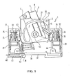
- a switch fuse unit 1 consists essentially of a housing 2, in the central cavity of which a rocker switch 3 can be pivoted about bearing pin 45 between an on and off position by means of an actuating handle 4.
- a plug lock 6 for locking the rocker switch 3 in its switched-off position is inserted into the rocker switch 3.
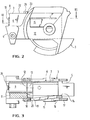
- This plug-in lock 6 sits in an insertion channel 5 (FIG. 3) of the rocker switch 3, which is normally used to receive a safety plug known per se and therefore not shown.
- the outer end face of such a safety plug which extends clockwise from the actuating handle 4 in FIG. 1 in the direction of the switch-on position, is curved in a circular cylinder and is aligned with the circular-cylindrical outer contour of the rocker switch.
- the curved end face engages under the wall surrounding the opening 30 of the switch housing 2.
- the safety plug cannot be pulled out of the rocker switch in the switched-on position; this is just possible in the off position.
- the plug lock 6 is now with its outer end far beyond the circular cylindrical circumferential contour of the rocker switch 3 to the outside up to the operating handle 4, so that the rocker switch 3 is blocked in its off position.
- the housing 2 is composed of two housing halves which are approximately mirror-symmetrical to one another, of which only one half is shown in FIG. 1.
- connection openings 27, 28 are formed for the introduction of electrical conductors, not shown in the drawing, which are to be connected to the switch fuse unit 1.
- the wall of the housing 2 lying at the top in FIG. 1 is stepped toward the end walls 25, 26.
- the upper housing wall has the opening 30, from which the operating handle 4 of the rocker switch 3 and the plug lock 6 protrude and fill the cross section of the opening 30 of the switch housing.
- the upper wall of the housing 2 has through openings 33, 34, through which the clamping screws 35, 36 located inside the housing 2 for connecting or disconnecting the electrical introduced through the connection openings 27, 28 Head operated.
- a dovetail-like groove 38 is provided on the outside thereof, the front flank of which is delimited by a quick fastening latch 39, the actuating bracket 40 of which protrudes forwardly from the end wall 25 of the housing 2.
- the quick fastener 39 is guided in a cavity 41 of the bottom wall 37 of the housing 2 in the direction of the double arrow 42.
- Each half of an insulating material, e.g. Plastic, manufactured housing 2 has a series of partitions, e.g. the partition walls 43 and 44, which cavities, i.a. also for the rocker switch, enclose and with recesses; Grooves or openings are provided to receive and hold the individual parts of the switch fuse unit 1 without screws.
- These intermediate walls extend as far as the parting plane between the two halves of the housing 2.
- Corresponding intermediate walls are present in the mirror half-symmetrical arrangement in the same way in the housing half (not shown in FIG. 1) and close to the intermediate walls of the one shown in FIG. 1 when the housing 2 is assembled shown half of the housing 2.
- the rocker switch 3 has an essentially radially extending insertion channel 5 with a rectangular cross section, which is adapted to the rectangular cross section of the longitudinally extending plug-in lock 6 inserted into the insertion channel 5 (cf. FIG. 4).
- the insertion channel 5 is surrounded by the walls of the rocker switch 3, some of which are provided with openings.
- the cuboid lock housing 7 contains in its outward end 8 a cylinder lock 9, which according to FIG. 4 has an insertion opening 11 for a key at its outer end 10.
- Fig. 3 it is shown that the cylinder lock 9 carries at its inner end 12 a control cam 13 which by means of the key between a locking position A and an unlocking position B of the cylinder lock 9 (FIGS. 5 and 6) in the rocker switch 3 back and forth swiveling f is.
- Fig. 3 it can be seen how the cylinder lock 9 arranged in the plug lock 6 cooperates with the rocker switch 3 and thereby the locking position A of the cylinder lock 9 results.
- the side wall 14 of the lock housing 7 is assigned an elastic and resilient locking tongue 15. If the plug lock is inserted into the rocker switch 3, the control cam 13 presses the locking tongue 15 out of the plane of the side wall 14 of the lock housing 7 outwards into an opening 16 in the adjacent side wall 17 of the rocker switch 3 in the locked position of the cylinder lock 9.
- the free end 19 of the locking tongue 5 is arranged in front of a stop surface 18 of the rocker switch wall 17 which delimits the opening 16 in the side wall 17 of the rocker switch 3.
- the free end 19 of the locking tongue 15 is directed toward the outward end 8 of the lock housing 7 and lies in the locking position of the cylinder lock 9 with an end face 20 which is directed transversely to the longitudinal axis of the insertion channel 5 of the rocker switch 3, the stop surface 18 of the rocker switch wall 17 across from.
- the locking tongue 15 forms a unitary part of the side wall 14 of the lock housing 7.
- the outside of the locking tongue 15 is aligned with the outside of the associated side wall 14 of the lock housing 7 (cf. also FIG. 5).
- the longitudinal axis of the cylinder lock 9 runs parallel to the longitudinal axis of the lock housing 7, but is offset in the direction of the side wall 14a of the lock housing 7 opposite the side wall 14 of the lock housing 7 and somewhat in the direction of the upper side 22 of the lock housing 7.
- the control cam 13 of the cylinder lock 9 is turned away from the locking tongue 15 by 90 °.
- the locking tongue 15 is shown in its rest position and is aligned with its outside and inside with the associated side wall 14 of the lock housing 7. This corresponds to the unlocking position B of the cylinder lock 9.
- the control cam 13 of the cylinder lock 9 is in a position which is changed by 90 ° in comparison to FIG. 5.
- the control cam 13 presses the locking tongue 15 out of its rest position outward from the plane of the side wall 14. Accordingly, the end face 20 of the locking tongue 15 is arranged outside the lock housing 7. This corresponds to the locking position A of the cylinder lock 9.
- the rocker switch 3 is brought into the off position by means of the actuating handle 4, as is shown in FIG. 1.
- the actuating handle 4 As is shown in FIG. 1.
- This plug is removed from the insertion channel 5, and the plug lock 6 is inserted into the insertion channel 5 in its place.
- the control cam is located during this insertion 13 of the cylinder lock 9 in the unlocking position B according to FIGS. 4 and 5.
- the plug-in lock 6 remaining in the insertion channel 5 prevents misuse of the switch fuse unit 1 because, on the one hand, it makes it impossible to insert a fuse plug or another object into the insertion channel of the rocker switch 3 and, on the other hand, the rocker switch 3 in the off position through the opening 30 of the housing protruding plug lock housing 7 is secured against pivoting.
Landscapes
- Fuses (AREA)
- Switch Cases, Indication, And Locking (AREA)
- Preventing Unauthorised Actuation Of Valves (AREA)
- Lock And Its Accessories (AREA)
- Coupling Device And Connection With Printed Circuit (AREA)
- Control Of Electric Motors In General (AREA)
- Details Of Connecting Devices For Male And Female Coupling (AREA)
Priority Applications (1)
| Application Number | Priority Date | Filing Date | Title |
|---|---|---|---|
| AT86105106T ATE78120T1 (de) | 1985-04-15 | 1986-04-14 | Schaltersicherungseinheit. |
Applications Claiming Priority (2)
| Application Number | Priority Date | Filing Date | Title |
|---|---|---|---|
| DE3513462A DE3513462A1 (de) | 1985-04-15 | 1985-04-15 | Schaltersicherungseinheit |
| DE3513462 | 1985-04-15 |
Publications (3)
| Publication Number | Publication Date |
|---|---|
| EP0198460A2 true EP0198460A2 (fr) | 1986-10-22 |
| EP0198460A3 EP0198460A3 (en) | 1989-03-22 |
| EP0198460B1 EP0198460B1 (fr) | 1992-07-08 |
Family
ID=6268061
Family Applications (1)
| Application Number | Title | Priority Date | Filing Date |
|---|---|---|---|
| EP86105106A Expired - Lifetime EP0198460B1 (fr) | 1985-04-15 | 1986-04-14 | Module de commutation à coupe-circuit fusible |
Country Status (3)
| Country | Link |
|---|---|
| EP (1) | EP0198460B1 (fr) |
| AT (1) | ATE78120T1 (fr) |
| DE (2) | DE3513462A1 (fr) |
Cited By (5)
| Publication number | Priority date | Publication date | Assignee | Title |
|---|---|---|---|---|
| GB2237055A (en) * | 1989-09-07 | 1991-04-24 | David Stephen Hobday | Security means for telephone distribution frames |
| WO1992016005A1 (fr) * | 1991-02-27 | 1992-09-17 | National Power Plc | Appareil pour fusibles electriques |
| FR2727808A1 (fr) * | 1994-11-19 | 1996-06-07 | Palitex Project Co Gmbh | Dispositif de commutation du sens de rotation d'un moteur electrique individuel ou de groupes de moteurs electriques |
| WO1999008303A1 (fr) * | 1997-08-07 | 1999-02-18 | Klaus Bruchmann | Fusible a codage |
| WO2001008180A1 (fr) * | 1999-07-22 | 2001-02-01 | Klaus Bruchmann | Unite de fusible a commutateur pourvue d'un verrouillage de maintien |
Families Citing this family (1)
| Publication number | Priority date | Publication date | Assignee | Title |
|---|---|---|---|---|
| DE102011087492A1 (de) * | 2011-11-30 | 2013-06-06 | Wöhner GmbH & Co. KG Elektrotechnische Systeme | Schaltvorrichtung zum Schalten eines elektrischen Bauelementes in einen Strompfad |
Family Cites Families (3)
| Publication number | Priority date | Publication date | Assignee | Title |
|---|---|---|---|---|
| DE722647C (de) * | 1941-01-09 | 1942-07-15 | Leonhard Burmann | Sicherheitsvorrichtung zum Verhueten unbefugten Einsetzens einer elektrischen Sicherung |
| DE2903826C2 (de) * | 1979-02-01 | 1985-02-14 | Lindner Gmbh, Fabrik Elektrischer Lampen Und Apparate, 8600 Bamberg | Elektrischer Einbau-Sicherungssockel für Sicherungseinsätze mit Endkontaktkappen |
| DE3406815A1 (de) * | 1984-02-24 | 1985-09-12 | Klaus 8600 Bamberg Bruchmann | Schaltersicherungseinheit |
-
1985
- 1985-04-15 DE DE3513462A patent/DE3513462A1/de active Granted
-
1986
- 1986-04-14 AT AT86105106T patent/ATE78120T1/de not_active IP Right Cessation
- 1986-04-14 DE DE8686105106T patent/DE3685899D1/de not_active Expired - Lifetime
- 1986-04-14 EP EP86105106A patent/EP0198460B1/fr not_active Expired - Lifetime
Cited By (8)
| Publication number | Priority date | Publication date | Assignee | Title |
|---|---|---|---|---|
| GB2237055A (en) * | 1989-09-07 | 1991-04-24 | David Stephen Hobday | Security means for telephone distribution frames |
| GB2237055B (en) * | 1989-09-07 | 1993-08-25 | David Stephen Hobday | Security means for telephone distribution frames |
| WO1992016005A1 (fr) * | 1991-02-27 | 1992-09-17 | National Power Plc | Appareil pour fusibles electriques |
| FR2727808A1 (fr) * | 1994-11-19 | 1996-06-07 | Palitex Project Co Gmbh | Dispositif de commutation du sens de rotation d'un moteur electrique individuel ou de groupes de moteurs electriques |
| WO1999008303A1 (fr) * | 1997-08-07 | 1999-02-18 | Klaus Bruchmann | Fusible a codage |
| WO2001008180A1 (fr) * | 1999-07-22 | 2001-02-01 | Klaus Bruchmann | Unite de fusible a commutateur pourvue d'un verrouillage de maintien |
| US6727797B1 (en) | 1999-07-22 | 2004-04-27 | Klaus Bruchmann | Fuse combination unit with maintained locking |
| CZ299011B6 (cs) * | 1999-07-22 | 2008-04-02 | Spínací pojistná jednotka |
Also Published As
| Publication number | Publication date |
|---|---|
| DE3685899D1 (de) | 1992-08-13 |
| EP0198460A3 (en) | 1989-03-22 |
| DE3513462C2 (fr) | 1988-03-24 |
| ATE78120T1 (de) | 1992-07-15 |
| DE3513462A1 (de) | 1986-10-16 |
| EP0198460B1 (fr) | 1992-07-08 |
Similar Documents
| Publication | Publication Date | Title |
|---|---|---|
| DE69837736T2 (de) | Sicherheitsschalter | |
| EP0653771A2 (fr) | Commutateur de sécurité | |
| DE3406815C2 (fr) | ||
| EP0563530B1 (fr) | Dispositif de commutation de puissance | |
| DE69932168T2 (de) | Schlüssel mit beweglichem element, schlüsselkopf und schloss | |
| EP0695472B1 (fr) | Installation de distribution electrique basse tension avec un support d'appareils et un dispositif de contact disjoncteur | |
| DE3786353T2 (de) | Verbindungsvorrichtung. | |
| DE10216594A1 (de) | Schaltschrank mit Einschubkassette | |
| EP0198460B1 (fr) | Module de commutation à coupe-circuit fusible | |
| DE3306106A1 (de) | Mehrpolige modulare schaltervorrichtung | |
| EP1246213A2 (fr) | Dispositif de commutation de puissance, de dimension 00 | |
| EP0500546B1 (fr) | Verrouillage pour un tiroir enfichable | |
| DE3741743C2 (de) | Sicherungsschalter | |
| DE69601224T2 (de) | Schalteranordnungen | |
| DE19548948C2 (de) | Schutzschalter mit gegen Einschalten sicherbarem Betätigungsgriff | |
| DE19715264B4 (de) | Einrichtung zum Plombieren und Verriegeln des Deckels eines Sicherungsschaltgerätes | |
| EP0069725B1 (fr) | Serrure mecanique, sans clef et codable | |
| DE3143638A1 (de) | Schliesszylinder | |
| EP2067152B1 (fr) | Sectionneur de sécurité à coupure en charge avec dispositif de verrouillage | |
| DE3719471C2 (fr) | ||
| DE29714134U1 (de) | Verriegelungsschieber für Sicherung | |
| AT258756B (de) | Sicherheitsschloß | |
| DE2462034C3 (de) | Zum Zusammensetzen von Tastaturen geeignete Taste | |
| AT399013B (de) | Zylinderschloss und schlüssel für dasselbe | |
| DE4037566A1 (de) | Durch ein- und ausstecken eines schluessels betaetigbares sicherheitsschaltsystem |
Legal Events
| Date | Code | Title | Description |
|---|---|---|---|
| PUAI | Public reference made under article 153(3) epc to a published international application that has entered the european phase |
Free format text: ORIGINAL CODE: 0009012 |
|
| AK | Designated contracting states |
Kind code of ref document: A2 Designated state(s): AT BE CH DE FR GB IT LI LU NL SE |
|
| PUAL | Search report despatched |
Free format text: ORIGINAL CODE: 0009013 |
|
| AK | Designated contracting states |
Kind code of ref document: A3 Designated state(s): AT BE CH DE FR GB IT LI LU NL SE |
|
| 17P | Request for examination filed |
Effective date: 19890920 |
|
| 17Q | First examination report despatched |
Effective date: 19910708 |
|
| GRAA | (expected) grant |
Free format text: ORIGINAL CODE: 0009210 |
|
| AK | Designated contracting states |
Kind code of ref document: B1 Designated state(s): AT BE CH DE FR GB IT LI LU NL SE |
|
| PG25 | Lapsed in a contracting state [announced via postgrant information from national office to epo] |
Ref country code: IT Free format text: LAPSE BECAUSE OF FAILURE TO SUBMIT A TRANSLATION OF THE DESCRIPTION OR TO PAY THE FEE WITHIN THE PRESCRIBED TIME-LIMIT;WARNING: LAPSES OF ITALIAN PATENTS WITH EFFECTIVE DATE BEFORE 2007 MAY HAVE OCCURRED AT ANY TIME BEFORE 2007. THE CORRECT EFFECTIVE DATE MAY BE DIFFERENT FROM THE ONE RECORDED. Effective date: 19920708 Ref country code: SE Effective date: 19920708 Ref country code: NL Effective date: 19920708 Ref country code: BE Effective date: 19920708 |
|
| REF | Corresponds to: |
Ref document number: 78120 Country of ref document: AT Date of ref document: 19920715 Kind code of ref document: T |
|
| REF | Corresponds to: |
Ref document number: 3685899 Country of ref document: DE Date of ref document: 19920813 |
|
| ET | Fr: translation filed | ||
| GBT | Gb: translation of ep patent filed (gb section 77(6)(a)/1977) | ||
| NLV1 | Nl: lapsed or annulled due to failure to fulfill the requirements of art. 29p and 29m of the patents act | ||
| PG25 | Lapsed in a contracting state [announced via postgrant information from national office to epo] |
Ref country code: AT Effective date: 19930414 |
|
| PG25 | Lapsed in a contracting state [announced via postgrant information from national office to epo] |
Ref country code: LU Free format text: LAPSE BECAUSE OF NON-PAYMENT OF DUE FEES Effective date: 19930430 Ref country code: LI Effective date: 19930430 Ref country code: CH Effective date: 19930430 |
|
| PLBE | No opposition filed within time limit |
Free format text: ORIGINAL CODE: 0009261 |
|
| STAA | Information on the status of an ep patent application or granted ep patent |
Free format text: STATUS: NO OPPOSITION FILED WITHIN TIME LIMIT |
|
| 26N | No opposition filed | ||
| REG | Reference to a national code |
Ref country code: CH Ref legal event code: PL |
|
| REG | Reference to a national code |
Ref country code: GB Ref legal event code: IF02 |
|
| PGFP | Annual fee paid to national office [announced via postgrant information from national office to epo] |
Ref country code: FR Payment date: 20030317 Year of fee payment: 18 |
|
| PGFP | Annual fee paid to national office [announced via postgrant information from national office to epo] |
Ref country code: GB Payment date: 20030409 Year of fee payment: 18 |
|
| PGFP | Annual fee paid to national office [announced via postgrant information from national office to epo] |
Ref country code: DE Payment date: 20030627 Year of fee payment: 18 |
|
| PG25 | Lapsed in a contracting state [announced via postgrant information from national office to epo] |
Ref country code: GB Free format text: LAPSE BECAUSE OF NON-PAYMENT OF DUE FEES Effective date: 20040414 |
|
| PG25 | Lapsed in a contracting state [announced via postgrant information from national office to epo] |
Ref country code: DE Free format text: LAPSE BECAUSE OF NON-PAYMENT OF DUE FEES Effective date: 20041103 |
|
| GBPC | Gb: european patent ceased through non-payment of renewal fee |
Effective date: 20040414 |
|
| PG25 | Lapsed in a contracting state [announced via postgrant information from national office to epo] |
Ref country code: FR Free format text: LAPSE BECAUSE OF NON-PAYMENT OF DUE FEES Effective date: 20041231 |
|
| REG | Reference to a national code |
Ref country code: FR Ref legal event code: ST |