EP0198483A2 - Platte elektrochemische Zelle mit mehreren Verbindungen - Google Patents
Platte elektrochemische Zelle mit mehreren Verbindungen Download PDFInfo
- Publication number
- EP0198483A2 EP0198483A2 EP86105229A EP86105229A EP0198483A2 EP 0198483 A2 EP0198483 A2 EP 0198483A2 EP 86105229 A EP86105229 A EP 86105229A EP 86105229 A EP86105229 A EP 86105229A EP 0198483 A2 EP0198483 A2 EP 0198483A2
- Authority
- EP
- European Patent Office
- Prior art keywords
- electrodes
- electrochemical
- electrically connecting
- membrane
- container
- Prior art date
- Legal status (The legal status is an assumption and is not a legal conclusion. Google has not performed a legal analysis and makes no representation as to the accuracy of the status listed.)
- Withdrawn
Links
Images
Classifications
-
- H—ELECTRICITY
- H01—ELECTRIC ELEMENTS
- H01M—PROCESSES OR MEANS, e.g. BATTERIES, FOR THE DIRECT CONVERSION OF CHEMICAL ENERGY INTO ELECTRICAL ENERGY
- H01M8/00—Fuel cells; Manufacture thereof
-
- F—MECHANICAL ENGINEERING; LIGHTING; HEATING; WEAPONS; BLASTING
- F04—POSITIVE - DISPLACEMENT MACHINES FOR LIQUIDS; PUMPS FOR LIQUIDS OR ELASTIC FLUIDS
- F04B—POSITIVE-DISPLACEMENT MACHINES FOR LIQUIDS; PUMPS
- F04B17/00—Pumps characterised by combination with, or adaptation to, specific driving engines or motors
-
- H—ELECTRICITY
- H01—ELECTRIC ELEMENTS
- H01M—PROCESSES OR MEANS, e.g. BATTERIES, FOR THE DIRECT CONVERSION OF CHEMICAL ENERGY INTO ELECTRICAL ENERGY
- H01M8/00—Fuel cells; Manufacture thereof
- H01M8/24—Grouping of fuel cells, e.g. stacking of fuel cells
- H01M8/241—Grouping of fuel cells, e.g. stacking of fuel cells with solid or matrix-supported electrolytes
- H01M8/2418—Grouping by arranging unit cells in a plane
-
- Y—GENERAL TAGGING OF NEW TECHNOLOGICAL DEVELOPMENTS; GENERAL TAGGING OF CROSS-SECTIONAL TECHNOLOGIES SPANNING OVER SEVERAL SECTIONS OF THE IPC; TECHNICAL SUBJECTS COVERED BY FORMER USPC CROSS-REFERENCE ART COLLECTIONS [XRACs] AND DIGESTS
- Y02—TECHNOLOGIES OR APPLICATIONS FOR MITIGATION OR ADAPTATION AGAINST CLIMATE CHANGE
- Y02E—REDUCTION OF GREENHOUSE GAS [GHG] EMISSIONS, RELATED TO ENERGY GENERATION, TRANSMISSION OR DISTRIBUTION
- Y02E60/00—Enabling technologies; Technologies with a potential or indirect contribution to GHG emissions mitigation
- Y02E60/30—Hydrogen technology
- Y02E60/50—Fuel cells
Definitions
- This invention relates generally to electrochemical devices, and, more particularly, to the arrangement of electrochemical cells.
- An electrochemical cell which typically takes the form of an electrolytic membrane positioned between and in contact with a cathode and an anode, can either generate energy (battery) or do work (pump).
- a fuel gas such as hydrogen
- a gaseous oxidant such as oxygen
- An electrical current is generated, while water is produced as a by-product.
- U.S. Patent No. 3,418,168 discloses such a single cell used to generate electricity.
- an electrical voltage is applied across the anode and cathode.
- a gas one capable of entering into an oxidation/reduction reaction, is then supplied to the anode.
- An individual electrochemical cell whether configured as a battery or a pump, generally operates at relatively small voltage and current levels.
- the small voltage prevents breakdown of the electrolytic membrane and, in addition, improves the efficiency of the cell.
- each individual cell operates at small voltage and current levels, the electrochemical device as a whole must operate at much higher voltages and currents to be compatible with standard batteries and electrical devices.
- the individual cells are mechanically stacked together, whereby adjacent cell walls are joined together. The cells are then electrically connected in series and/or parallel. This method is generally acceptable when large scale devices are contemplated. But in some applications, especially where small scale devices are required, this method becomes unacceptable. Therefore, there has been a need for an improved method of arranging the individual cells for these types of applications.
- the present invention resides in an improved arrangement of electrochemical cells wherein the individual cells are arranged on a single electrolytic membrane and contained within one chamber, with the cells electrically connected in series and/or parallel.
- This arrangement eliminates the individual cell compartments and thereby considerably reduces the bulk and weight of a mechanical stacking arrangement.
- This improved arrangement also increases cell reliability and efficiency and reduces the cost of cell manufacture.
- a three-fold increase in voltage could be achieved by a three-cell mechanical stacking arrangement, one in which three single cells are simply joined together and electrically connected in series. Although the voltage would be increased as desired, the gas flow rate, the current level and the size would also be increased by a factor of three.
- This three-cell arrangement could be miniaturized by a factor of three in order to operate at a comparable gas flow rate and current level as the three-cell improved arrangement, but not without the weight, bulk and complexity of the many compartment walls and inlet and outlet lines which would result from the miniaturized mechanical stacking arrangement. Not only does the improved arrangement reduce the weight, bulk and complexity of a mechanical stacking arrangement, but with the elimination of all but one membrane and one inlet and outlet line, also increases efficiency and reliability at a much reduced cost and with a greatly simplified manufacturing process.
- the invention is concerned with a novel arrangement of electrochemical cells.
- the voltage at which a typical cell operates is much lower than that of conventional power sources, such as dry-cell batteries.
- Stacking cells mechanically and then connecting them electrically in series solves this voltage problem, but only at the expense of increased bulk and weight, and increased gas flow.
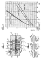
- FIG. 1 illustrates an arrangement of three electrochemical cells 10, 12 and 14 on a single electrolytic membrane 16, configured for a pump application.
- a gas-tight container 18 forms a pump chamber.
- the electrolytic membrane 16 separates the pump chamber into an inlet chamber 20 and an outlet chamber 22.
- an electrochemically active fluid contained in the inlet chamber 20 is pumped into the outlet chamber 22.
- Membrane 16 also forms the structural foundation for the three electrochemical cells 10, 12 and 14.
- the electrochemical cells 10, 12 and 14 are each comprised of a pair of conductive electrodes disposed on opposite surfaces of the electrolytic membrane 16, a pair of electrical contacts for electrically connecting the electrodes of the cells together and that portion of membrane 16 in contact with the electrodes.
- electrochemical cell 10 includes electrodes 24 and 26, electrical contacts 28 and 30 and membrane 16.
- Electrochemical cell 12 includes electrodes 32 and 34, electrical contacts 36 and 38 and membrane 16.
- Electrochemical cell 14 includes electrodes 40 and 42, electrical contacts 44 and 46 and membrane 16.
- the electrodes can be constructed of any material that is electrically conductive and acts as a catalyst in converting the gas molecules in the inlet chamber 20 to ions and reconverting those ions to gas molecules in the outlet chamber 22, in response to a voltage gradient applied across membrane 16.
- the membrane 16 can be composed of any solid-electrolyte material containing dissociated functional groups capable of transporting either cations or anions.
- the electrical contacts can be any conductive material.
- the electrochemical pump shown in FIG. 1 is easily constructed.
- the gas-tight container 18 is formed by wall segments 56 and 58. Segments 56 and 58 may be composed of any material impervious to gas, such as metal, glass or plastic. Gaskets 60 and 62 ensure gas-tight operation when the segments 56 and 58 are connected to form the container 18.
- the segment 56 includes a gas inlet 64 and a check valve 66 leading to the inlet chamber 20.
- the segment 58 includes a gas outlet 68 leading from the outlet chamber 22.
- FIG. 2 shows an electrical connection of the three electrochemical cells in a series arrangement.
- the electrical contact 28 is connected to the positive side of a suitable power source, the electrical contacts 30 and 36 are electrically connected, the electrical contacts 38 and 44 are electrically connected and the electrical contact 46 is connected to the negative side of the power source.
- the electrical connection of the contacts in this manner increases the voltage of the device by a factor of three over the voltage of the individual cells.
- the device shown in FIG. 1 operates with any reduction/oxidation material that is electrochemically reversibly active so as to react at the electrodes 24, 32 and 40 to produce ions, which will then migrate across electrolytic membrane 16 and be reconverted at the electrodes 26, 34 and 42 into a molecular state.
- Molecular hydrogen in gaseous form is one suitable example.
- an anodic reaction occurs, represented by the equation: H 2 ⁇ 2H + + 2e-
- the hydrogen molecules in the inlet chamber 20 are therefore converted into ions which move across the electrolytic membrane 16 because of the voltage gradient across the membrane.
- a cathodic reaction occurs, represented by the equation:
- the hydrogen ions are therefore reconverted into hydrogen molecules and released into the outlet chamber 22.
- FIG. 3 shows exemplary experimental results obtained with two single cells and one double cell. Voltage, in volts, is shown on the vertical axis and current, in milli- amps, is shown on the horizontal axis. First, each of the single cell currents is shown as a function of the voltage. These voltage-current curves are then added to arrive at the calculated sum curve, which should equal the experimental results of two cells in series. The two curves are similar and therefore "cross-talk" is small. This result is due in large part to a high ratio of the distance between adjacent electrodes and the thickness of the electrolytic membrane.
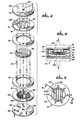
- FIGS. 4, 5 and 6 illustrate the simplicity of construction of an electrochemical pump having six electrochemical cells on a single electrolytic membrane.
- a modular electrochemical pump 70 is constructed of seven circular segments, indicated by reference numerals 72, 74, 76, 78, 80, 82 and 84.
- the middle segment 78 includes a solid electrolytic membrane. Deposited on both sides of the membrane of segment 78 is an electrode formation 86.
- the two ring-shaped segments 76 and 80 provide structural support for the membrane of segment 78.
- the next outer segments 74 and 82, also ring-shaped, have current collectors 88 and 90 and form an inlet chamber 92 and an outlet chamber 94.
- the outer segments 72 and 84 form the top and bottom walls of the pump 70.
- a voltage gradient across the membrane of segment 78 causes the electrochemically active fluid in the inlet chamber 92 to be pumped across the membrane into the outlet chamber 94.
- the outlet chamber leads to a fluid outlet 98, included in segment 84.
- the six electrochemical cells which are formed by the combination of segments 74, 78 and 82, each includes conductive electrodes and that portion of the membrane of segment 78 in contact with the electrodes.
- the electrolytic membrane of segment 78 provides the foundation upon which each of the six cells is built.
- a thin film of metal is deposited on both sides of the membrane of segment 78, in the desired shape of the electrodes, to form the electrode formation 86.
- the electrode formation 86 of the preferred embodiment, has six essentially parallel strips of metal film, each having approximately the same surface area.
- the current collectors 88 and 90 overly the electrode formation 86.
- the current collectors of the six electrochemical cells are electrically connected internally through a series of contact pins, which are inserted through holes in the outer perimeter of the segments, and metal traces deposited directly on the inner face of the outer segments 72 and 84.
- contact pin 100 provides electrical contact between metal trace 102 and metal trace 104.
- metal trace 102 is in electrical contact with a current collector 106
- metal trace 104 is in electrical contact with a current collector 108.
- the contact pins also provide alignment and structural integrity when the segments are combined.
Landscapes
- Engineering & Computer Science (AREA)
- Sustainable Energy (AREA)
- Chemical Kinetics & Catalysis (AREA)
- Life Sciences & Earth Sciences (AREA)
- Manufacturing & Machinery (AREA)
- Sustainable Development (AREA)
- General Chemical & Material Sciences (AREA)
- Chemical & Material Sciences (AREA)
- Electrochemistry (AREA)
- General Engineering & Computer Science (AREA)
- Mechanical Engineering (AREA)
- Fuel Cell (AREA)
- Electrolytic Production Of Non-Metals, Compounds, Apparatuses Therefor (AREA)
- Electromagnetic Pumps, Or The Like (AREA)
- Connection Of Batteries Or Terminals (AREA)
Applications Claiming Priority (2)
| Application Number | Priority Date | Filing Date | Title |
|---|---|---|---|
| US724912 | 1985-04-19 | ||
| US06/724,912 US4648955A (en) | 1985-04-19 | 1985-04-19 | Planar multi-junction electrochemical cell |
Publications (2)
| Publication Number | Publication Date |
|---|---|
| EP0198483A2 true EP0198483A2 (de) | 1986-10-22 |
| EP0198483A3 EP0198483A3 (de) | 1987-10-28 |
Family
ID=24912418
Family Applications (1)
| Application Number | Title | Priority Date | Filing Date |
|---|---|---|---|
| EP86105229A Withdrawn EP0198483A3 (de) | 1985-04-19 | 1986-04-16 | Platte elektrochemische Zelle mit mehreren Verbindungen |
Country Status (4)
| Country | Link |
|---|---|
| US (1) | US4648955A (de) |
| EP (1) | EP0198483A3 (de) |
| JP (2) | JP2545364B2 (de) |
| CA (1) | CA1270295A (de) |
Cited By (7)
| Publication number | Priority date | Publication date | Assignee | Title |
|---|---|---|---|---|
| DE4329819A1 (de) * | 1993-07-28 | 1995-02-02 | Fraunhofer Ges Forschung | Streifenmembran |
| WO1995004382A1 (de) * | 1993-07-28 | 1995-02-09 | Fraunhofer-Gesellschaft zur Förderung der angewandten Forschung e.V. | Mehrere zellen enthaltende batterie in form einer streifenmembram |
| DE19502391C1 (de) * | 1995-01-26 | 1996-05-23 | Fraunhofer Ges Forschung | Membranelektrodeneinheit gebildet durch die Zusammenfassung von flächigen Einzelzellen und deren Verwendung |
| DE4443945C1 (de) * | 1994-12-09 | 1996-05-23 | Fraunhofer Ges Forschung | PEM-Brennstoffzelle |
| WO1996018217A1 (de) * | 1994-12-09 | 1996-06-13 | Fraunhofer-Gesellschaft zur Förderung der angewandten Forschung e.V. | Pem-brennstoffzelle mit strukturierten platten |
| WO1997001194A1 (de) * | 1995-06-21 | 1997-01-09 | Fraunhofer-Gesellschaft zur Förderung der angewandten Forschung e.V. | Elektrochemisches festelektrolyt-zellsystem |
| WO1999000862A1 (en) * | 1997-06-27 | 1999-01-07 | Plug Power Inc. | Current conducting end plate of fuel cell assembly |
Families Citing this family (42)
| Publication number | Priority date | Publication date | Assignee | Title |
|---|---|---|---|---|
| EP0715158A3 (de) * | 1990-08-06 | 1996-10-16 | Henri J R Maget | Elektrochemischer Kraft- und Drucksensor |
| US5038821A (en) * | 1990-08-06 | 1991-08-13 | Maget Henri J R | Electrochemical control valve |
| US5149413A (en) * | 1990-08-06 | 1992-09-22 | Maget Henri J R | Efficient electrochemical motor |
| US5256499A (en) * | 1990-11-13 | 1993-10-26 | Allied Signal Aerospace | Monolithic solid oxide fuel cells with integral manifolds |
| US5571261A (en) * | 1993-08-06 | 1996-11-05 | River Medical, Inc | Liquid delivery device |
| US5578005A (en) * | 1993-08-06 | 1996-11-26 | River Medical, Inc. | Apparatus and methods for multiple fluid infusion |
| US5398851A (en) * | 1993-08-06 | 1995-03-21 | River Medical, Inc. | Liquid delivery device |
| US5397303A (en) * | 1993-08-06 | 1995-03-14 | River Medical, Inc. | Liquid delivery device having a vial attachment or adapter incorporated therein |
| US5398850A (en) * | 1993-08-06 | 1995-03-21 | River Medical, Inc. | Gas delivery apparatus for infusion |
| GB9402887D0 (en) * | 1994-02-15 | 1994-04-06 | Univ Napier | Modular fuel cell stack design with particular reference to planar solid oxide fuel cell technology |
| US5611898A (en) * | 1994-12-08 | 1997-03-18 | International Business Machines Corporation | Reaction chamber having in situ oxygen generation |
| US5788682A (en) * | 1995-04-28 | 1998-08-04 | Maget; Henri J.R. | Apparatus and method for controlling oxygen concentration in the vicinity of a wound |
| US5766147A (en) * | 1995-06-07 | 1998-06-16 | Winfield Medical | Vial adaptor for a liquid delivery device |
| US5700245A (en) * | 1995-07-13 | 1997-12-23 | Winfield Medical | Apparatus for the generation of gas pressure for controlled fluid delivery |
| US6054228A (en) * | 1996-06-06 | 2000-04-25 | Lynntech, Inc. | Fuel cell system for low pressure operation |
| US5971722A (en) * | 1997-09-05 | 1999-10-26 | Baxter International Inc | Electrochemical syringe pump having a sealed storage reservoir for a charge transfer medium |
| US6010317A (en) * | 1998-09-01 | 2000-01-04 | Baxter International Inc. | Electrochemical cell module having an inner and an outer shell with a nested arrangement |
| WO2000039872A1 (en) * | 1998-12-25 | 2000-07-06 | Araco Kabushiki Kaisha | Fuel cell, fuel cell separator, and method of manufacture of separator |
| US6321561B1 (en) | 1999-10-01 | 2001-11-27 | Henri J. R. Maget | Electrochemical refrigeration system and method |
| US6589682B1 (en) * | 2000-01-27 | 2003-07-08 | Karen Fleckner | Fuel cells incorporating nanotubes in fuel feed |
| US6818338B2 (en) * | 2000-05-08 | 2004-11-16 | Honda Giken Kogyo Kabushiki Kaisha | Fuel cell assembly |
| US7326480B2 (en) | 2000-05-17 | 2008-02-05 | Relion, Inc. | Fuel cell power system and method of controlling a fuel cell power system |
| US6468682B1 (en) * | 2000-05-17 | 2002-10-22 | Avista Laboratories, Inc. | Ion exchange membrane fuel cell |
| US20020014413A1 (en) * | 2000-08-04 | 2002-02-07 | Symons Peter G. | Electrolytic system and methods for screening catalytic materials |
| WO2002058994A1 (en) * | 2001-01-24 | 2002-08-01 | Spectrx, Inc. | Vacuum device for substance extraction |
| JP3575477B2 (ja) * | 2002-06-07 | 2004-10-13 | 日本電気株式会社 | 燃料電池 |
| JP3693039B2 (ja) * | 2002-06-07 | 2005-09-07 | 日本電気株式会社 | 液体燃料供給型燃料電池 |
| CN100514735C (zh) * | 2003-02-18 | 2009-07-15 | 日本电气株式会社 | 燃料电池及其制造方法 |
| JP4501385B2 (ja) * | 2003-09-18 | 2010-07-14 | 三菱マテリアル株式会社 | 固体高分子型燃料電池のガス拡散層用部材及びセル部材、固体高分子型燃料電池 |
| DE102004004950A1 (de) * | 2004-01-31 | 2005-08-18 | Volkswagen Ag | Brennstoffzelle |
| US7666386B2 (en) | 2005-02-08 | 2010-02-23 | Lynntech Power Systems, Ltd. | Solid chemical hydride dispenser for generating hydrogen gas |
| US20060257313A1 (en) * | 2005-02-17 | 2006-11-16 | Alan Cisar | Hydrolysis of chemical hydrides utilizing hydrated compounds |
| WO2007024907A2 (en) * | 2005-08-23 | 2007-03-01 | Massachusetts Institute Of Technology | Micro fuel cell |
| EP2073264B1 (de) | 2006-10-02 | 2019-12-11 | Kabushiki Kaisha Toshiba | Halbleitervorrichtung |
| US8026020B2 (en) | 2007-05-08 | 2011-09-27 | Relion, Inc. | Proton exchange membrane fuel cell stack and fuel cell stack module |
| WO2008153763A1 (en) * | 2007-05-25 | 2008-12-18 | Massachusetts Institute Of Technology | Three dimensional single-chamber fuel cells |
| US9293778B2 (en) | 2007-06-11 | 2016-03-22 | Emergent Power Inc. | Proton exchange membrane fuel cell |
| US8003274B2 (en) * | 2007-10-25 | 2011-08-23 | Relion, Inc. | Direct liquid fuel cell |
| US20100108536A1 (en) * | 2008-10-30 | 2010-05-06 | Mti Micro Fuel Cells, Inc. | Electrochemical actuator |
| US20100108534A1 (en) * | 2008-10-30 | 2010-05-06 | Mti Micro Fuel Cells, Inc. | Electrochemical actuator |
| US20100112381A1 (en) * | 2008-10-30 | 2010-05-06 | Mti Micro Fuel Cells, Inc. | Electrochemical actuator |
| JP5752430B2 (ja) * | 2011-02-01 | 2015-07-22 | シャープ株式会社 | アルカリ形燃料電池およびその使用方法 |
Family Cites Families (29)
| Publication number | Priority date | Publication date | Assignee | Title |
|---|---|---|---|---|
| US3216911A (en) * | 1961-09-29 | 1965-11-09 | Union Carbide Corp | Method of determining gas concentration and fuel cell construction |
| US3506493A (en) * | 1964-08-05 | 1970-04-14 | Electrochimica Corp | Electrochemical cell having barrier with microporous openings |
| US3497389A (en) * | 1964-10-20 | 1970-02-24 | Mc Donnell Douglas Corp | Ion exchange membrane and fuel cell containing same |
| FR1452564A (fr) * | 1964-11-17 | 1966-09-09 | Gen Electric | Piles à combustible, à électrolyte solide, à haute tension |
| US3418168A (en) * | 1964-12-07 | 1968-12-24 | Grace W R & Co | Fuel cell with water removing means at cathode |
| US3460991A (en) * | 1967-08-16 | 1969-08-12 | Gen Electric | Fuel cell with tubular electrodes and solid electrolyte |
| US3558361A (en) * | 1967-12-01 | 1971-01-26 | Gen Electric | System and process for selectively diverting an electrochemically consumable and regenerable fluid |
| US3554809A (en) * | 1967-12-18 | 1971-01-12 | Gen Electric | Process and apparatus for distributing fluid inerts with respect to the electrodes of a fuel battery |
| FR2100273A5 (de) * | 1970-07-02 | 1972-03-17 | United Aircraft Corp | |
| DE2061897A1 (en) * | 1970-12-16 | 1972-07-06 | Deutsche Steinzeug- Und Kunststoffwarenfabrik, 6800 Mannheim | Pure oxygen recovery from air - by means of oxygen ion-conducting membrane |
| US3706013A (en) * | 1970-12-24 | 1972-12-12 | Johnson Matthey & Mallory Ltd | Ion exchange membrane electrochemical integrator |
| GB1424186A (en) * | 1971-10-08 | 1976-02-11 | Beecham Group Ltd | Penicillins |
| US4024036A (en) * | 1975-02-03 | 1977-05-17 | Agency Of Industrial Science & Technology | Proton permselective solid-state member and apparatus utilizing said permselective member |
| US4057479A (en) * | 1976-02-26 | 1977-11-08 | Billings Energy Research Corporation | Solid polymer electrolyte cell construction |
| US4069128A (en) * | 1976-05-03 | 1978-01-17 | Gow Enterprises Limited | Electrolytic system comprising membrane member between electrodes |
| DE2746172C3 (de) * | 1977-10-14 | 1981-02-05 | Dornier System Gmbh, 7990 Friedrichshafen | Verbund von elektrochemischen Festelektrolytzellen |
| JPS5460278A (en) * | 1977-10-21 | 1979-05-15 | Kureha Chem Ind Co Ltd | Diaphragm type electrolytic bath |
| US4210501A (en) * | 1977-12-09 | 1980-07-01 | General Electric Company | Generation of halogens by electrolysis of hydrogen halides in a cell having catalytic electrodes bonded to a solid polymer electrolyte |
| US4276146A (en) * | 1978-08-07 | 1981-06-30 | General Electric Company | Cell having catalytic electrodes bonded to a membrane separator |
| DE3040470A1 (de) * | 1980-10-27 | 1982-06-03 | Siemens AG, 1000 Berlin und 8000 München | Verfahren und vorrichtung zur indirekten oxidation von harnstoff |
| US4377455A (en) * | 1981-07-22 | 1983-03-22 | Olin Corporation | V-Shaped sandwich-type cell with reticulate electodes |
| JPS5827048A (ja) * | 1981-08-12 | 1983-02-17 | Mitsubishi Electric Corp | 酸素ガス濃淡電池素体の製造方法 |
| US4402817A (en) * | 1981-11-12 | 1983-09-06 | Maget Henri J R | Electrochemical prime mover |
| JPS58150276A (ja) * | 1982-03-03 | 1983-09-06 | Hitachi Ltd | 燃料電池 |
| JPS58161266A (ja) * | 1982-03-18 | 1983-09-24 | Fuji Electric Co Ltd | マトリツクス型燃料電池 |
| NL8201479A (nl) * | 1982-04-07 | 1983-11-01 | Stamicarbon | Werkwijze voor het bereiden van melamine. |
| DE3219704A1 (de) * | 1982-05-26 | 1983-12-01 | Uhde Gmbh, 4600 Dortmund | Membran-elektrolysezelle |
| US4579643A (en) * | 1983-11-18 | 1986-04-01 | Ngk Insulators, Ltd. | Electrochemical device |
| JPH0828234B2 (ja) * | 1986-02-27 | 1996-03-21 | 三菱電機株式会社 | 燃料電池 |
-
1985
- 1985-04-19 US US06/724,912 patent/US4648955A/en not_active Expired - Lifetime
-
1986
- 1986-04-16 EP EP86105229A patent/EP0198483A3/de not_active Withdrawn
- 1986-04-18 CA CA000507042A patent/CA1270295A/en not_active Expired - Lifetime
- 1986-04-19 JP JP61091160A patent/JP2545364B2/ja not_active Expired - Lifetime
-
1994
- 1994-12-20 JP JP6316322A patent/JP2934632B2/ja not_active Expired - Lifetime
Cited By (12)
| Publication number | Priority date | Publication date | Assignee | Title |
|---|---|---|---|---|
| DE4329819A1 (de) * | 1993-07-28 | 1995-02-02 | Fraunhofer Ges Forschung | Streifenmembran |
| WO1995004382A1 (de) * | 1993-07-28 | 1995-02-09 | Fraunhofer-Gesellschaft zur Förderung der angewandten Forschung e.V. | Mehrere zellen enthaltende batterie in form einer streifenmembram |
| DE4329819C2 (de) * | 1993-07-28 | 1998-01-15 | Fraunhofer Ges Forschung | Brennstoffzellenmodul |
| US5861221A (en) * | 1993-07-28 | 1999-01-19 | Fraunhofer Gesellschaft Zur Forderung Der Angewandten Forschung E.V. | Battery shaped as a membrane strip containing several cells |
| DE4443945C1 (de) * | 1994-12-09 | 1996-05-23 | Fraunhofer Ges Forschung | PEM-Brennstoffzelle |
| WO1996018217A1 (de) * | 1994-12-09 | 1996-06-13 | Fraunhofer-Gesellschaft zur Förderung der angewandten Forschung e.V. | Pem-brennstoffzelle mit strukturierten platten |
| DE4443939C1 (de) * | 1994-12-09 | 1996-08-29 | Fraunhofer Ges Forschung | PEM-Brennstoffzelle mit strukturierten Platten |
| DE19502391C1 (de) * | 1995-01-26 | 1996-05-23 | Fraunhofer Ges Forschung | Membranelektrodeneinheit gebildet durch die Zusammenfassung von flächigen Einzelzellen und deren Verwendung |
| WO1996023323A1 (de) * | 1995-01-26 | 1996-08-01 | Fraunhofer-Gesellschaft zur Förderung der angewandten Forschung e.V. | Zusammenfassung von einzelzellen zu einer membranelektroden-einheit und deren verwendung |
| WO1997001194A1 (de) * | 1995-06-21 | 1997-01-09 | Fraunhofer-Gesellschaft zur Förderung der angewandten Forschung e.V. | Elektrochemisches festelektrolyt-zellsystem |
| WO1999000862A1 (en) * | 1997-06-27 | 1999-01-07 | Plug Power Inc. | Current conducting end plate of fuel cell assembly |
| US6001502A (en) * | 1997-06-27 | 1999-12-14 | Plug Power, L.L.C. | Current conducting end plate of fuel cell assembly |
Also Published As
| Publication number | Publication date |
|---|---|
| US4648955A (en) | 1987-03-10 |
| CA1270295A (en) | 1990-06-12 |
| JP2545364B2 (ja) | 1996-10-16 |
| EP0198483A3 (de) | 1987-10-28 |
| JPS622466A (ja) | 1987-01-08 |
| JPH07169499A (ja) | 1995-07-04 |
| JP2934632B2 (ja) | 1999-08-16 |
Similar Documents
| Publication | Publication Date | Title |
|---|---|---|
| US4648955A (en) | Planar multi-junction electrochemical cell | |
| EP0800709B1 (de) | Galvanische zellen- und brennstoffzellenanordnungen | |
| EP0068508B1 (de) | Methanol-Brennstoffzelle | |
| US3278336A (en) | Fuel cell and electrode unit therefor | |
| KR100792361B1 (ko) | 직접 메탄올 연료 전지 시스템 | |
| US5709961A (en) | Low pressure fuel cell system | |
| JP2994914B2 (ja) | 燃料電池 | |
| US4714662A (en) | Power module assembly of electrochemical cells | |
| CA2148437A1 (en) | Series Planar Design for Solid Electrolyte Oxygen Pump | |
| US20070231669A1 (en) | Design of fuel cell and electrolyzer for small volume, low cost and high efficiency | |
| US4425215A (en) | Gas generator | |
| JP2002056855A (ja) | 平面型燃料電池 | |
| US3839091A (en) | Regenerative fuel cell | |
| US7638219B2 (en) | Fuel cell without Z-like connection plates and the method producing the same | |
| EP0268673A1 (de) | Brennstoffzelle mit elektrolyt auf basis von wässrigem karbonat | |
| KR970073698A (ko) | 고체고분자전해모듈 및 그 제조방법과 이를 이용한 제습장치 | |
| JP3124977B2 (ja) | 燃料電池 | |
| US3497388A (en) | Hybrid gas-depolarized electrical power unit | |
| CN113948748A (zh) | 一种连接板和固体氧化物燃料电池/电解池电堆 | |
| KR100387244B1 (ko) | 직접메탄올 연료전지용 단전극 셀팩 | |
| CN216958096U (zh) | 一种燃料电池电堆 | |
| US20090181281A1 (en) | Electrochemical cell bipolar plate | |
| JPS61126775A (ja) | 燃料電池 | |
| JPH0665045B2 (ja) | 燃料電池 | |
| US3418171A (en) | Electrochemical power supply systems |
Legal Events
| Date | Code | Title | Description |
|---|---|---|---|
| PUAI | Public reference made under article 153(3) epc to a published international application that has entered the european phase |
Free format text: ORIGINAL CODE: 0009012 |
|
| AK | Designated contracting states |
Kind code of ref document: A2 Designated state(s): CH DE FR GB LI SE |
|
| PUAL | Search report despatched |
Free format text: ORIGINAL CODE: 0009013 |
|
| AK | Designated contracting states |
Kind code of ref document: A3 Designated state(s): CH DE FR GB LI SE |
|
| STAA | Information on the status of an ep patent application or granted ep patent |
Free format text: STATUS: THE APPLICATION IS DEEMED TO BE WITHDRAWN |
|
| 18D | Application deemed to be withdrawn |
Effective date: 19880429 |
|
| RIN1 | Information on inventor provided before grant (corrected) |
Inventor name: MAGET, HENRI J. R. |