EP0198502A1 - Méthode et dispositif de contrôle pour turbine à carburant ou à gaz - Google Patents
Méthode et dispositif de contrôle pour turbine à carburant ou à gaz Download PDFInfo
- Publication number
- EP0198502A1 EP0198502A1 EP86105343A EP86105343A EP0198502A1 EP 0198502 A1 EP0198502 A1 EP 0198502A1 EP 86105343 A EP86105343 A EP 86105343A EP 86105343 A EP86105343 A EP 86105343A EP 0198502 A1 EP0198502 A1 EP 0198502A1
- Authority
- EP
- European Patent Office
- Prior art keywords
- fuel
- flow rate
- gas
- gas turbine
- load
- Prior art date
- Legal status (The legal status is an assumption and is not a legal conclusion. Google has not performed a legal analysis and makes no representation as to the accuracy of the status listed.)
- Granted
Links
- 239000000446 fuel Substances 0.000 title claims abstract description 203
- 238000000034 method Methods 0.000 title claims abstract description 17
- 238000002485 combustion reaction Methods 0.000 claims abstract description 30
- 239000007789 gas Substances 0.000 claims description 50
- 239000002737 fuel gas Substances 0.000 claims description 45
- 238000011144 upstream manufacturing Methods 0.000 claims description 2
- 230000001276 controlling effect Effects 0.000 description 10
- 230000001105 regulatory effect Effects 0.000 description 4
- 239000000567 combustion gas Substances 0.000 description 3
- 238000010586 diagram Methods 0.000 description 3
- 230000006641 stabilisation Effects 0.000 description 2
- 238000011105 stabilization Methods 0.000 description 2
- 230000003190 augmentative effect Effects 0.000 description 1
- 238000010276 construction Methods 0.000 description 1
- 230000001052 transient effect Effects 0.000 description 1
Images

Classifications
-
- F—MECHANICAL ENGINEERING; LIGHTING; HEATING; WEAPONS; BLASTING
- F23—COMBUSTION APPARATUS; COMBUSTION PROCESSES
- F23R—GENERATING COMBUSTION PRODUCTS OF HIGH PRESSURE OR HIGH VELOCITY, e.g. GAS-TURBINE COMBUSTION CHAMBERS
- F23R3/00—Continuous combustion chambers using liquid or gaseous fuel
- F23R3/28—Continuous combustion chambers using liquid or gaseous fuel characterised by the fuel supply
- F23R3/34—Feeding into different combustion zones
-
- F—MECHANICAL ENGINEERING; LIGHTING; HEATING; WEAPONS; BLASTING
- F02—COMBUSTION ENGINES; HOT-GAS OR COMBUSTION-PRODUCT ENGINE PLANTS
- F02C—GAS-TURBINE PLANTS; AIR INTAKES FOR JET-PROPULSION PLANTS; CONTROLLING FUEL SUPPLY IN AIR-BREATHING JET-PROPULSION PLANTS
- F02C9/00—Controlling gas-turbine plants; Controlling fuel supply in air- breathing jet-propulsion plants
- F02C9/26—Control of fuel supply
- F02C9/28—Regulating systems responsive to plant or ambient parameters, e.g. temperature, pressure, rotor speed
-
- F—MECHANICAL ENGINEERING; LIGHTING; HEATING; WEAPONS; BLASTING
- F05—INDEXING SCHEMES RELATING TO ENGINES OR PUMPS IN VARIOUS SUBCLASSES OF CLASSES F01-F04
- F05D—INDEXING SCHEME FOR ASPECTS RELATING TO NON-POSITIVE-DISPLACEMENT MACHINES OR ENGINES, GAS-TURBINES OR JET-PROPULSION PLANTS
- F05D2270/00—Control
- F05D2270/30—Control parameters, e.g. input parameters
- F05D2270/31—Fuel schedule for stage combustors
Definitions
- the present invention relates to a method of and an apparatus for controlling the fuel gas of a gas turbine and, more particularly, to a fuel gas controlling method and apparatus for controlling the fuel supply to a so-called two-stage combustion type gas turbine combustor through only-a primary fuel nozzle during a low-load run and through not only the primary fuel nozzle but also a secondary fuel nozzle during a high-load run.
- a so-called two-stage combustion type gas turbine combustor is well known, wherein a primary fuel nozzle is arranged upstream of the combustor whereas a secondary fuel nozzle is arranged downstream of the combustor so that the gas turbine may be run only by the primary fuel nozzle during a low-load run at a low fuel gas flow rate and by supplying the fuel gas to the secondary fuel nozzle, too, during a high-load run.
- An example of such a combustor is described in K. Aoyama and S. Mand-ai, "Development of a Dry Low NOx Combustor for a 120 MW Gas Turbine "ASME Paper No. 84-GT-44.
- a fuel gas has its pressure controlled to a constant level by a fuel gas pressure-regulating valve and then has its flow rate controlled in accordance with a load control signal by a fuel control valve until it is introduced into primary fuel nozzles of a plurality of combustors.
- the fuel gas having passed through a fuel line branched from the downstream of the fuel control valve and through a fuel switching valve provided on the branched fuel line is introduced through a gas manifold into a secondary fuel nozzle.
- the fuel switching valve is made responsive to a load signal of the gas turbine and is set to be shifted, when a predetermined load is reached, from its fully closed position to its fully open position for a short time period in response to a switching signal from a switch control unit.
- the fuel gas flow rate is always controlled exclusively by the load control signal.
- the turbine When the load upon the turbine is low, the turbine is run exclusively with the primary fuel F 1 of the primary fuel nozzle.
- the fuel supply is so switched that the fuel gas is supplied to the combustor in parallel from the primary and secondary fuel nozzles. Namely, for short period of time of such fuel switching operation, the turbine is run in parallel by the primary and secondary fuel nozzles, and after that, the turbine is run in parallel by the primary and secondary fuel nozzles according to a load schedule.
- the run is made exclusively by the primary fuel F1 in the low-load range and, during and after the run under a predetermined load, the two-stage combustion is required for reducing the emission of NOx so that the combustion is shifted to the two-stage combustion by injecting the fuel from the secondary fuel nozzle in addition to the primary fuel nozzle.
- the load is controlled to a constant level, and the total fuel gas amount resultantly has to be held at a constant level.
- the load control signal is held for the switching period.
- the switching valve is opened.
- the fuel gas is supplied to the secondary fuel line, however, the combustion gas may flow back from the combustor to the secondary fuel line to cause the backfire.
- the switching valve has to be instantly shifted from its closed position to open position to ignite a secondary fuel F2.
- the orifice area of the nozzle is switched to flow at flow rate from F1 to the sum of F1 and F2 so that the flow rate of the gas through the line increases to instantly drop the pressure at the outlet of the fuel control valve.
- the load is instantly augmented if the aforementioned increase in the gas flow rate abruptly occurs in the state of the constant load. Then, the fuel control valve operates in its closing direction so as to hold the load constant. Because of the delay of the load signal, however, the total amount of the fuel gas supplied is temporarily increased to cause load fluctuations.
- An object of the present invention is to provide a fuel control method and an apparatus to be used with a two-stage combustion type gas turbine combustor equipped with primary and secondary fuel nozzles, which are free from the above-mentioned problems and able to improve the load control and the lifetime of the hot parts by suppressing as much as possible the load fluctuations caused during the switching operation of the fuel lines.
- the present invention resides in that the flow rate of a fuel gas fed to a two-stage combustion type gas turbine combustor with primary and secondary fuel nozzles is controlled according to a load control signal during a normal operation of a gas turbine and is controlled independently of the load control signal and on the basis of a fuel flow rate metered at the start of a switching operation of fuel supply to the combustor from through the primary fuel nozzle to through the primary and secondary fuel nozzles so that the metered fuel flow rate will be constant or of a scheduled function of time for the period of time required for the switching operation.
- the flow rate of the fuel gas fed to the combustor is controlled by means of a fuel control valve provided on a fuel line from which primary and secondary fuel lines are branched for conveying the fuel to the primary fuel nozzle and the secondary fuel nozzle, respectively.
- a fuel control valve is controlled exclusively by a load control or command signal when the fuel supply to a two-stage combustion type gas turbine combustor is switched from the fuel supply by a primary fuel nozzle to the fuel supply by both the primary fuel nozzle and a secondary fuel nozzle, the total flow rate of a fuel fed to the combustor is fluctuated because of a large control delay, thus fluctuating the load.
- the present invention carries out the fuel supply switching operation while suppressing the load fluctuations by controlling the fuel control valve directly with the fuel flow rate for a period of time required for the fuel supply switching operation.
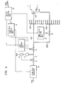
- the two-stage combustion type gas turbine combustor 1 comprises a primary combustion zone 101 and a secondary combustion zone 102 positioned downstream of the primary combustion zone 101.
- the combustor 1 is provided with a primary fuel nozzle 103 for injecting a fuel of gas into the primary combustion zone 101 and a secondary fuel nozzle 104 for injecting a fuel of gas into the secondary combustion zone 102.
- Compressed air necessary for combustion of the fuel is fed to the primary and secondary combustion zones 101, 102 through holes (not shown) made in a casing 105 defining the combustion zones 101, 102.
- the primary and secondary fuel nozzles 103, 104 are fluidly connected to a fuel line 2 through a primary fuel line 201 with a manifold 202 and a secondary fuel line 203 with a manifold 204, respectively.
- the primary and secondary fuel lines 201, 203 are branched from the fuel line 1 downstream of a fuel control valve 4.
- the primary and secondary manifolds 202, 204 each have branch lines, respectively.
- the number of the branch lines of the manifolds 202, 204 corresponds to the number of combustors 1, namely, an example of a gas turbine is provided with about 10 combustors each of which is connected to the branch lines of each of the manifolds 202, 204.
- the fuel line 2 is provided with a pressure-regulating valve 3 and the fuel control valve 4.
- the pressure-regulating valve 3 regulates the pressure of the fuel in the fuel line 2 to a predetermined pressure by means 6 for controlling the pressure-regulating valve 3.
- the pressure-regulating valve control means 6 controls the pressure regulating valve 3 in such a manner that the pressure of the fuel in the fuel line 2 downstream of the pressure-regulating valve 3, which is detected by a pressure sensor 5, is received as a signal related to the detected pressure, the detected pressure is compared with the reference pressure to generate a signal related to the pressure difference between the detected pressure and the reference pressure, and the pressure regulating valve 3 is controlled according to the signal so that the pressure difference will be zero. By controlling thus, the predetermined regulated pressure is obtained.
- the regulated predetermined pressure also can be attained by a conventional pressure regulator.
- the fuel control valve 4 controls the flow rate of fuel in the fuel line 2, according to a load command signal from a load control unit 7 so as to attain a required turbine load during the ordinary turbine operation.
- the flow rate of the fuel passing through the fuel control valve 4 is indirectly expressed by using the following data as parameters:
- the values of P l , P 2 , T 1 and S are detected by the pressure sensor 5 upperstream of the fuel control valve 4, a pressure sensor 11 downstream of the fuel control valve 4, a temperature sensor 10 and a stroke detector 9 of the fuel control valve 4 which detects the stroke related to the opening of the valve 4, respectively.
- the flow rate of the fuel flowing through the fuel control valve 4 is calculated at all times by a flow rate arithmetic unit 8 to generate and deliver a signal related to the resultant flow rate to a flow rate control unit 12.
- the flow rate control unit 12 is constructed so as to control the fuel control valve 4 when a switching instruction is given so that the flow rate.at the time when the instruction is given is taken as a reference, successively detected flow rate is compared with the reference, and the resultant pressure difference is made zero through the actuation of the fuel control valve 4.
- the switching instruction is given by a switch control unit 13.
- the switch control unit 13 receives a load control signal made to run the gas turbine along a load schedule, delivers it to the load control unit 7 during the ordinary operation, and generates switching instructions when the turbine reaches to a predetermined value, for example, 30% of the full turbine load.
- One of the switching instructions is given to the flow rate control unit 12 prior to the load signal to operate the flow rate control unit 12 in the above-mentioned manner, and the other is given to a switching valve 15 to open it through a fuel ratio setting unit 14.
- the switch control unit 13 instructs the switching valve 15 to be opened and switches the control system so that the fuel control valve 4 may be controlled in response to the signal from the flow rate control unit 12 prior to the load control signal.
- the control unit 13 After a predetermined time period has elapsed, moreover, the control unit 13 returns the fuel control valve 4 to be under the control by the load control signal.
- the fuel ratio setting unit 14 is for setting
- Such an opening of the switching valve 15 that a ratio between a flow rate of the fuel flowing in the primary fuel line 201 and a flow rate of the fuel flowing in the secondary fuel line 202 becomes a predetermined value.
- An example of the fuel ratio setting unit is means for limitting an opening of the switching valve 15.
- the secondary fuel nozzle 104 is so made that its total flow resistance is smaller than that of the primary fuel nozzle 103, so that the opening of the switching valve 15 can determine the fuel ratio. Therefore, a signal from the fuel ratio setting unit 14 becomes a fuel ratio signal.
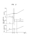
- the gas turbine is controlled by the load control unit 7 receiving a load signal to run along a load schedule as shown in Fig. 2 until the instant to, that is, the time that the gas turbine reaches to a predetermined load, for example, 30% of the full load of the turbine.
- a predetermined load for example, 30% of the full load of the turbine.
- the fuel switching command is generated by the switch control unit 13 having received the load signal related to the predetermined load.
- the flow rate of fuel passing through the fuel control valve 4 is computed as aforementioned by the flow rate arithmetic unit 8 in accordance with the signals indicating the inlet pressure P 1 , the inlet temperature T 1 and the outlet pressure P 2 of the fuel control valve 4, and the stroke S of the fuel control valve 4 at the instant to, and is instructed as the opening control signal of the flow rate control unit 12 to the fuel control valve 4 so that the flow rate may be controlled to a constant level for a fuel line switching period to to t 3 , for example, 1 min..
- the switching valve 15 is instantly opened in accordance with the fuel ratio signal from the fuel ratio setting unit 14 and is completely shifted to have a predetermined opening at the instant t 2 .
- the flow rate of the fuel F 2 is fed to the secondary combustion zone 102 through the secondary fuel nozzles 104 by opening the switching valve'15, in a period of time t l to t 2 , for example, from 0 to about 65% of the total flow rate of the fuel fed to the combustor 1.
- the fuel F 2 reduces the flow rate of the fuel F 1 fed to the primary combustion zone 101 through the primary fuel nozzle 103, for example 100 to about 35% of the total flow rate for the same period of time t i to t 2 .
- the total flow rate of the fuel to the combustor 1 is kept constant Q o for the fuel line switching operation period to to t 3 including a stabilization period t 2 to t 3 . After this switching operation including the stability period, the control is switched to the load control at the instant t 3 to increase the load according to the load schedule.
- the flow rate of the gas through the fuel control valve 4 is metered and is controlled to take the constant value Q o . Therefore, the system can be made highly responsive if the sensors are highly responsive. As a result, even if the switching valve 15 is abruptly opened to drop the pressure P 2 , the opening of the fuel control valve 4 can be instantly dropped to minimize the fluctuations of the flow rate.
- the fluctuations of the total fuel flow rate can be suppressed to about one tenth as large as that of the prior art, as depicted by broken lines in Fig. 2.
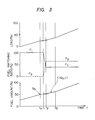
- the total fuel flow rate is held constant for the fuel system switching time period to to t 3 , but the target value can be set to change as a function of the time for the switching period, as shown in Fig. 3.
- the target value be given as a function of both the flow rate Q o at the beginning of the switching operation and the lapse time t from the start of the. switching operation, and that the flow rates metered at the individual instants be controlled to conform to the target values.
- the characteristics for the switching operation are depicted in Fig. 3. In this case, that control can be easily realized by giving the target values, which are to be imposed upon the flow rate control unit 12, as the function of time.
- Fig. 4 shows another embodiment in which the fuel flow rate is metered directly by means of a flow meter detector 19. This embodiment can enjoy a merit that the actual flow rate can be directly determined.
- the other construction is the same as one shown in Fig. 1.
- the fluctuations of the total gas flow rate of the two-stage combustion type fuel line as a result of the switching operation of the fuel gas nozzles can be suppressed to suppress the load fluctuations and the consumption of the lifetimes of the hot parts as much as possible.
Landscapes
- Engineering & Computer Science (AREA)
- Chemical & Material Sciences (AREA)
- Combustion & Propulsion (AREA)
- Mechanical Engineering (AREA)
- General Engineering & Computer Science (AREA)
- Feeding And Controlling Fuel (AREA)
- Engine Equipment That Uses Special Cycles (AREA)
Applications Claiming Priority (2)
| Application Number | Priority Date | Filing Date | Title |
|---|---|---|---|
| JP80186/85 | 1985-04-17 | ||
| JP60080186A JPS61241425A (ja) | 1985-04-17 | 1985-04-17 | ガスタ−ビンの燃料ガス制御方法及び制御装置 |
Publications (2)
| Publication Number | Publication Date |
|---|---|
| EP0198502A1 true EP0198502A1 (fr) | 1986-10-22 |
| EP0198502B1 EP0198502B1 (fr) | 1988-07-20 |
Family
ID=13711336
Family Applications (1)
| Application Number | Title | Priority Date | Filing Date |
|---|---|---|---|
| EP86105343A Expired EP0198502B1 (fr) | 1985-04-17 | 1986-04-17 | Méthode et dispositif de contrôle pour turbine à carburant ou à gaz |
Country Status (3)
| Country | Link |
|---|---|
| US (1) | US4716719A (fr) |
| EP (1) | EP0198502B1 (fr) |
| JP (1) | JPS61241425A (fr) |
Cited By (13)
| Publication number | Priority date | Publication date | Assignee | Title |
|---|---|---|---|---|
| US4890453A (en) * | 1987-02-06 | 1990-01-02 | Hitachi, Ltd. | Method and apparatus for burning gaseous fuel, wherein fuel composition varies |
| GB2206159B (en) * | 1987-06-25 | 1992-02-19 | Gen Electric | A gas turbine engine having a dual manifold fuel system. |
| US5311742A (en) * | 1991-11-29 | 1994-05-17 | Kabushiki Kaisha Toshiba | Gas turbine combustor with nozzle pressure ratio control |
| WO1996000346A1 (fr) * | 1994-06-24 | 1996-01-04 | Armen Borisovich Mkrtchyan | Procede de regulation de la puissance d'un moteur dote d'une partie d'alimentation thermique et d'expansion dynamique interne et moteur base sur ce procede |
| RU2162953C2 (ru) * | 1997-03-12 | 2001-02-10 | Акционерное общество открытого типа Самарский научно-технический комплекс им. Н.Д. Кузнецова | Способ регулирования подачи топлива в газотурбинный двигатель |
| EP1300566A2 (fr) | 2001-10-03 | 2003-04-09 | Mitsubishi Heavy Industries, Ltd. | Dispositif et méthode de régulation pour le taux de distribution de carburant dans des chambres de combustion de turbines à gaz |
| DE112006001317B4 (de) * | 2005-06-06 | 2010-12-09 | Mitsubishi Heavy Industries, Ltd. | Gasturbinen-Brennkammer |
| CN102619625A (zh) * | 2011-01-27 | 2012-08-01 | 通用电气公司 | 用于控制燃气轮机发动机的燃料供应的系统 |
| WO2013127994A3 (fr) * | 2012-03-01 | 2014-02-27 | Nuovo Pignone S.R.L. | Procédé et système de surveillance en temps réel d'une combustion à faible émission d'oxydes d'azote à sec (dln) et par diffusion |
| US9500136B2 (en) | 2015-01-06 | 2016-11-22 | General Electric Company | Systems and methods for generating variable ramp rates for turbomachinery |
| EP2650491A3 (fr) * | 2012-04-11 | 2017-10-25 | General Electric Company | Système et procédé pour détecter des fuites de carburant dans des moteurs à turbine à gaz |
| EP3456946A1 (fr) * | 2017-09-18 | 2019-03-20 | Siemens Aktiengesellschaft | Organe de commande et procédé |
| CN111108278A (zh) * | 2017-09-18 | 2020-05-05 | 西门子股份公司 | 控制器和方法 |
Families Citing this family (60)
| Publication number | Priority date | Publication date | Assignee | Title |
|---|---|---|---|---|
| US5036657A (en) * | 1987-06-25 | 1991-08-06 | General Electric Company | Dual manifold fuel system |
| JPS6419126A (en) * | 1987-07-13 | 1989-01-23 | Hitachi Ltd | Gas turbine fuel controller |
| US5152146A (en) * | 1989-04-06 | 1992-10-06 | Rolls-Royce Plc | Fuel control valve for an aircraft gas turbine engine fuel system |
| US4998202A (en) | 1989-05-19 | 1991-03-05 | United Technologies Corporation | Helicopter, high rotor load speed enhancement |
| US5199265A (en) * | 1991-04-03 | 1993-04-06 | General Electric Company | Two stage (premixed/diffusion) gas only secondary fuel nozzle |
| US5259184A (en) * | 1992-03-30 | 1993-11-09 | General Electric Company | Dry low NOx single stage dual mode combustor construction for a gas turbine |
| US5303542A (en) * | 1992-11-16 | 1994-04-19 | General Electric Company | Fuel supply control method for a gas turbine engine |
| US5289685A (en) * | 1992-11-16 | 1994-03-01 | General Electric Company | Fuel supply system for a gas turbine engine |
| US5402634A (en) * | 1993-10-22 | 1995-04-04 | United Technologies Corporation | Fuel supply system for a staged combustor |
| US5465570A (en) * | 1993-12-22 | 1995-11-14 | United Technologies Corporation | Fuel control system for a staged combustor |
| US6092362A (en) * | 1996-11-27 | 2000-07-25 | Hitachi, Ltd. | Gas-turbine combustor with load-responsive premix burners |
| US6079198A (en) * | 1998-04-29 | 2000-06-27 | General Electric Co. | Pressure compensated fuel delivery system for the combustors of turbomachinery |
| EP1199453A3 (fr) * | 1998-05-08 | 2003-01-22 | Mitsubishi Heavy Industries, Ltd. | Système de lavage des injecteurs de carburant d'une turbine à gaz |
| WO2000012940A1 (fr) * | 1998-08-31 | 2000-03-09 | Siemens Aktiengesellschaft | Procede d'exploitation d'une turbine a gaz et turbine a gaz correspondante |
| WO2000014451A1 (fr) | 1998-09-10 | 2000-03-16 | Siemens Aktiengesellschaft | Procede pour faire fonctionner un bruleur, et ensemble bruleur correspondant |
| JP2000248964A (ja) * | 1999-02-26 | 2000-09-12 | Honda Motor Co Ltd | ガスタービンエンジン |
| US6385960B1 (en) * | 1999-10-14 | 2002-05-14 | General Electric Company | Methods and apparatus for operation of gas turbines |
| US6393823B1 (en) * | 1999-11-05 | 2002-05-28 | General Electric Company | Methods for fuel nozzle staging for gas turbine engines |
| US6622489B1 (en) * | 2000-10-25 | 2003-09-23 | Hybrid Power Generation Systems, Llc | Integrated gas booster modulation control method |
| WO2002036952A2 (fr) * | 2000-10-31 | 2002-05-10 | Honeywell International Inc. | Procede de regulation d'un plan de gestion du debit de carburant destine a une commande de moteur a turbine |
| SE521293C2 (sv) * | 2001-02-06 | 2003-10-21 | Volvo Aero Corp | Förfarande och anordning för tillförsel av bränsle till en brännkammare |
| DE50213936D1 (de) * | 2001-06-22 | 2009-12-03 | Alstom Technology Ltd | Verfahren zum Hochfahren einer Gasturbinenanlage |
| JP3881871B2 (ja) | 2001-11-13 | 2007-02-14 | 三菱重工業株式会社 | ガスタービンの燃料制御方法、及びそれに供する制御装置 |
| JP3978086B2 (ja) * | 2002-05-31 | 2007-09-19 | 三菱重工業株式会社 | 航空機用ガスタービンシステム,及びガスタービンシステム並びにその動作方法 |
| JP3975232B2 (ja) | 2002-10-22 | 2007-09-12 | 川崎重工業株式会社 | ガスタービンエンジンの制御方法および制御システム |
| US7107773B2 (en) * | 2003-09-04 | 2006-09-19 | Siemens Power Generation, Inc. | Turbine engine sequenced combustion |
| GB0323255D0 (en) * | 2003-10-04 | 2003-11-05 | Rolls Royce Plc | Method and system for controlling fuel supply in a combustion turbine engine |
| JP4015656B2 (ja) * | 2004-11-17 | 2007-11-28 | 三菱重工業株式会社 | ガスタービン燃焼器 |
| GB0515034D0 (en) * | 2005-07-21 | 2005-08-31 | Rolls Royce Plc | Method and system for operating a multi-stage combustor |
| JP4119908B2 (ja) * | 2005-09-14 | 2008-07-16 | 三菱重工業株式会社 | ガスタービンの燃焼制御装置 |
| US7752833B2 (en) * | 2006-01-10 | 2010-07-13 | General Electric Company | Methods and apparatus for gas turbine fuel control |
| US7549293B2 (en) * | 2006-02-15 | 2009-06-23 | General Electric Company | Pressure control method to reduce gas turbine fuel supply pressure requirements |
| US7644574B2 (en) * | 2006-08-15 | 2010-01-12 | General Electric Company | Methods and systems for gas turbine engine control |
| JP4831836B2 (ja) * | 2007-12-13 | 2011-12-07 | 三菱重工業株式会社 | ガスタービンの制御方法およびガスタービン発電装置 |
| JP4979615B2 (ja) * | 2008-03-05 | 2012-07-18 | 株式会社日立製作所 | 燃焼器及び燃焼器の燃料供給方法 |
| JP5185757B2 (ja) | 2008-10-01 | 2013-04-17 | 三菱重工業株式会社 | ガスタービンの燃料制御方法および燃料制御装置ならびにガスタービン |
| JP5185791B2 (ja) * | 2008-11-28 | 2013-04-17 | 三菱重工業株式会社 | ガスタービン制御装置 |
| DE102009010611A1 (de) * | 2009-02-25 | 2010-08-26 | Siemens Aktiengesellschaft | Vorrichtung und Verfahren zur Steuerung einer mit mehreren Brennern ausgestatteten Turbine für flüssige oder gasförmige Brennstoffe |
| US20100326081A1 (en) * | 2009-06-29 | 2010-12-30 | General Electric Company | Method for mitigating a fuel system transient |
| IT1396515B1 (it) | 2009-11-27 | 2012-12-14 | Nuovo Pignone Spa | Soglia basata su temperatura di scarico per metodo di controllo e turbina |
| IT1396516B1 (it) * | 2009-11-27 | 2012-12-14 | Nuovo Pignone Spa | Metodo di controllo di modo basato su temperatura di scarico per turbina a gas e turbina a gas |
| EP2458180A1 (fr) * | 2010-11-30 | 2012-05-30 | Siemens Aktiengesellschaft | Procédé de fonctionnement d'une turbine à gaz lors de la régulation de la charge, dispositif de réglage du fonctionnement d'une turbine à gaz et centrale |
| US20120180873A1 (en) * | 2011-01-14 | 2012-07-19 | General Electric Company | Method for replicating a pressure control valve with adjustable response characteristic |
| US8646278B2 (en) * | 2011-02-08 | 2014-02-11 | General Electric Company | Condition measurement apparatus and method |
| EP2597372A2 (fr) | 2011-11-23 | 2013-05-29 | Alstom Technology Ltd | Procédé de fonctionnement d'un dispositif de combustion durant le fonctionnement transitoire |
| US9303562B2 (en) * | 2013-01-15 | 2016-04-05 | General Electric Company | Methods and systems for operating gas turbine engines |
| CN104075344B (zh) * | 2013-03-25 | 2016-07-06 | 通用电气公司 | 用低热值燃料启动和运作燃气轮机的燃料喷嘴系统和方法 |
| BR112016003574B1 (pt) * | 2013-08-20 | 2021-10-13 | Snecma | Sistema de injeção de combustível, método de injeção de combustível, produto de programa de computador e mídia de armazenamento |
| EP2853719A1 (fr) * | 2013-09-25 | 2015-04-01 | Alstom Technology Ltd | Turbine à gaz avec injection de carburant étagée |
| EP2857658A1 (fr) * | 2013-10-01 | 2015-04-08 | Alstom Technology Ltd | Turbine à gaz avec agencement de combustion séquentielle |
| US20150107255A1 (en) * | 2013-10-18 | 2015-04-23 | General Electric Company | Turbomachine combustor having an externally fueled late lean injection (lli) system |
| US20150337739A1 (en) * | 2014-05-20 | 2015-11-26 | Wellhead Electric Company, Inc. | Ramp rate control for a gas turbine |
| US10451509B2 (en) * | 2014-06-04 | 2019-10-22 | United Technologies Corporation | Method for determining a fault within a flow divider |
| US10317082B2 (en) * | 2014-08-12 | 2019-06-11 | Hamilton Sundstrand Corporation | Distributed fuel control system |
| EP3822468B1 (fr) * | 2019-11-18 | 2024-04-03 | Ansaldo Energia Switzerland AG | Turbine à gaz pouvant fonctionner à très faible charge partielle et procédé de commande d'une turbine à gaz |
| JP7307701B2 (ja) * | 2020-05-01 | 2023-07-12 | 三菱重工業株式会社 | ガスタービン燃焼器 |
| US11346281B2 (en) * | 2020-08-21 | 2022-05-31 | Woodward, Inc. | Dual schedule flow divider valve, system, and method for use therein |
| US11821366B2 (en) * | 2021-06-17 | 2023-11-21 | General Electric Company | Methods of control for management of hot fuel |
| US11668241B2 (en) | 2021-06-17 | 2023-06-06 | General Electric Company | Methods of control for management of hot fuel |
| US11746711B2 (en) * | 2021-08-12 | 2023-09-05 | Pratt & Whitney Canada Corp. | Pulse width modulation drive for staged fuel manifolds |
Citations (2)
| Publication number | Priority date | Publication date | Assignee | Title |
|---|---|---|---|---|
| US3078046A (en) * | 1960-01-01 | 1963-02-19 | Dowty Fuel Syst Ltd | Liquid supply systems |
| US4470257A (en) * | 1982-04-30 | 1984-09-11 | Westinghouse Electric Corp. | Isochronous and droop speed control for a combustion turbine |
Family Cites Families (8)
| Publication number | Priority date | Publication date | Assignee | Title |
|---|---|---|---|---|
| US3552123A (en) * | 1969-06-26 | 1971-01-05 | United Aircraft Corp | Sequential fuel control |
| US3925002A (en) * | 1974-11-11 | 1975-12-09 | Gen Motors Corp | Air preheating combustion apparatus |
| US4498288A (en) * | 1978-10-13 | 1985-02-12 | General Electric Company | Fuel injection staged sectoral combustor for burning low-BTU fuel gas |
| US4420929A (en) * | 1979-01-12 | 1983-12-20 | General Electric Company | Dual stage-dual mode low emission gas turbine combustion system |
| US4291532A (en) * | 1979-03-23 | 1981-09-29 | Dowty Fuel Systems Limited | Fuel supply system |
| US4292801A (en) * | 1979-07-11 | 1981-10-06 | General Electric Company | Dual stage-dual mode low nox combustor |
| JPS59129330A (ja) * | 1983-01-17 | 1984-07-25 | Hitachi Ltd | 予混合燃焼形ガスタ−ビン |
| JPS6057131A (ja) * | 1983-09-08 | 1985-04-02 | Hitachi Ltd | ガスタ−ビン燃焼器の燃料供給方法 |
-
1985
- 1985-04-17 JP JP60080186A patent/JPS61241425A/ja active Granted
-
1986
- 1986-04-16 US US06/852,820 patent/US4716719A/en not_active Expired - Fee Related
- 1986-04-17 EP EP86105343A patent/EP0198502B1/fr not_active Expired
Patent Citations (2)
| Publication number | Priority date | Publication date | Assignee | Title |
|---|---|---|---|---|
| US3078046A (en) * | 1960-01-01 | 1963-02-19 | Dowty Fuel Syst Ltd | Liquid supply systems |
| US4470257A (en) * | 1982-04-30 | 1984-09-11 | Westinghouse Electric Corp. | Isochronous and droop speed control for a combustion turbine |
Non-Patent Citations (1)
| Title |
|---|
| TRANSACTIONS OF THE ASME, JOURNAL OF ENGINEERING FOR GAS TURBINES AND POWER, vol. 106, October 1984, pages 795-800, New York, US; K. AOYAMA et al.: "Development of a dry low NOx combustor for a 120-MW gas turbine" * |
Cited By (21)
| Publication number | Priority date | Publication date | Assignee | Title |
|---|---|---|---|---|
| US4890453A (en) * | 1987-02-06 | 1990-01-02 | Hitachi, Ltd. | Method and apparatus for burning gaseous fuel, wherein fuel composition varies |
| GB2206159B (en) * | 1987-06-25 | 1992-02-19 | Gen Electric | A gas turbine engine having a dual manifold fuel system. |
| US5311742A (en) * | 1991-11-29 | 1994-05-17 | Kabushiki Kaisha Toshiba | Gas turbine combustor with nozzle pressure ratio control |
| WO1996000346A1 (fr) * | 1994-06-24 | 1996-01-04 | Armen Borisovich Mkrtchyan | Procede de regulation de la puissance d'un moteur dote d'une partie d'alimentation thermique et d'expansion dynamique interne et moteur base sur ce procede |
| RU2162953C2 (ru) * | 1997-03-12 | 2001-02-10 | Акционерное общество открытого типа Самарский научно-технический комплекс им. Н.Д. Кузнецова | Способ регулирования подачи топлива в газотурбинный двигатель |
| EP1300566A2 (fr) | 2001-10-03 | 2003-04-09 | Mitsubishi Heavy Industries, Ltd. | Dispositif et méthode de régulation pour le taux de distribution de carburant dans des chambres de combustion de turbines à gaz |
| EP1300566A3 (fr) * | 2001-10-03 | 2009-11-04 | Mitsubishi Heavy Industries, Ltd. | Dispositif et méthode de régulation pour le taux de distribution de carburant dans des chambres de combustion de turbines à gaz |
| US8671690B2 (en) | 2005-06-06 | 2014-03-18 | Mitsubishi Heavy Industries, Ltd. | Combustor of gas turbine |
| DE112006001317B4 (de) * | 2005-06-06 | 2010-12-09 | Mitsubishi Heavy Industries, Ltd. | Gasturbinen-Brennkammer |
| CN102619625A (zh) * | 2011-01-27 | 2012-08-01 | 通用电气公司 | 用于控制燃气轮机发动机的燃料供应的系统 |
| US9921577B2 (en) | 2012-03-01 | 2018-03-20 | Nuovo Pignone Srl | Method and system for diagnostic rules for heavy duty gas turbines |
| US9274520B2 (en) | 2012-03-01 | 2016-03-01 | Nuovo Pignone Srl | Method and system for condition monitoring of a group of plants |
| WO2013127994A3 (fr) * | 2012-03-01 | 2014-02-27 | Nuovo Pignone S.R.L. | Procédé et système de surveillance en temps réel d'une combustion à faible émission d'oxydes d'azote à sec (dln) et par diffusion |
| US10088839B2 (en) | 2012-03-01 | 2018-10-02 | Nuovo Pignone Srl | Method and system for real-time performance degradation advisory for centrifugal compressors |
| EP2650491A3 (fr) * | 2012-04-11 | 2017-10-25 | General Electric Company | Système et procédé pour détecter des fuites de carburant dans des moteurs à turbine à gaz |
| US9500136B2 (en) | 2015-01-06 | 2016-11-22 | General Electric Company | Systems and methods for generating variable ramp rates for turbomachinery |
| EP3456946A1 (fr) * | 2017-09-18 | 2019-03-20 | Siemens Aktiengesellschaft | Organe de commande et procédé |
| WO2019053063A1 (fr) * | 2017-09-18 | 2019-03-21 | Siemens Aktiengesellschaft | Dispositif de commande et procédé |
| CN111108278A (zh) * | 2017-09-18 | 2020-05-05 | 西门子股份公司 | 控制器和方法 |
| RU2749287C1 (ru) * | 2017-09-18 | 2021-06-08 | Сименс Акциенгезелльшафт | Способ управления газовой турбиной и считываемый компьютером носитель хранения для выполнения такого способа |
| US11815032B2 (en) | 2017-09-18 | 2023-11-14 | Siemens Energy Global GmbH & Co. KG | Controller and method |
Also Published As
| Publication number | Publication date |
|---|---|
| EP0198502B1 (fr) | 1988-07-20 |
| JPH0574697B2 (fr) | 1993-10-19 |
| JPS61241425A (ja) | 1986-10-27 |
| US4716719A (en) | 1988-01-05 |
Similar Documents
| Publication | Publication Date | Title |
|---|---|---|
| EP0198502B1 (fr) | Méthode et dispositif de contrôle pour turbine à carburant ou à gaz | |
| US7966802B2 (en) | Methods and apparatus for operating gas turbine engine systems | |
| EP0672220B1 (fr) | Ensemble vanne de repartition de combustible pour turbine a gaz | |
| EP2112572B1 (fr) | Procédé et système de fonctionnement de systèmes de moteur de turbine à gaz | |
| CN103362654B (zh) | 自动调整燃气轮机燃烧的操作的方法 | |
| US5584171A (en) | Gas turbine control method and apparatus | |
| US7003939B1 (en) | Method for the adaption of the operation of a staged combustion chamber for gas turbines | |
| JP2585324B2 (ja) | ガスタービンの制御方法及びその装置 | |
| EP0501313A1 (fr) | Installation de combustion et procédé pour sa régulation | |
| US6986245B2 (en) | Fuel supply system and an associated operating method | |
| JPH063148B2 (ja) | 二重気体燃料焚ガスタ−ビンの燃料制御装置 | |
| JPH0544537B2 (fr) | ||
| EP2577025B1 (fr) | Procédé pour accroître une capacité de charge conforme aux normes d'émissions pour un système à cycle combiné | |
| JPH11159756A (ja) | 油焚dln燃焼器の水噴射制御装置 | |
| JPH0996227A (ja) | ガス化プラントの圧力制御装置 | |
| JP2004027891A (ja) | 燃料弁開度制御システム | |
| JPS62255538A (ja) | ガスタ−ビン制御装置 | |
| JPH0412329Y2 (fr) | ||
| JP2001012257A (ja) | ガスタービン燃焼器の燃料・蒸気供給装置 | |
| JP3131804B2 (ja) | ガスタービン用燃焼器における燃料分配制御装置 | |
| JPH07166891A (ja) | ガスタービン制御装置 | |
| JP3473880B2 (ja) | 交番燃焼システムにおける空気流量の調節構造 | |
| JPH0412330Y2 (fr) | ||
| JPS61138836A (ja) | ガスタ−ビン制御装置 | |
| KR20250121116A (ko) | 가스 터빈 제어 장치, 가스 터빈 제어 방법, 및, 가스 터빈 제어 프로그램을 기록한 컴퓨터에서 독취 가능한 기록 매체 |
Legal Events
| Date | Code | Title | Description |
|---|---|---|---|
| PUAI | Public reference made under article 153(3) epc to a published international application that has entered the european phase |
Free format text: ORIGINAL CODE: 0009012 |
|
| AK | Designated contracting states |
Kind code of ref document: A1 Designated state(s): FR GB |
|
| 17P | Request for examination filed |
Effective date: 19861029 |
|
| 17Q | First examination report despatched |
Effective date: 19871002 |
|
| GRAA | (expected) grant |
Free format text: ORIGINAL CODE: 0009210 |
|
| AK | Designated contracting states |
Kind code of ref document: B1 Designated state(s): FR GB |
|
| ET | Fr: translation filed | ||
| PLBE | No opposition filed within time limit |
Free format text: ORIGINAL CODE: 0009261 |
|
| STAA | Information on the status of an ep patent application or granted ep patent |
Free format text: STATUS: NO OPPOSITION FILED WITHIN TIME LIMIT |
|
| 26N | No opposition filed | ||
| PGFP | Annual fee paid to national office [announced via postgrant information from national office to epo] |
Ref country code: FR Payment date: 19980320 Year of fee payment: 13 |
|
| PGFP | Annual fee paid to national office [announced via postgrant information from national office to epo] |
Ref country code: GB Payment date: 19980414 Year of fee payment: 13 |
|
| PG25 | Lapsed in a contracting state [announced via postgrant information from national office to epo] |
Ref country code: GB Free format text: LAPSE BECAUSE OF NON-PAYMENT OF DUE FEES Effective date: 19990417 |
|
| GBPC | Gb: european patent ceased through non-payment of renewal fee |
Effective date: 19990417 |
|
| PG25 | Lapsed in a contracting state [announced via postgrant information from national office to epo] |
Ref country code: FR Free format text: LAPSE BECAUSE OF NON-PAYMENT OF DUE FEES Effective date: 19991231 |
|
| REG | Reference to a national code |
Ref country code: FR Ref legal event code: ST |